a455231826378487a48cc8aff0534244.ppt
- Количество слайдов: 43


 Grzegorz Grzelak Li. CAS Linear Collider")
Zróbmy to prosto (czyli jak ustawić akcelerator liniowy) Grzegorz Grzelak Li. CAS Linear Collider Alignment & Survey Seminarium Fizyki Wielkich Energii; Warszawa; 14 X 2005

Linear Collider Challenge • • • Detector vs. “machine” Accelerator: the real challenge Beam energy (high electric field gradient) Luminosity (colliding nano-meter size beams) e+/e- high intensity sources Polarisation Beam diagnostic (laser wires, BPM, …) Beam-based feedback to IP Accelerator alignment and stabilisation: • -- main liniac • -- beam delivery and final focus (final doublet)

Outline • • • Motivation for Linear Collider Importance of Accelerator Alignment Proposed Solution: New Instrument Technology used: FSI and LSM Performance Simulations Summary/Plans
, but")
Current LC R&D Efforts The ILC will be based on SCRF (TESLA Technology), but will be designed by a global collaboration. Much of the layout & parameters will be re-evaluated in light of what has been learnt over the last few years (US-Options study (NLC), JLC, …) R&D on the two-beam CLIC concept continues as possible future path to multi-Te. V

Colliders Energy Frontier ILC LEP 2 at CERN Ecm = 200 Ge. V PRF = 30 MW

Why build linear collider ? Synchrotron Radiation: – For ~1% Synchrotron radiation loss LEP II Super-LEP Energy 200 Ge. V 500 Ge. V d. E / Rev 2. 0 Ge. V 5 Ge. V Radius 4. 3 km 168 km Energy loss must be replaced by RF system cost scaling $ Ecm 2

Solution: Linear Collider No Bends, but lots of RF! e+ e~15 -20 km For a Ecm = 1 Te. V machine: Effective gradient G = 500 GV / 15 km ~ 35 MV/m Note: for LC, $tot ~ E However: Perfect Alignment crucial for High Luminosity
 • Beam energy O(500 Ge. V) • Beams start")
Linear Collider (for example Tesla) • Beam energy O(500 Ge. V) • Beams start at O(0. 1 mm) • beams end up O(1 nm) at interaction point • no recirculation, you just have one shot to collide a given bunch
 • Continuously survey tunnel during construction • Frequently survey")
Survey Problem (survey happens often) • Continuously survey tunnel during construction • Frequently survey empty tunnel to determine if it has settled sufficiently to install collider. • Survey collider during installation. • Re-survey parts of collider when alignment problems arise. • Re-survey parts of collider during maintenance, component exchange, other instrument installation. • Survey final focus parts after experiment access
 • Tight space (~1 m")
Survey and Alignment Problem • Long tunnel (~30 km) • Tight space (~1 m wide) • Curved tunnel sections • Significant slopes possible • Some sections follows geoid, others are geometrically straight • Temperature and pressure gradients in tunnel • Electrically noisy environment
 Powerspectrum of ground motion in various HEP")
LCs move… (time scales of ground motion) Powerspectrum of ground motion in various HEP tunnels 70 nm LEP: 60 to 180 mm/year
 • Reference survey (the hard")
The ILC survey and alignment process (in the tunnel) • Reference survey (the hard part): s<200 microns/600 m – establish co-ordinates of regular array of reference markers along entire tunnel wall • Stake out: s<50 microns any point – Relate external accelerator component’s markers to reference markers • Alignment: s<100 microns any point – adjust position of accelerator element to get closer to nominal
 • Fiducialisation: s≥ 300 microns")
The ILC survey and alignment process (outside the tunnel) • Fiducialisation: s≥ 300 microns – Relate external markers to relevant active centre line of accelerator element • Build tolerances: – Internal to an accelerator element s~100 microns • static variation of several active elements around the centre line (scatter of cavities in cryo-module) • dynamic changes of elements with load, current, trim, external temperature, etc.

TTF: cryo-module structure Fiducial marker main beam line
: – 200 mm")
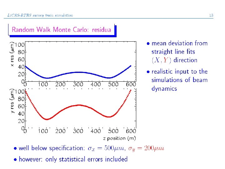
Survey and Alignment: novel solutions needed • TESLA Specification (reference survey): – 200 mm vertical over 600 meters (=betatron wavelength) • Open air survey too slow and too inaccurate • Need new instrument that matches requirements RTRS (Rapid Tunnel Reference Surveyor) • New technology : FSI – Frequency Scanning Interferometry (interferometric distance measurement) and Laser Straightness Monitors (LSM) • Automated measurement needed

Survey Implementation wall markers internal FSI SM beam external FSI Tunnel Wall This instrument can be integrated with the train collider component Reconstructed tunnel shapes (relative coordinates)

Li. CAS sensing modules Extrenal FSI System measures Wall marker location Internal FSI System Dz. & Dx, Dy & Da, Db between cars tilt meters (not shown) measure Dg (rotation around z) Straightness Monitor Dx, Dy & Da, Db between cars

Li. CAS Measurement Unit • Internal FSI lines operate in vacuum • Scalable TELECOM style infrared lasers • EDFA light amplifiers Internal FSI beams and LSM beam Wall mounted retro-reflector External FSI beams All measurements in mm

Inner Chassis • Inner Chassis provides – 6 -DOF motion for unit alignment – vibration damping – sensing of tunnel bar codes
")
Previous Generation RTRS (DESY)

FSI = Frequency Scannig Interferometry

FSI Principle • Interferometric ABSOLUTE length measurement system • Originally developed at Oxford for online alignment of ATLAS SCT tracker • Measurement precision is 1 mm over 5 m Tunable Laser IRef Reference Interferometer Length = L time Change of phase: DFRef IGLI Grid Line Interferometer (GLI) Length = D time Change of phase: DFGLI
 • GLI’s do the length measurement jewels support structure delivery fibre")
FSI (cont. ) • GLI’s do the length measurement jewels support structure delivery fibre quill return fibre variable path fixed path retrobeam splitter reflector

FSI System Amplitude Modulation @ f 1 f 2 Laser 1 C-Band Amplifier (1520 -1570) Laser 2 L-Band Amplifier (1572 -1630) Amplitude Modulation @ f 2 Splitter Tree detector piezo Reference Interferometer Detectors @ f 1 , F 1 Demodulator @ f 2 , F 1 Amplifier ADC 2 MHz Amplifier ADC 2 MHZ Amplifier ADC 20 MHZ Quill Buffer Memory Demodulator Retro Reflector GLI USB-2 Readout Board

LSM = Laser Straightness Monitor

LSM Principle • • Light beam define the reference straight line Used to measure carriage transverse translations and rotations Low coherence length diode laser to avoid interference on CCD Aprox. 1 micron precision over length of train y z Translation: Spots move same direction Rotation: Spots move opposite directions CCD Camera

LSM: LAB tests Camera looking at low -coherence laser Fitted Gaussian to camera image

Laser enclosure Straightness Monitoring Li. CAS Lab @Oxford Vibration isolated optical table for FSI reference interferometers FSI rack Long FSI test stages Motion control rack USB-2 DAQ development 5 x 1. 5 m 2 table

used for internal LSM calibration

New FSI Work • Short 6 -line FSI system for 3 D wall marker reconstruction. Splitter Tree Amplifier Laser Retro Reflector 3 D-Piezo Stage

Simulation Software • Simulgeo: simulation and reconstruction software for optogeometrical systems. • (L. Brunel, CMS note 1998/079) • Many features: – – – Laser beams CCD cameras Mirrors Distancemeters. . . • Description of mechanical support by grouping various objects into local frames
 • Build opto-geometric model")
Reference Survey Simulations (FULL SIMULATION: short distance < 100 m) • Build opto-geometric model of all measurements in a 6 -car train and all reference wall markers using SIMULGEO • Add up to 20 trains in advancing locations into the model è model consists of 20 trains measuring 26 wall markers. è total of O(10. 000) elements and measurements with individual errors • Most wall markers get measured 6 times in overlapping measurements this is how trains correlate with each other • Perform error propagation: – from: position errors of elements in the cars and measurement errors – to : errors of wall markers, – i. e. invert error matrix of rank N 2 = 10. 0002 • Limit of this procedure is memory of computer 20 trains need close to 1 GByte and 34 h on 2 GHz CPU

Laser beam parallel to Gravity @ car 1 Simulgeo Model of RTRS only first and last car shown Laser beam parallel to Gravity @ car 6 1 st CCD faking clinometer wall marker 1 LSM-CCDs for return beam wall marker 2 internal FSI lines intermediate cars not shown LSM-CCDs for incoming beam 2 nd CCD faking clinometer retro reflector straightness monitor laser beam

Single Train Simulations Measurements and all geometrical objects have random errors in position and angle Only measurements have errors
")
Multi Train Simulations • 15 train-stops Simulgeo simulation reaches max. memory capacity (2 GB) • Use simple train model with errors in measurements only • Hundreds of cross-checks against parameter variations

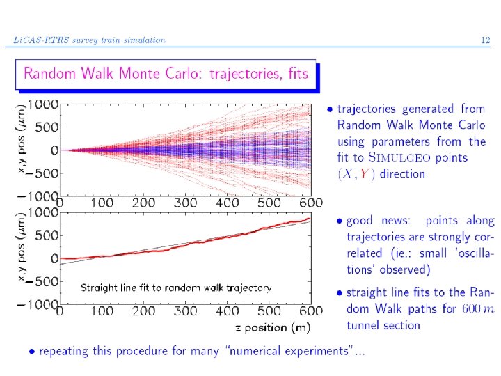
Random Walk Model • Fit MC of random walks against Simulgeo model – obtain s(Da), s(Db), s(Dx), s(Dy) from the fit Analytically compute errors in the n’th step: X Dxi+1 Dai L Dai+1 Z
")
Reference Survey Simulations (long distance >100 m)

Test Tunnel Preparation • 55 m long service tunnel at DESY • tunnel tests showed walls stable enough • air conditioning • installed high speed WLAN and LAN • installing laser interlocks and safety systems • ready for use well before RTRS prototype expected to arrive

Summary and Plans • Li. CAS technology is capable to measure the ILC tunnel to required precision • Work in progress on hardware and software • The 3 -car prototype beginning of 2006 • Get 2 nd generation Li. CAS train into X-FEL tunnel • Stake-Out instrument to measure accelerator components against wall markers • Michelson enhanced FSI (M-FSI) for fast stabilisation of final focus magnets

Volts Recent Developments • Amplitude Modulation on FSI fringe @ 40 & 80 k. Hz (now) 0. 5 & 1 MHz (later) 15% mod. Volts Time • High Pass Filter • FSI fringe stored as amplitude on Carrier (a’la AM radio) • Demodulation reproduces FSI Fringes Time

Recent Developments l 1 t 0 t 1 time Amplitude Modulation @ f 1 Laser 1 f 2 Laser 2 Detector Amplitude Modulation @ f 2 M 1 M 2 Volts wavelength l 2 Demodulator @ f 1 , F 1 l 0 time Demodulator @ f 2 , F 1 Volts wavelength l 2 t 1 time
a455231826378487a48cc8aff0534244.ppt