4627aea791fa2aa6948f78b5159b8f3a.ppt
- Количество слайдов: 186
 Wireless LANs EPL 657 Andreas Pitsillides Contains slides and ideas from Teknillinen Korkeakoulou, Finland: Wireless personal, local, metropolitan, and wide area networks, S-72. 3240, and Ent. Net@Supercom 2004 WLAN tutorial, 23/6/2004 1
 Feature Topic on the Future of Wi-Fi • Wi-Fi is a well researched topic with wide applicability… why study further? • E. g. call for Papers IEEE Communications Magazine – emerging and future generations of IEEE 802. 11 Wi-Fi, such as Wi -Fi CERTIFIED(tm) ac and Wi. Gig CERTIFIED(tm), will be capable of achieving multiple gigabits per second speeds and be used to do everything from simple web browsing and peer-to-peer sharing, to multimedia streaming, real-time teleconferencing, cable replacement, and wireless docking, to name a few. Coupled with the recent introduction of Wi-Fi CERTIFIED(tm) Passpoint by the Wi-Fi Alliance, users can further enjoy seamless and secure connectivity when roaming between cellular and Wi-Fi and between Wi-Fi networks. 2
 Future wi-fi technologies • Topics of interest include, but are not limited to, the following categories: – - Technological overview of the recent, emerging, and future Wi-Fi technologies – - PHY-, MAC-, and network-layer architectures and protocols – - Privacy and Security – - Spectrum and Regulatory – - Wi-Fi and cellular interworking – - Implementation and deployment challenges – - Emerging applications and services 3
 WIRELESS LAN (WLAN) • Selected topics • • • Introduction WLAN aims WLAN characteristics WLAN design goals Infrared vs radio transmission Infrastructure-based vs ad-hoc networks WLAN Standards IEEE 802. 11 WLAN Roaming WLAN Security WLAN enhancements WLAN design issues • Other technologies (separate slides) 4
 Why Wireless LANs (WLANs) • Mobility (portability) and Flexibility • Places where there is no cabling infrastructure / Hard to wire areas • Reduced cost of wireless systems • Improved flexibility of wireless systems • Cost – Relatively low cost of deployment – Continual drop in price for WLAN equipment 5
 Wireless LAN Applications • • LAN Extension Cross building interconnection Nomadic access Ad hoc networks 6
 Vertical Markets n n n n Factory floor Home networking Hospital Office workers Retail stores Warehouse Stock market n n n Airport Hotel Starbuck College campus Convention Center Miscellaneous 7
 Example WLAN deployment - Hotel n Competing Technologies n n n n Wired Ethernet (802. 3) Phone Line x. DSL Power Line Proposed: Wireless LAN (802. 11) Why: Price/Performance and ease of deployment Current status: almost all major hotel chains in major (and not so major) cities 8
 Wireless LANs 9
 Wireless LAN considerations • • • Throughput Number of nodes Connection to backbone Service area Battery power consumption Transmission robustness and security Collocated network operation License free operation Handoff/roaming Dynamic configuration 10
 WLANs goal • A mature market introducing the flexibility of wireless access into office, home, or production environments. • Typically restricted in their diameter to buildings, a campus, single rooms etc. • The global goal of WLANs is to replace office cabling, increase flexibility of connection especially for portable devices and, additionally, to introduce a higher flexibility for ad hoc communication in, e. g. , group meetings. 11
 WLAN characteristics • Advantages: – very flexible within radio coverage – ad-hoc networks without previous planning possible – wireless networks allow for the design of small, independent devices – more robust against disasters (e. g. , earthquakes, fire) 12
 WLAN characteristics • Disadvantages: – typically lower bandwidth compared to wired networks (~11 – 300 Mbit/s) due to limitations in radio transmission, higher error rates due to interference, and higher delay/delay variation due to extensive error correction and error detection mechanisms • offer lower Qo. S – a number of proprietary solutions, especially for higher bit-rates, and standards take their time (e. g. , IEEE 802. 11 n) • standardized functionality plus many enhanced features • additional features only work in a homogeneous environment (i. e. , when adapters from same vendors used) – products have to follow many national restrictions if working wireless, it takes a very long time to establish global solutions 13
 WLAN design goals • global, seamless operation of WLAN products • low power for battery use (special power saving modes and power management functions) • no special permissions or licenses needed (licensefree band) • robust transmission technology • easy to use for everyone, simple management • protection of investment in wired networks (support the same data types and services) • security – no one should be able to read other’s data, privacy – no one should be able to collect user profiles, safety – low radiation 14
 Known problems with WLANs • Wireless link characteristics: media is error prone and the bit error rate (BER) is very high compared to the BER of wired networks. • Carrier Sensing/collision detection is difficult in wireless networks because a station is incapable of listening to its own transmissions in order to detect a collision (more later). • The Hidden Terminal problem also decreases the performance of a WLAN (more later). • Mobility (variation in link reliability, seamless connections required, battery limitations) (more later) 15
 Wireless Link Characteristics Differences from wired link …. – decreased signal strength: radio signal attenuates as it propagates through matter (path loss) – interference from other sources: standardized wireless network frequencies (e. g. , 2. 4 GHz) shared by other devices (e. g. , phone); also devices (e. g. motors) interfere as well (noise) – multipath propagation: radio signal reflects off objects, arriving at destination at slightly different times (channel quality varies over time) – shared with other technologies and spectrum users – more difficult security (shared medium) …. make communication across (even a point to point) wireless link much more “difficult” 16
 Wireless LAN Radio Technology • • Infrared (IR) LANs Spread spectrum LANs Narrow band microwave Laser beam 17
 ISM frequency bands ISM (Industrial, Scientific and Medical) frequency bands: • 900 MHz band (902 … 928 MHz) • 2. 4 GHz band (2. 4 … 2. 4835 GHz) • 5. 8 GHz band (5. 725 … 5. 850 GHz) Anyone is allowed to use radio equipment for transmitting in these bands (provided specific transmission power limits are not exceeded) without obtaining a license. 18
 WLAN Standards • Several WLAN standards, e. g. : – IEEE 802. 11 b offering 11 Mbit/s at 2. 4 GHz – The same radio spectrum is used by Bluetooth • A short-range technology to set-up wireless personal area networks with gross data rates less than 1 Mbit/s – IEEE 802. 11 a, operating at 5 GHz and offering gross data rates of 54 Mbit/s – IEEE 802. 11 g offering up to 54 Mbit/s at 2. 4 GHz. – IEEE 802. 11 n up and coming standard up to 300 Mbit/s (two spatial streams; 600 Mbit/s with 4 spatial streams) –… 19
 WLAN Standards Wireless LAN 2. 4 GHz 5 GHz 802. 11 n (300 Mb/sec) 802. 11 b 802. 11 g Hi. SWANa 802. 11 a Hiper. LAN 2 (2 Mbps) (11 Mbps) (22 -54 Mbps) (54 Mbps) Home. RF 2. 0 Bluetooth Home. RF 1. 0 (10 Mbps) (1 Mbps) (2 Mbps) 802. 11 e 802. 11 f 802. 11 h 802. 11 i (Qo. S) (IAPP) (TPC-DFS) (Security) 802. 11 Protocols under development 20
 IEEE 802 standardisation framework 802. 1 802. 2 Logical Link Control (LLC) Management 802. 3 802. 5 802. 11 Medium Access Control (MAC) MAC CSMA/CA 802. 3 802. 5 802. 11 a 802. 11 b 802. 11 g PHY PHY PHY CSMA/CD (Ethernet) Token Ring CSMA/CA (Wireless LAN) 802. 11 n (300 Mb/sec) Many more protocols recently developed or under development 21
 Recent IEEE 802 standardisation efforts A recent call for papers (CFPs): A new generation of Wireless Local Area Networks (WLANs) is going to make its appearance in the upcoming years, with the IEEE 802. 11 aa (Robust Audio Video Transport Streaming), IEEE 802. 11 ac (Very-high throughput < 6 GHz), IEEE 802. 11 af (TV White Spaces) and IEEE 802. 11 ad (Very-high throughput ~60 GHz), as examples of the most expected ones. Nevertheless, all nextgeneration standards will consider some of the most significant advances on the wireless communication and networking area in the last decade, developed by a highly active community, in both academia and industry. This special issue requests papers that advance the state-of-the-art of the recent and on-going IEEE 802. 11 standards (i. e. , IEEE 802. 11 p, IEEE 802. 11 s, IEEE 802. 11 aa, IEEE 802. 11 ac, IEEE 802. 11 ad, IEEE 802. 11 ae, IEEE 802. 11 ah, IEEE 802. 11 af, IEEE 802. 11 ai, etc. ), as well as present mechanisms and solutions, from MAC or above layers, that could be readily transferred to the not -yet finished standards or their future amendments. 22
 IEEE 802 wireless network technology options Network definition IEEE standard Known as Wireless personal area network (WPAN) IEEE 802. 15. 1 Bluetooth Low-rate WPAN (LRWPAN) IEEE 802. 15. 4 Zig. Bee Wireless local area network (WLAN) IEEE 802. 11 Wi. Fi Wireless metroplitan area network (WMAN) IEEE 802. 16 Wi. MAX 23
 IEEE 802. 11 standard • As the standards number indicates, this standard belongs to the group of 802. x LAN standards. • This means that the standard specifies the physical and medium access layer adapted to the special requirements of wireless LANs, but offers the same interface as the others to higher layers to maintain interoperability. • The primary goal of the standard was the specification of a simple and robust WLAN which offers time-bounded and asynchronous services. 24
 IEEE 802. 11 Wireless LAN • 802. 11 g • 802. 11 b – 2. 4 -5 GHz unlicensed spectrum – up to 11 Mbps – direct sequence spread spectrum (DSSS) in physical layer • all hosts use same chipping code • 802. 11 a – 5 -6 GHz range – up to 54 Mbps • Shading is much more severe compared to 2. 4 GHz • Depending on the SNR, propagation conditions and distance between sender and receiver, data rates may drop fast n n – 2. 4 -5 GHz range – up to 54 Mbps – Benefits from the better propagation characteristics at 2. 4 GHz compared to 5 GHz • Backward compatible to 802. 11 b • 802. 11 n: multiple antennae – 2. 4 -5 GHz range – typically 200++ Mbps • IEEE 802. 11 e – MAC enhancements for providing some Qo. S • Some Qo. S guarantees can be given only via polling using PCF all use CSMA/CA for multiple access all have base-station and ad-hoc network versions 25
 Characteristics of selected wireless link standards Data rate (Mbps) 200 54 5 -11 802. 11 n 802. 11 a, g 802. 11 b 4 1 802. 11 a, g point-to-point data 802. 16 (Wi. MAX) UMTS/WCDMA-HSPDA, CDMA 2000 -1 x. EVDO 3 G cellular enhanced 802. 15 . 384 3 G UMTS/WCDMA, CDMA 2000 . 056 2 G IS-95, CDMA, GSM Indoor Outdoor 10 -30 m 50 -200 m Mid-range outdoor Long-range outdoor 200 m – 4 Km 5 Km – 20 Km 26
 Infrastructure-based vs ad-hoc wireless networks Infrastructurebased wireless networks AP AP wired network AP: Access Point AP • Infrastructure networks provide access to other networks. • Communication typically takes place only between the wireless nodes and the access point, but not directly between the wireless nodes. • The access point does not just control medium access, but also acts as a bridge to other wireless or wired networks. 27
 Infrastructure-based vs ad-hoc wireless networks • Several wireless networks may form one logical wireless network: – The access points together with the fixed network in between can connect several wireless networks to form a larger network beyond actual radio coverage. • Network functionality lies within the access point (controls network flow), whereas the wireless clients can remain quite simple. • Can use different access schemes with or without collision. – Collisions may occur if medium access of the wireless nodes and the access point is not coordinated. • If only the access point controls medium access, no collisions are possible. – Useful for quality of service guarantees (e. g. , minimum bandwidth for certain nodes) – The access point may poll the single wireless nodes to ensure the data rate. 28
 Infrastructure-based vs ad-hoc wireless networks • Infrastructure-based wireless networks loose some of the flexibility wireless networks can offer in general: – They cannot be used for disaster relief in cases where no infrastructure is left. 29
 Infrastructure-based vs ad-hoc wireless networks Ad-hoc wireless networks • No need of any infrastructure to work – greatest possible flexibility • Each node communicate with other nodes, so no access point controlling medium access is necessary. – The complexity of each node is much higher • implement medium access mechanisms and forwarding data 30
 Infrastructure-based vs ad-hoc wireless networks • Nodes within an ad-hoc network can only communicate if they can reach other physically – if they are within each other’s radio range – if other nodes can/want to forward the message • IEEE 802. 11 WLANs are typically infrastructurebased networks, which additionally support ad-hoc networking • Bluetooth is a typical wireless ad-hoc network 31
 Elements of a wireless network infrastructure wireless hosts n laptop, PDA, IP phone n run applications n may be stationary (nonmobile) or mobile – wireless does not always mean mobility 32
 Elements of a wireless network infrastructure base station n typically connected to wired network n relay - responsible for sending packets between wired network and wireless host(s) in its “area” – e. g. , cell towers, 802. 11 access points 33
 Elements of a wireless network infrastructure wireless link n typically used to connect mobile(s) to base station n also can be used as backbone links n multiple access protocol coordinates link access n various data rates, transmission distance 34
 Elements of a wireless network infrastructure mode n base station connects mobiles into wired network n handoff: mobile changes base station 35
 Elements of a wireless network Ad hoc mode n no base stations n nodes can only transmit to other nodes within link coverage n nodes organize themselves into a network: route among themselves Node disconnected from the rest of the ad-hoc network 36
 WLAN components Figure 2. 11 Photographs of popular 802. 11 b WLAN equipment. Access points and a client card are shown on top, and PCMCIA Client card is shown on left and WLAN router on right. (Courtesy of Cisco Systems, Inc. ) 37
 IEEE 802. 11 terminology System Architecture of an infrastructure network 802. 11 LAN 802. x LAN n. Basic Service Set (BSS) – group of stations using same radio frequency n. Access Point (AP) STA 1 – station integrated into the wireless LAN and the distribution system BSS 1 Portal Access Point Distribution System Access Point ESS n. Station (STA) – terminal with access mechanisms to wireless medium and radio contact to access point n. Portal – bridge to other (wired) networks BSS 2 n. Distribution System (DS) STA 2 802. 11 LAN STA 3 – interconnection network to form one logical network n. Extended Service Set (EES) – based on several BSS 38
 IEEE 802. 11 BSS • IEEE 802. 11 allows the building of ad hoc networks between stations, thus forming one or more BSSs. – In this case, a BSS comprises a group of stations using the same radio frequency. – Several BSSs can either be formed via the distance between the BSSs or by using different carrier frequencies. 39
 Distribution System (DS) • Used to interconnect wireless cells (multiple BSS to form an ESS) • Allows multiple mobile stations to access fixed resources • Interconnects 802. 11 technology 40
 Access Points (AP) • Allows stations to associate with it • Supports Distributed Coordination Function (DCF) and Point Coordination Function (PCF) • Provides management features – Join/Associate with BSS – Time synchronisation (beaconing) – Power management • all traffic flows through APs • Supports roaming 41
 IEEE standard 802. 11 fixed terminal mobile terminal infrastructure network access point application TCP IP IP LLC LLC 802. 11 MAC 802. 3 MAC 802. 11 PHY 802. 3 PHY 42
 IEEE 802. 11 protocol • Protocol architecture aims – Applications should notice any difference apart from the lower bandwidth and perhaps higher access time from the wireless LAN. • WLAN behaves like, perhaps a ‘slower’, wired LAN. – Consequently, the higher layers (application, TCP, IP) look the same for the wireless node as for the wired node. – The differences are in physical and link layer • different media and access control 43
 IEEE 802. 11 protocol – The physical layer provides a carrier sense signal, handles modulation and encoding/decoding of signals. – The basic tasks of the MAC-medium access control protocol comprise medium access, fragmentation of user data, and encryption. • The standard also specifies management layers. – The MAC management supports the association and reassociation of a station to an access point and roaming between different APs. – Furthermore, it controls authentication mechanisms, encryption, synchronization of a station with regard to an AP, and power management to save battery power. 44
 IEEE 802. 11 • Physical layer – Includes the provision of the Clear Channel Assessment. CCA signal (energy detection). – This signal is needed for the MAC mechanisms controlling medium access and indicates if the medium is currently idle. – A number of physical channels Logical Link Control (LLC) Media Access Control (MAC) 802. 11 a 802. 11 b 802. 11 g infrared FHSS DSSS OFDM HR-DSSS OFDM 45
 Physical layer Wireless Transmission Infrared (IR) Radio Frequency (RF) Spread Spectrum Frequency Hopping Direct Sequence Orthogonal Frequency Division Multiplexing 46
 Infrared vs radio transmission Radio Infrared light n n n typically using the license frequency uses IR diodes, diffuse light reflected band at 2. 4 GHz at walls, furniture etc, or directed light if a LOS exists btn sender and receiver n Advantages n n n Disadvantages n n n simple, cheap, available in many mobile devices (PDAs, laptops, mobile phones) no licenses needed interference by sunlight, heat sources etc. n many things shield or absorb IR light cannot penetrate obstacles (e. g. , walls) low bandwidth (~115 kbit/s, 4 Mbit/s) Example n Ir. DA (Infrared Data Association) interface available everywhere n – experience from wireless WAN (microwave links) and mobile phones can be used – coverage of larger areas possible (radio can penetrate (thinner) walls, furniture) – higher transmission rates (~11 – 54 Mbit/s) Disadvantages – very limited license frequency bands – shielding more difficult, interference with other senders, or electrical devices Example – IEEE 802. 11, HIPERLAN, Bluetooth 47
 Example WLAN physical layer 802. 11 g is the most popular physical layer, operating in the same band as 802. 11 b The signal format is OFDM (Orthogonal Frequency Division Multiplexing) Data rates supported: various bit rates from 6 to 54 Mbit/s (same as 802. 11 a) 802. 11 Medium Access Control (MAC) CSMA/CA 802. 11 a 802. 11 b 802. 11 g PHY PHY ISM band: 2. 4 … 2. 4835 GHz 48
 ISM frequency band at 2. 4 GHz The ISM band at 2. 4 GHz can be used by anyone as long as (in Europe. . . ) Transmitters using FH (Frequency Hopping) technology: • Total transmission power < 100 m. W • Power density < 100 m. W / 100 k. Hz Transmitters using DSSS technology: • Total transmission power < 100 m. W • Power density < 10 m. W / 1 MHz ETSI EN 300 328 -1 requirements 49
 802. 11 spectrum at 2. 4 GHz Divided into overlapping channels. For e. g. the 2. 4000– 2. 4835 GHz band is divided into 13 channels each of width 22 MHz but spaced only 5 MHz apart, with channel 1 centred on 2. 412 GHz and 13 on 2. 472 GHz Availability of channels is regulated by country (e. g. Japan adds a 14 th channel 12 MHz above channel 13). 3 channels are non overlapping Given the separation between channels 1, 6, and 11, the signal on any channel should be sufficiently attenuated to minimally interfere with a transmitter on any other channel. 50
 Recall: Free-space loss is dependent on frequency The free-space loss L of a radio signal is: where d is the distance between transmitter and receiver, l is the rf wavelength, f is the radio frequency, and c is the speed of light. The formula is valid for d >> l , and does not take into account antenna gains (=> Friis formula) or obstucting elements causing additional loss. 51
 Free-space loss examples For example, when d is 10 or 100 m, the free-space loss values (in d. B) for the different ISM bands are: d = 10 m d = 100 m f = 900 MHz L = 51. 5 d. B L = 71. 5 d. B f = 2. 4 GHz L = 60. 0 d. B L = 80. 0 d. B f = 5. 8 GHz L = 67. 7 d. B L = 87. 7 d. B 52
 Maximum channel data rates Network Maximum data rate IEEE 802. 15. 1 WPAN (Bluetooth) 1 Mbit/s (Bluetooth v. 1. 2) 3 Mbit/s (Bluetooth v. 2. 0) IEEE 802. 15. 4 LRWPAN (Zig. Bee) 250 kbit/s IEEE 802. 11 WLAN (Wi. Fi) 11 Mbit/s (802. 11 b) 54 Mbit/s (802. 11 g) 300+ Mbit/s (802. 11 n) IEEE 802. 16 WMAN (Wi. MAX) 134 Mbit/s 53
 Modulation / Signal spreading Network Modulation / spreading method IEEE 802. 15. 1 WPAN (Bluetooth) Gaussian FSK / FHSS IEEE 802. 15. 4 LRWPAN (Zig. Bee) Offset-QPSK / DSSS IEEE 802. 11 WLAN (Wi. Fi) DQPSK / DSSS (802. 11 b) 64 -QAM / OFDM (802. 11 g) IEEE 802. 16 WMAN (Wi. MAX) 128 -QAM / single carrier 64 -QAM / OFDM 54
 802. 11: advanced capabilities Rate Adaptation QAM 256 (8 Mbps) QAM 16 (4 Mbps) BPSK (1 Mbps) operating point 10 -2 10 -3 BER • base station and mobile dynamically change transmission rate (physical layer modulation technique) as mobile moves, SNR varies 10 -1 10 -4 10 -5 10 -6 10 -7 10 20 30 SNR(d. B) 40 1. As node moves away from base station SNR decreases, BER increase 2. When BER becomes too high, switch to lower transmission rate but with lower BER 55
 IEEE 802. 11: MAC overview • Two basic access mechanisms have been defined for IEEE 802. 11 – CSMA/CA (mandatory) summarized as distributed coordination function (DCF) • Optional method (RTS/CTS) avoiding the hidden terminal problem – A contention-free polling method for time-bounded service called point coordination function (PCF) • access point polls terminals according to a list – DCF only offers asynchronous service, while PCF offers both asynchronous and time-bounded service, but needs the access point to control medium access and to avoid contention. – only asynchronous data service in ad-hoc network mode 56
 IEEE 802. 11: MAC overview • Within the MAC layer, Distributed Coordination Function (DCF) (asynchronous service) is used as a fundamental access method, while Point Coordination Function (PCF) (synchronous service) is optional. – DCF is also known as Carrier Sense Multiple Access with Collision Avoidance (CSMA/CA) protocol. It is an asynchronous access method based on the contention for the usage of shared channels. A contention-free access mechanism is provided through the RTS/CTS (Request to Send/Clear to Send) exchange. – PCF is used for time-bounded transfer of data 57
 IEEE 802. 11: MAC overview • most important differences between WLAN and LAN protocol design is the impossibility to detect all collisions. – difficult to receive (sense collisions) when transmitting due to weak received signals (fading) • with receiving and sending antennas immediately next to each other, a station is unable to see any signal but its own. • As a result, the complete packet will be sent before the incorrect checksum reveals that a collision has happened. • Furthermore, receiver and transmitter mostly not on at the same time – can’t sense all collisions in any case: hidden terminal, fading A C A B B C C’s signal strength A’s signal strength space 58
 Hidden Station Problem A B C A is talking to B. C does not know this communication and starts talking to B. Collisions. 59
 IEEE 802. 11: MAC overview Utmost importance that number of collisions be limited to the absolute minimum. DCFs CSMA/CA (CA-Collision Avoidance) is the MAC method used in a WLAN. (Wireless stations cannot detect collisions, i. e. the whole packet will be transmitted anyway). Basic CSMA/CA operation: 1) If medium is free, then Wait a specified time (DIFS), Transmit frame 2) If medium busy, then backoff CSMA/CA rule: backoff before collision 60
 IEEE 802. 11: MAC overview • CSMA/CA protocol basics: – medium can be busy or idle (detected by the CCA Clear Channel Assessment-CCA signal of the physical layer) • If medium busy this can be due to data frames or other control frames – during a contention phase several nodes try to access medium – optionally, the standard allows for collision free operation through small reservation packets (RTS, CTS) 61
 IEEE 802. 11: MAC overview • Define (802. 11 b): – slot = 20 ms (9 or 20 ms for 802. 11 g) – Short inter-frame spacing (SIFS) = 10 ms (16 ms for 802. 11 a) • shortest waiting time for medium access • defined for short control messages (e. g. , ACK of data packets) – DCF inter-frame spacing (DIFS) = 50 ms (28 ms for 802. 11 g) • longest waiting time used for asynchronous data service within a contention period DIFS=SIFS + two slot times – PCF inter-frame spacing (PIFS) • an access point polling other nodes only has to wait PIFS for medium access (for a time-bounded service) PIFS=SIFS + one slot time (30 ms for 802. 11 b) • The standard defines also two control frames: – RTS: Request To Send – CTS: Clear To Send 62
 Interframe Spacing (IFS) and priorities • PIFS (PCF IFS) – PCF operation mode, including Beacon, Retransmitted poll messages • DIFS (DCF IFS) – DCF operation mode, including back-off, RTS • EIFS (Extended IFS) Shorter to longer time – ACK, CTS, Poll Messages, Poll responses, CF-End High to low priority • SIFS (Short IFS) – After detection of erroneous frame 63
 IEEE 802. 11: CSMA/CA • Collision Avoidance – idea is to prevent collisions at the moment they are most likely to occur , i. e. when the bus is released (since many stations may compete then). – In the event medium is sensed busy, all clients are forced to wait for a random number of timeslots and then sense the medium again, before starting a transmission. – If the medium is sensed to be busy, the client freezes its timer until it becomes free again. Thus, the chance of two clients starting to send simultaneously is reduced. 64
 IEEE 802. 11: CSMA/CA – the overhead introduced by the Collision Avoidance delays should be as small as possible. – the protocol should keep the number of collisions to a minimum, even under the highest possible load. • To this end, the range of the random delay, or the contention window, is set to vary with the load. • In the case of a collision, the congestion window (CW) is doubled progressively: 15, 31, 63, . . . 1023, until a successful transmission occurs and the delay is reset to the minimal value. • From the number CW (= 15 / 31 … 1023 slots) the random backoff bn (in terms of slots) is chosen in such a way that bn is uniformly distributed between 15/31 … CW. • Since it is unlikely that several stations will choose the same value of bn, collisions are rare. • The 802. 11 standard does not fix the minimum and maximum values of the contention window. However, it does advise a minimum of 15 or 31 and a maximum of 1023. 65
 IEEE 802. 11: CSMA/CA • Broadcast data transfer (DCF) DIFS medium busy direct access if medium is free DIFS contention window (randomized back-off mechanism) next frame t slot time – station ready to send starts sensing the medium (Carrier Sense based on CCA-Clear Channel Assessment) – if the medium is free for the duration of a Distributed Coordination Function Inter-Frame Space (DIFS), then station can start sending – if the medium is busy, the station has to wait for a free DIFS, then the station must additionally wait a random back-off time (collision avoidance) – if another station occupies the medium during the back-off time of the station, the back-off timer stops (fairness – during the next phase this node will continue its timer from where it stopped) 66
 IEEE 802. 11 : CSMA/CA • E. g. Unicast data transfer DIFS sender data SIFS receiver ACK DIFS other stations Channel sensed busy data t waiting time contention – station has to wait for DIFS before sending data – receivers acknowledge after waiting for a duration of a Short Inter-Frame Space (SIFS), if the packet was received correctly 67
 EE 802. 11: Exponential backoff mechanism binary exponential backoff: After k collisions, a random number of slot times between 15 and 2 k+5 -1 is chosen. So, for the first collision, each sender might wait between 15 or 31 slot times. After the second collision, the senders might wait between 15 and 63 slot times, and so forth. As the number of retransmission attempts increases, the number of possibilities for delay increases. Note that the suggested minimum window is normally set at 15 (or 31) at start, so as to have some initial non-zero random delay and there is a max number prior to declaring the transmission not possible 68
 EE 802. 11: Exponential backoff mechanism Contention window (CW) for 802. 11 b If transmission of a frame was unsuccessful and the frame is allowed to be retransmitted, before each retransmission the Contention Window (CW) from which bn is chosen (at random, starting from 15 or 31) is increased. 802. 11 b CW Initial attempt DIFS 1 st retransm. DIFS … CW = 25 -1 = 31 slots (slot = 20 ms) … CW = 26 -1 = 63 slots : 5 th (and further) retransmissions DIFS : … CW = 210 -1 = 1023 slots 69
 EE 802. 11: Exponential backoff mechanism Contention window (CW) for 802. 11 g In the case of 802. 11 g operation, the initial CW length is 15 slots. The slot duration is 9 ms. The backoff operation of 802. 11 g is substantially faster than that of 802. 11 b. 802. 11 g CW Initial attempt DIFS 1 st retransm. DIFS … CW = 24 -1 = 15 slots (slot = 9 ms) … CW = 25 -1 = 31 slots : 6 th (and further) retransmissions DIFS : … CW = 210 -1 = 1023 slots 70
 EE 802. 11: Exponential backoff mechanism Selection of random backoff From the number CW (= 15 / 31 … 2 k+5 -1 slots) the random backoff bn (in terms of slots) is chosen in such a way that bn is uniformly distributed between 0 … CW. Since it is unlikely that several stations will choose the same value of bn, collisions are rare. The next slides show wireless medium access in action. The example involves four stations: A, B, C and D. ”Sending a packet” means ”Data+SIFS+ACK” sequence. Note how the backoff time may be split into several parts. 71
 EE 802. 11: Exponential backoff mechanism Wireless medium access example Data+SIFS+ACK Station A ACK Defer Station B 1 Station C Contention Window Backoff Defer 2 Station D DIFS 1) While station A is sending a packet, stations B and C also wish to send packets, but have to wait (defer + backoff) 2) Station C is ”winner” (backoff time expires first) and starts sending packet 72
 EE 802. 11: Exponential backoff mechanism Wireless medium access example 3) Station D also wishes to send a packet Station A 4 Station B Station C ACK 3 Station D Defer DIFS 4) When medium becomes idle plus DIFS elapses, station B continues to count down and station D draws a CW number D(bn) station B is ”winner” After its CW counts down to zero it starts sending packet 73
 EE 802. 11: Exponential backoff mechanism Wireless medium access example 5) Station D counts down to 0 and then starts sending packet. Now there is no competition. Station A Station B ACK Station C 5 Station D DIFS 74
 EE 802. 11: Exponential backoff mechanism No shortcuts for any station… Transmitted frame (A=>B) DIFS Backoff ACK (B=>A) SIFS Next frame (A=>B) DIFS When a station wants to send more than one frame, it has to use the backoff mechanism like any other station (of course it can ”capture” the channel by sending a long frame, for instance using fragmentation). 75
 IEEE 802. 11: MAC overview Avoiding collisions (using extra signalling). How? idea: allow sender to “reserve” channel rather than random access of data frames: avoid collisions of long data frames • sender first transmits small request-to-send (RTS) packets to BS using CSMA – RTS packets may still collide with each other (but they are very short) • BS broadcasts clear-to-send CTS in response to RTS • CTS heard by all nodes – sender transmits data frame – other stations defer transmissions. For how long? avoid data frame collisions completely using small reservation packets! 76
 Network Allocation Vector (NAV) n n n Each RTS frame includes the duration of the time it needs to occupy the channel. NAV: a timer on other stations which have to wait NAV before checking if the channel/medium is free. When a station (WS 1) sends RTS (or CTS), other stations on the system start NAV (WS 2 and WS 3 in example below) RTS WS 3 RTS WS 1 WS 2 77
 Hidden Station Problem (Solution) B can hear A and C cannot hear each other A and C want to send to B A B RTS/NAV CTS Data C RTS/NAV B accepts RTS from A and rejects RTS from C. CTS/NAV CTS from B (actually BS) to A is also received on C which starts the NAV timer in CTS. 78
 Busy Medium n n Physically busy: a station senses the wireless medium to determine if it is busy. Virtually busy: a station receives a control message (RTS or CTS) which indicates the wireless medium is busy for the duration of the NAV timer. n All stations must monitor the headers of all frames they receive and store the NAV value in a counter. n The counter decrements in steps of one microsecond. When the counter reaches zero, the channel is available again. 79
 IEEE 802. 11 • Sending unicast packets with RTS/CTS control frames DIFS sender RTS data SIFS receiver other stations CTS SIFS ACK NAV (RTS)=3 SIFS+CTS+data+ACK DIFS NAV (CTS)=2 SIFS+data+ACK defer access contention data t – station can send RTS with reservation parameter after waiting for DIFS (reservation determines amount of time the data packet needs the medium and the ACK related to it). – Every node receiving this RTS now has to set its net allocation vector – it specifies the earliest point at which the node can try to access the medium again – acknowledgement via CTS after SIFS by receiver (if ready to receive) – sender can now send data at once, acknowledgement via ACK – Other stations store medium reservations distributed via RTS and CTS 80
 Collision Avoidance: RTS-CTS exchange A B AP RTS(B) RTS(A) reservation collision RTS(A) CTS(A) DATA (A) time ACK(A) defer ACK(A) 81
 802. 11 MAC Timing 82
 Example calculation of throughput Masters thesis http: //eeweb. poly. edu/dgoodman/fai nberg. pdf Note that DIFS should had been part of the idle time 83
 84
84
 Point Coordination Function (PCF) n Optional and implemented on top of DCF. n n n Must be running in conjunction with DCF. A single Access Point (AP) controls access to the medium, and a Point Coordinator Agent resides in the AP. AP sends a beacon message and all stations stop DCF. AP polls each station for data, and after a given time interval moves to the next station. n Guaranteed maximum latency No station is allowed to transmit unless it is polled. AP could have a priority scheme for stations, and support time-sensitive applications. 85
 PCF (cont. ) repetition interval Contention free period (CFP) B PCF NAV Contention period (CP) DCF busy B PCF DCF NAV B: beacon message 86
 Additional WLAN Features n n n Positive Acknowledgement Sequence Control Fragmentation Large frames vs. small frames n Error-prone medium n 87
 IEEE 802. 11 framing and addressing 88
 802. 11 frame: addressing R 1 router H 1 Internet AP R 1 MAC addr H 1 MAC addr dest. address source address 802. 3 frame AP MAC addr H 1 MAC addr R 1 MAC address 1 address 2 address 3 802. 11 frame 89
 802. 11 frame: addressing 2 2 6 6 6 frame address duration control 1 2 3 2 6 0 - 2312 seq address 4 control 4 payload CRC Address 4: see later Address 1: MAC address of wireless host or AP to receive this frame Address 3: MAC address of router interface to which AP is attached Address 2: MAC address of wireless host or AP transmitting this frame 90
 Recall: Routing in a (W)LAN is based on MAC addresses. A router performs mapping between these two address types (IP-MAC): (W)LAN device IP network (W)LAN 00: 90: 4 B: 00: 0 C: 72 Router 124. 2. 10. 57 00: 90: 4 B: 00: 0 C: 72 Server 124. 2. 10. 57 91
 Recall: Address allocation MAC addresses associated with hardware devices. IP addresses can be allocated to (W)LAN devices either on a permanent basis or dynamically from an address pool using the Dynamic Host Configuration Protocol (DHCP). The DHCP server may be a separate network element (or for example integrated into a RADIUS server that offers a set of additional features), or may be integrated with the address-mapping router and/or access point. RADIUS = Remote Authentication Dial-In User Service 92
 Recall: Network Address Translation (NAT) Recall: On (W)LAN side of network address translator (NAT device), different (W)LAN users are identified using private (reusable, globally not unique) IP addresses. On Internet side of NAT device, only one (globally unique) IP address is used. Users are identified by means of different TCP/UDP port numbers. In client - server type of communication, application on the server is usually behind a certain TCP/UDP port number (e. g. 80 for HTTP) whereas clients can be allocated port numbers from a large address range. 93
 Recall: NAT example IP network (W)LAN User 1 NAT device IP address for all users in (W)LAN: Server 124. 0. 6. 12 User 1 IP address 10. 2. 1. 57 User 1 TCP port number 14781 User 2 IP address 10. 2. 1. 58 User 2 TCP port number 14782 94
 Case study: ADSL WLAN router 1) The ADSL connection to the wide area network (WAN) is allocated a globally unique IP address using DHCP. 2) We assume that the router has NAT functionality. Behind the router, in the private LAN network, wireless and cabled LAN devices are allocated private IP addresses, again using DHCP (this is a kind of "double DHCP" scenario). Although routing in the LAN is based on MAC addresses, the IP applications running on the LAN devices still need their own "dummy" IP addresses. 95
 802. 11 frame: more frame seq # (for Reliable Data Transfer) duration of reserved transmission time (RTS/CTS) 2 2 6 6 6 frame address duration control 1 2 3 2 Protocol version 2 4 1 Type Subtype To AP 6 2 1 0 - 2312 payload seq address 4 control 1 From More AP frag 1 Retry 1 4 CRC 1 Power More mgt data 1 1 WEP Rsvd frame type (RTS, CTS, ACK, data) 96
 802. 11 Frame Format 2 Frame Control 2 Duration ID 6 Address 1 6 Address 2 6 Address 3 Frame Body (0 – 2312 bytes) 2 6 Sequence Control Address 4 4 FCS Ref. IEEE 802. 11 standards Q: Why do we need four address fields in 802. 11? 97
 802. 11 Addresses To DS From DS Address 1 2 3 4 0 0 DA SA BSSID N/A 0 1 DA Sending AP SA N/A 1 0 Receiving AP SA DA N/A 1 1 Receiving Sending AP AP DA SA DS: Distribution System BSSID: Basic Service Set ID DA: Destination Address SA: Source Address 98
 Case - 00 11 -22 -33 -01 -01 -01 11 -22 -33 -02 -02 -02 A 1: 11 -22 -33 -01 -01 -01 DA A 2: 11 -22 -33 -02 -02 -02 SA A 3: BSS ID A 4: not used 99
 Case – 01 (wired to wireless) wireless 802. 11 11 -22 -33 -01 -01 -01 wired 802. 3 99 -88 -77 -09 -09 -09 DA A 1: 11 -22 -33 -01 -01 -01 Sending AP A 2: 99 -88 -77 -09 -09 -09 SA A 3: 11 -22 -33 -02 -02 -02 DA: 11 -22 -33 -01 -01 -01 SA: 11 -22 -33 -02 -02 -02 A 4: not used 100
 Case – 10 (wireless to wired) wired 802. 3 wireless 802. 11 11 -22 -33 -01 -01 -01 99 -88 -77 -09 -09 -09 Receiving AP A 1: 99 -88 -77 -09 -09 -09 SA A 2: 11 -22 -33 -01 -01 -01 DA 11 -22 -33 -02 -02 -02 DA: 11 -22 -33 -02 -02 -02 A 3: 11 -22 -33 -02 -02 -02 SA: 11 -22 -33 -01 -01 -01 A 4: not used 101
 Case – 11 (via wireless) wired 802. 3 11 -22 -33 -01 -01 -01 wireless 802. 11 99 -88 -77 -09 -09 -09 wired 802. 3 99 -88 -77 -08 -08 -08 11 -22 -33 -02 -02 -02 DA: 11 -22 -33 -02 -02 -02 A 1: 99 -88 -77 -08 -08 -08 DA: 11 -22 -33 -02 -02 -02 SA: 11 -22 -33 -01 -01 -01 A 2: 99 -88 -77 -09 -09 -09 SA: 11 -22 -33 -01 -01 -01 A 3: 11 -22 -33 -02 -02 -02 A 4: 11 -22 -33 -01 -01 -01 102
 Wireless Bridge Building A Ethernet Backbone Wireless Bridge Building B Ethernet Backbone Case 11 Wireless Bridge 103
 IEEE 802. 11 management issues: synchronisation, power management, and roaming 104
 MAC management • Synchronization finding and staying with a WLAN synchronization functions • Power Management - sleeping without missing any messages - power management functions • Roaming - functions for joining a network - changing access points - scanning for access points • Management information base (MIB) - 105
 IEEE 802. 11 association, roaming, synchronisation • Stations can select an AP and associate with it. • The APs support roaming (i. e. changing access points), the distribution system (DS) then handles data transfer between the different APs. • Furthermore, APs provide synchronization within a BSS, support power management, and can control medium access to support time-bounded service. 106
 Scanning • Scanning is required for many functions - finding and joining a network - finding a new access point during roaming • Passive scanning - find networks simply by listening for beacons • Active scanning - on each channel send a probe and wait for probe response
 802. 11: passive/active scanning BBS 1 AP 1 BBS 2 1 1 2 AP 2 BBS 1 AP 1 BBS 2 1 2 3 (1) beacon frames sent from APs (2) association Request frame sent: H 1 to selected AP (3) association Response frame sent: AP to H 1 AP 2 4 H 1 Passive Scanning: 2 3 Active Scanning: (1) Probe Request frame broadcast from H 1 (2) Probes response frame sent from APs (3) Association Request frame sent: H 1 to selected AP (4) Association Response frame sent: AP to H 1 108
 802. 11: Channels, association • 802. 11 b: 2. 4 GHz-2. 485 GHz spectrum divided into 13 channels (EU, USA 11 channels) at different frequencies – AP admin chooses frequency for AP – interference possible: channel can be same as that chosen by neighboring AP! • host: must associate with an AP – scans channels, listening for beacon frames containing AP’s name (SSID) and MAC address – selects AP to associate with – may perform authentication – will typically run DHCP to get IP address in AP’s subnet 109
 Synchronization • Timing synchronization function (TSF) • Used for power management – beacons sent at well known intervals – all station timers in BSS are synchronized Beacon interval B Access B point busy medium B B B busy beacon B busy t Value of time stamp 110
 Power Management • Mobile devices are battery powered - power management is important for mobility • 802. 11 power management protocol - allows transceiver to be off as much as possible - is transparent to existing protocols
 Power management approach • Allow idle stations to go to sleep station’s power save mode stored in AP • APs buffer packets for sleeping stations - AP announces which stations have frames buffered - traffic indication map (TIM) sent with every beacon • Power saving stations wake up periodically
 802. 11: Power management approach n n node-to-AP: “I am going to sleep until next beacon frame” – AP knows not to transmit frames to this node – node wakes up before next beacon frame: contains list of mobiles with APto-mobile frames waiting to be sent – node will stay awake if AP-to-mobile frames to be sent; otherwise sleep again until next beacon frame 113
 802. 11: beacon frames • Each beacon frame carries the following information in the frame body: – Beacon interval. amount of time between beacon transmissions. Before a station enters power save mode, station needs the beacon interval to know when to wake up to receive the beacon. – Timestamp. After receiving beacon frame, station uses timestamp value to update its local clock. Enables synchronization among all stations associated with the same access point. – Service Set Identifier (SSID). The SSID identifies a specific WLAN. Before associating with a particular WLAN, a station must have the same SSID as the access point. By default, access points include the SSID in the beacon frame to enable sniffing functions to identify the SSID and automatically configure the WLAN NIC with the proper SSID. – Supported rates. For example, a beacon may indicate that only 1, 2, and 5. 5 Mbps data rates are available. As a result, an 802. 11 b station would stay within limits and not use 11 Mbps. With this information, stations can use performance metrics to decide which access point to associate with. 114
 802. 11: beacon frames – Parameter Sets. The beacon includes information about the specific signalling methods (such as frequency hopping spread spectrum, direct sequence spread spectrum, etc. ). For example, a beacon would include in the appropriate parameter set the channel number that an 802. 11 b access point is using. Likewise, a beacon belonging to frequency hopping network would indicate hopping pattern and dwell time. – Capability Information. This signifies requirements of stations that wish to belong to the wireless LAN that the beacon represents. For example, this information may indicate that all stations must use wired equivalent privacy (WEP) in order to participate on the network. – Traffic Indication Map (TIM). An access point periodically sends the TIM within a beacon to identify which stations using power saving mode have data frames waiting for them in the access point's buffer. The TIM identifies a station by the association ID that the access point assigned during the association process. 115
 802. 11: beacon frames and probe response frames • 802. 11 probe response frame – similar to a beacon frame, except without TIM info and are only sent in response to a probe request. – A station may send a probe request frame to trigger a probe response when the station needs to obtain information from another station. – A radio NIC, for instance, will broadcast a probe request when using active scanning to determine which access points are within range for possible association. – Some sniffing software (e. g. , Net. Stumbler) tools send probe requests so that access points will respond with desired info. 116
 WLAN Roaming n Reassociation Response Reassociation Request n Mobile stations may move n beyond the coverage area of their AP n but within range of another AP Re association allows station to continue operation. 118
 WLAN Roaming • No or bad connection? Then perform: – Scanning • scan the environment, i. e. , listen into the medium for beacon signals or send probes into the medium and wait for an answer – Reassociation Request • station sends a request to one or several AP(s) – Reassociation Response • success: AP has answered, station can now participate • failure: continue scanning – AP accepts Reassociation Request • signal the new station to the distribution system • the distribution system updates its data base (i. e. , location information) • typically, the distribution system now informs the old AP so it can release resources 119
 Roaming approach • • Station decides that link to its current AP is poor Station uses scanning function to find another AP Station sends Re-association Request to new AP If AP accepts Re-association Request - AP indicates Re-association to the distributed system - Distributed system information is updated • If Re-association Response is successful - then station has roamed to the new AP - else station scans for another AP
 Joining a network • Phase 1 – Scanning • Active (probe) • Passive (beacon) • Phase 2 – Authentication (more later) • Open system • Some admission scheme / shared key • Phase 3 – Association or Reassociation (allows mobility/roaming more later) 121
 WLAN Roaming • L 2 handover – If handover from one AP to another belonging to the same subnet, then handover is completed at L 2 • L 3 handover – If new AP is in another domain, then the handover must be completed at L 3, due to the assignment of an IP belonging to the new domain – hence routing to the new IP. • Mobile IP deals with these issues – more later 122
 802. 11: mobility within same subnet • H 1 remains in same IP subnet: IP address can remain same • switch: which AP is associated with H 1? – self-learning: switch will see frame from H 1 and “remember” which switch port can be used to reach H 1 router hub or switch BBS 1 AP 2 H 1 BBS 2 123
 Distribution system (DS) - IAPP DS is the mechanism by which APs and other nodes in the wired IP subnetwork communicate with each other. Distribution System (DS) AP AP Router External network (LAN or Internet) This communication, using the Inter-Access Point Protocol (IAPP), is essential for link-layer mobility (=> stations can seamlessly move between different BSS networks). 124
 Distribution system (cont. ) For instance, when a wireless station moves from one BSS to another, all nodes must update their databases, so that the DS can distribute packets via the correct AP. Distribution System (DS) AP 1 AP 2 WS WS moves to another BSS Router AP 1, AP 2 and router: update your databases! Packets for this WS will now be routed via AP 2. 125
 Basic routing example When WS associates with AP 2, the router in charge of the IP subnet addressing obtains an IP address from the DHCP (Dynamic Host Configuration Protocol) server. Distribution System (DS) AP 1 1 Association 2 Fetch IP address Router AP 2 2 1 WS External network (LAN or Internet) DHCP Server 126
 Basic routing example (cont. ) The router must maintain binding between this IP address and the MAC address of the wireless station. Distribution System (DS) AP 1 124. 2. 10. 57 00: 90: 4 B: 00: 0 C: 72 AP 2 00: 90: 4 B: 00: 0 C: 72 Router External network (LAN or Internet) WS 127
 Basic routing example (cont. ) The globally unique MAC address of the wireless station is used for routing the packets within the IP subnetwork (DS + attached BSS networks). Distribution System (DS) AP 1 124. 2. 10. 57 00: 90: 4 B: 00: 0 C: 72 AP 2 00: 90: 4 B: 00: 0 C: 72 Router External network (LAN or Internet) WS 128
 Basic routing example (cont. ) The dynamic and local IP address of the wireless station is only valid for the duration of attachment to the WLAN and is used for communicating with the outside world. Distribution System (DS) AP 1 124. 2. 10. 57 00: 90: 4 B: 00: 0 C: 72 AP 2 00: 90: 4 B: 00: 0 C: 72 Router External network (LAN or Internet) WS 129
 Basic routing example (cont. ) The router must also know (and use) the MAC address of the access point via which the packets must be routed. For this purpose, a special protocol (IAPP) is needed! Distribution System (DS) 00: 03: 76: BC: 0 D: 12 AP 1 AP 2 00: 90: 4 B: 00: 0 C: 72 Router 124. 2. 10. 57 00: 90: 4 B: 00: 0 C: 72 00: 03: 76: BC: 0 D: 12 External network (LAN or Internet) WS 130
 IAPP (Inter-Access Point Protocol) IAPP (defined in IEEE 802. 11 f) offers mobility in the Data link layer (within an ESS = Extended Service Set). Distribution System (DS) AP 1 1 AP 2 2 AP 3 Router External network (LAN or Internet) IAPP: APs must be able to communicate with each other when the station moves around in the WLAN 131
 In addition to IAPP … IAPP alone is not sufficient to enable seamless handovers in a WLAN. The stations must be able to measure the signal strengths from surrounding APs and decide when and to which AP a handover should be performed (no 802. 11 standardised solutions are available for this operation). In 802. 11 networks, a handover means reassociating with the new AP. There may be two kinds of problems: • will handover work when APs are from different vendors? • will handover work together with security solutions? 132
 Mobility Management (MM) There are basically two objectives of Mobility Management: 1. MM offers seamless handovers when moving from one network/subnetwork/BSS to another Active network connection – handover 2. MM makes sure that users or terminals can be reached when they move to another network/subnetwork/BSS Passive user/terminal – reachability 133
 MM in cellular wireless networks (1) 1. Handover: In a cellular wireless network (e. g. GSM), the call is not dropped when a user moves to another cell. Handovers are based on measurements performed by the mobile terminal and base stations. BS 1 BS 2 134
 MM in cellular wireless networks (2) 2. Reachability (allows roaming): In a cellular wireless network, the HLR (Home Location Register) knows in which VLR (Visitor Location Register) area the mobile terminal is located. The VLR then uses paging to find the terminal. Paging Mobile subscriber number points to HLR points to VLR HLR 135
 MM in three different OSI layers Mobility Management (MM) schemes are possible in three different layers of the OSI protocol layer model: Application layer … … Transport layer Network layer Data link layer Physical layer e. g. SIP (Session Initiation Protocol) Personal mobility e. g. Mobile IP Terminal mobility IAPP (Inter-Access Point Protocol) Handovers 137
 MM in the Data link layer Mobility Management (MM) schemes are possible in three different layers of the OSI protocol layer model: Application layer … … Transport layer Network layer Data link layer Physical layer IAPP (IEEE 802. 11 f): Seamless roaming within an ESS network (= IP subnet). Handover is not possible when moving from one ESS network to another. No reachability solutions. 138
 MM in the Network layer Mobility Management (MM) schemes are possible in three different layers of the OSI protocol layer model: Application layer … … Transport layer Network layer Data link layer Physical layer Mobile IP: Seamless roaming between ESS networks (= IP subnetworks). Handover is possible when moving from one ESS (or WLAN) network to another. 139
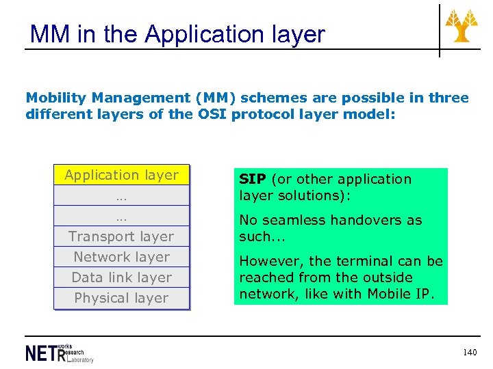 MM in the Application layer Mobility Management (MM) schemes are possible in three different layers of the OSI protocol layer model: Application layer … … Transport layer Network layer Data link layer Physical layer SIP (or other application layer solutions): No seamless handovers as such. . . However, the terminal can be reached from the outside network, like with Mobile IP. 140
 Mobility management summary Within a WLAN, handovers are possible (based on IAPP + proprietary solutions in equipment), but there is no IEEE-supported reachability solution available. Handovers between different WLANs require Mobile IP (which offers also reachability). Unfortunately, Mobile IP includes a nontransparent mechanism (Discovering Care-of Address) that must be implemented in all APs. Global reachability of wireless stations can be achieved using SIP or similar Application layer concepts. SIP does not require changes to APs. 141
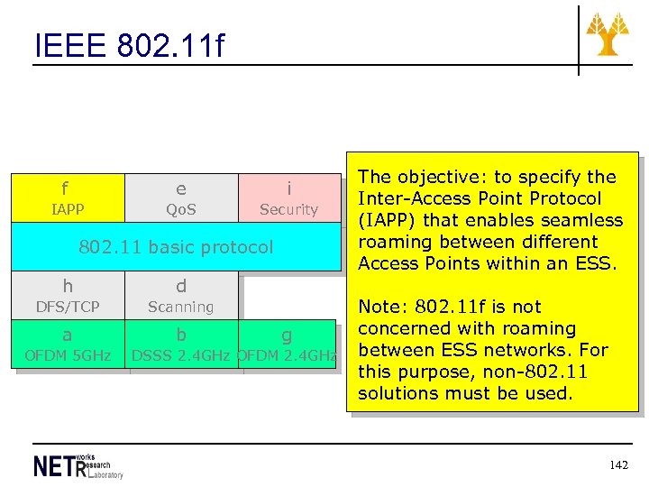 IEEE 802. 11 f f e i IAPP Qo. S Security 802. 11 basic protocol h d DFS/TCP Scanning a b OFDM 5 GHz g DSSS 2. 4 GHz OFDM 2. 4 GHz The objective: to specify the Inter-Access Point Protocol (IAPP) that enables seamless roaming between different Access Points within an ESS. Note: 802. 11 f is not concerned with roaming between ESS networks. For this purpose, non-802. 11 solutions must be used. 142
 WLAN: Design and Deployment (part of design exercise Supplemented with Slides by Mr Mylonas in Lab part) 143
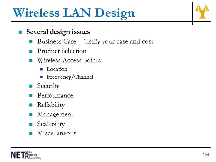 Wireless LAN Design n Several design issues n Business Case – justify your case and cost n Product Selection n Wireless Access points n n n n Location Frequency/Channel Security Performance Reliability Management Scalability Miscellaneous 144
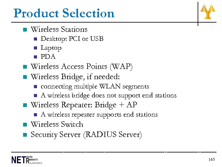 Product Selection n Wireless Stations n n n Wireless Access Points (WAP) Wireless Bridge, if needed: n n connecting multiple WLAN segments A wireless bridge does not support end stations Wireless Repeater: Bridge + AP n n Desktop: PCI or USB Laptop PDA A wireless repeater supports end stations Wireless Switch Security Server (RADIUS Server) Ref: http: //www. practicallynetworked. com/networking/wireless_bridge. htm 145
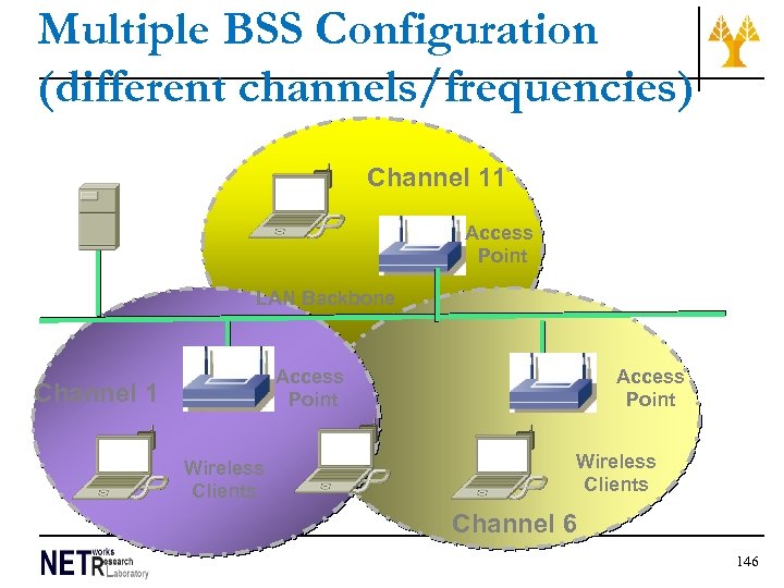 Multiple BSS Configuration (different channels/frequencies) Server Channel 11 Access Point LAN Backbone Access Point Channel 1 Wireless Clients Access Point Wireless Clients Channel 6 146
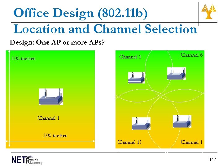 Office Design (802. 11 b) Location and Channel Selection Design: One AP or more APs? Channel 1 100 metres Channel 6 Channel 11 Channel 1 100 metres 147
 Dense populations n Case study: 1000 users in 100 mx 100 m facility n 3 or 4 APs will cover the system (in range) n Need more APs in the area than physically required? n to provide Bandwidth that is defined by customer n What side-effects are created, if any? n Interference from neighbouring units n 148
 Determining Cell Density • Cell size and throughput-based data rate will affect the cell density (maximum number of users per cell. ). • To determine cell density for a best-effort network, • determine average throughput per user • divide throughput rate of AP by throughput per user. This provides maximum active transmissions per cell. • In a best-effort WLAN, data latency does not affect the outcome. • In general, throughput will be about half the data rate of the access point.
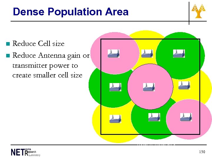 Dense Population Area Reduce Cell size n Reduce Antenna gain or transmitter power to create smaller cell size n Pink: Channel 1 Yellow: Channel 6 Green: Channel 11 100 m × 100 m area 150
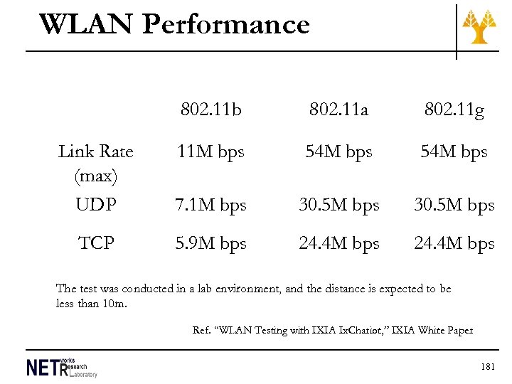
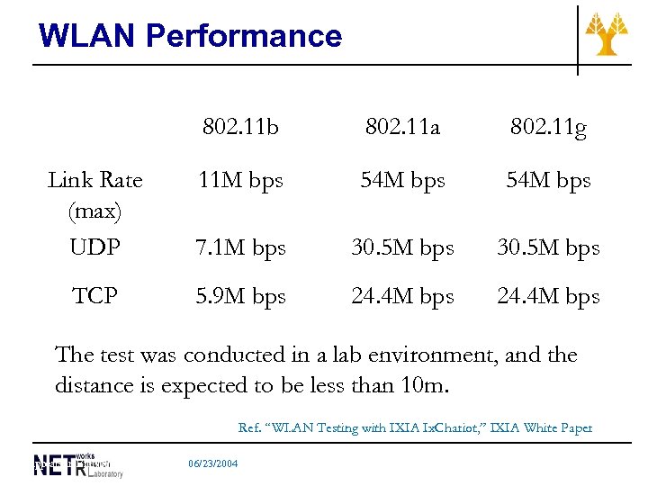 WLAN Performance 802. 11 b 802. 11 a 802. 11 g Link Rate (max) UDP 11 M bps 54 M bps 7. 1 M bps 30. 5 M bps TCP 5. 9 M bps 24. 4 M bps The test was conducted in a lab environment, and the distance is expected to be less than 10 m. Ref. “WLAN Testing with IXIA Ix. Chariot, ” IXIA White Paper Appears in Ent. Net@Supercom 2004, 06/23/2004 151
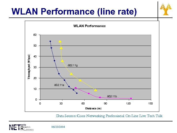 WLAN Performance (line rate) WLAN Performance 60 Throughput (Mbps) 50 40 802. 11 g 30 20 802. 11 a 10 802. 11 b 0 0 30 60 90 120 150 Distance (m) Data Source: Cisco Networking Professional On-Line Live Tech Talk Appears in Ent. Net@Supercom 2004, 06/23/2004 152
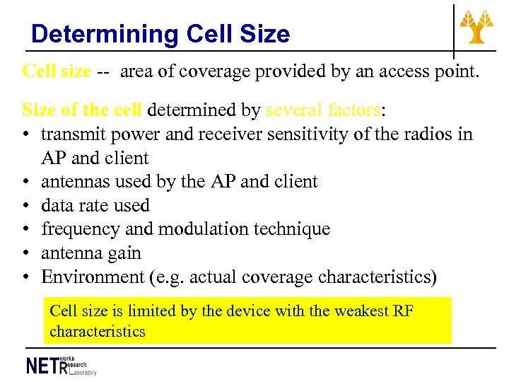 Determining Cell Size Cell size -- area of coverage provided by an access point. Size of the cell determined by several factors: • transmit power and receiver sensitivity of the radios in AP and client • antennas used by the AP and client • data rate used • frequency and modulation technique • antenna gain • Environment (e. g. actual coverage characteristics) Cell size is limited by the device with the weakest RF characteristics
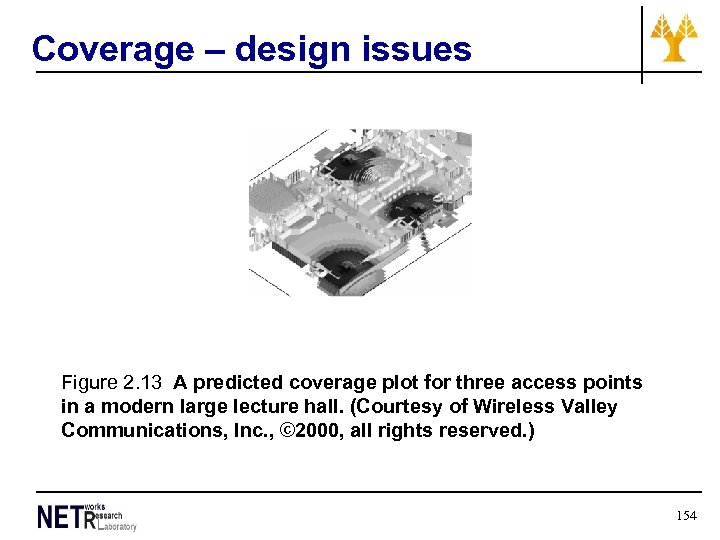 Coverage – design issues Figure 2. 13 A predicted coverage plot for three access points in a modern large lecture hall. (Courtesy of Wireless Valley Communications, Inc. , © 2000, all rights reserved. ) 154
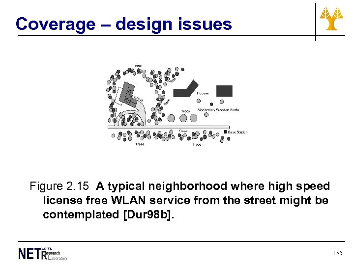 Coverage – design issues Figure 2. 15 A typical neighborhood where high speed license free WLAN service from the street might be contemplated [Dur 98 b]. 155
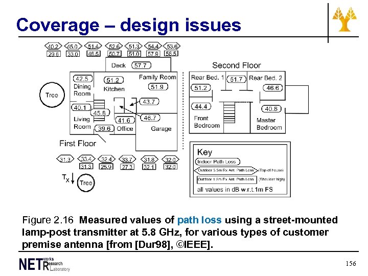 Coverage – design issues Figure 2. 16 Measured values of path loss using a street-mounted lamp-post transmitter at 5. 8 GHz, for various types of customer premise antenna [from [Dur 98], ©IEEE]. 156
 Tools for WLAN planning Many tools are available offering differing functionalities for network design, planning, and monitoring One example is: http: //www. softpedia. com/get/Network. Tools/Network-Monitoring/Net. Stumbler. shtml Another tool http: //www. metageek. net/products/inssider/ Another is http: //www. visiwave. com/index. php/Scr. Info. Product s. html? sid=Ey. Uc. Ne. Jxwly. Kb. I 46 157
 WLAN security intro 158
 WLAN Security • Not so efficient compared with Ethernet security due to the nature of the medium & the requirements of the users • Security mechanisms – Service Set Identifiers (SSID) • Used to name the network and provide initial authentication for each client – Wired Equivalent Privacy (WEP) • Data encryption technique using shared keys and a pseudorandom number as an initialization vector • 64 -bit key level encryption BUT several vendors support 128 -bit key level encryption – Wi-Fi Protected Access (WPA(2)) –replaced WEP • WPA 2 uses encryption device which encrypts the network with a 256 bit key – Also a VPN could operate on top of the WLAN providing increased security 159
 WLAN Security • IEEE newer standards – 802. 11 i (Advanced Encryption Standard – AES uses a symmetric block data encryption technique) – 802. 1 X for port based Network Access Control • provides an authentication mechanism to devices wishing to attach to LAN/WLAN (governs Extensible Authentication Protocol (EAP) encapsulation process that occurs between clients, wireless APs, and authentication servers (RADIUS) • EAP allows developers to pass authentication data between RADIUS servers and wireless APs. • has a number of variants, including: EAP MD 5, EAP-TLS, EAP-TTLS, LEAP, and PEAP 160
 WLAN Security - WEP n n Wired Equivalent Privacy (WEP) – n Least secure - A network that is secured with WEP has been cracked in 3 minutes by the FBI Shared key encryption n n Stations use the same key for encryption. RC 4 encryption algorithm Key: 40 bits or 128 bits User Authentication n Not specified in 802. 11. 802. 1 X VPN 162
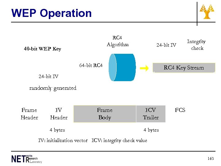 WEP Operation RC 4 Algorithm 40 -bit WEP Key 24 -bit IV 64 -bit RC 4 Integrity check RC 4 Key Stream 24 -bit IV randomly generated Frame Header IV Header 4 bytes Frame Body ICV Trailer FCS 4 bytes IV: initialization vector ICV: integrity check value 163
 WEP Key Distribution Issue n n n Key is manually set in the driver. The key cannot be protected from local users. When a user leaves the organization, technically you must change the key information on all stations. n n What if a station is stolen? For a large organization, there is a need to publish the key which is a security problem. 164
 WEP Design Issue n Weakness in the Key Scheduling Algorithm: “http: //www. crypto. com/papers/others/rc 4_ksaproc. pdf n n A weakness of RC 4 in generating the keystream. Hacker attack: using weak IV to attack a particular byte of the secret portion of the RC 4 key. The time to attack is a linear algorithm to the key length. This is a complete break for WEP. 165
 WPA(2)- Wi-Fi Protected Access n n n WPA intermediate measure to replace WEP pending availability of full IEEE 802. 11 i standard. requires firmware upgrades on wireless NICs and APs. implements much of IEEE 802. 11 i standard--adopts Temporal Key Integrity Protocol (TKIP) n TKIP employs per-packet key; dynamically generates new 128 -bit key for each packet - prevents types of attacks that compromised WEP n n n WEP used a 40 -bit or 128 -bit encryption key manually entered on wireless APs and devices and does not change. includes message integrity check to prevent an attacker from capturing, altering and/or resending data packets. WPA 2 replaced WPA. n n implements mandatory elements of IEEE 802. 11 i-- CCMP, AES based encryption mode requires testing and certification by Wi-Fi Alliance 166
 Solutions to Security Issue n Non-standard solutions Layer 3 – VPN n Layer 4 – IP Address Control and Firewall n Layer 7 –Proxy n n Standard solutions 802. 11 i (including 802. 1 X) n 802. 1 X (including EAP) n Extensible Authentication Protocol (EAP) n 167
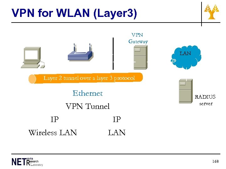 VPN for WLAN (Layer 3) VPN Gateway LAN Layer 2 tunnel over a layer 3 protocol Ethernet VPN Tunnel IP Wireless LAN RADIUS server IP LAN 168
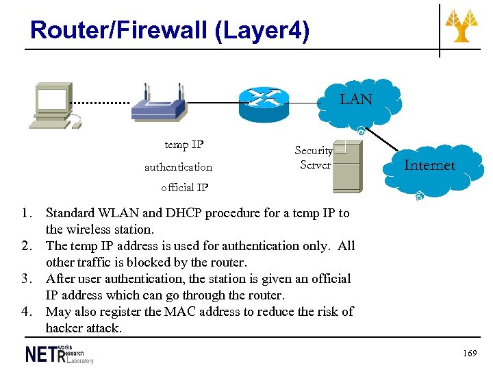 Router/Firewall (Layer 4) LAN temp IP authentication Security Server Internet official IP 1. 2. 3. 4. Standard WLAN and DHCP procedure for a temp IP to the wireless station. The temp IP address is used for authentication only. All other traffic is blocked by the router. After user authentication, the station is given an official IP address which can go through the router. May also register the MAC address to reduce the risk of hacker attack. 169
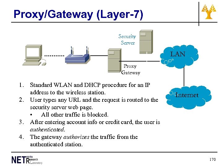 Proxy/Gateway (Layer-7) Security Server LAN Proxy Gateway 1. 2. 3. 4. Standard WLAN and DHCP procedure for an IP address to the wireless station. User types any URL and the request is routed to the security server web page. • All other traffic is blocked. After entering account info or credit card, the user is authenticated. The gateway authorizes the traffic from the authenticated station. Internet 170
 WLAN New Security Standards 802. 1 X and 802. 11 i 171
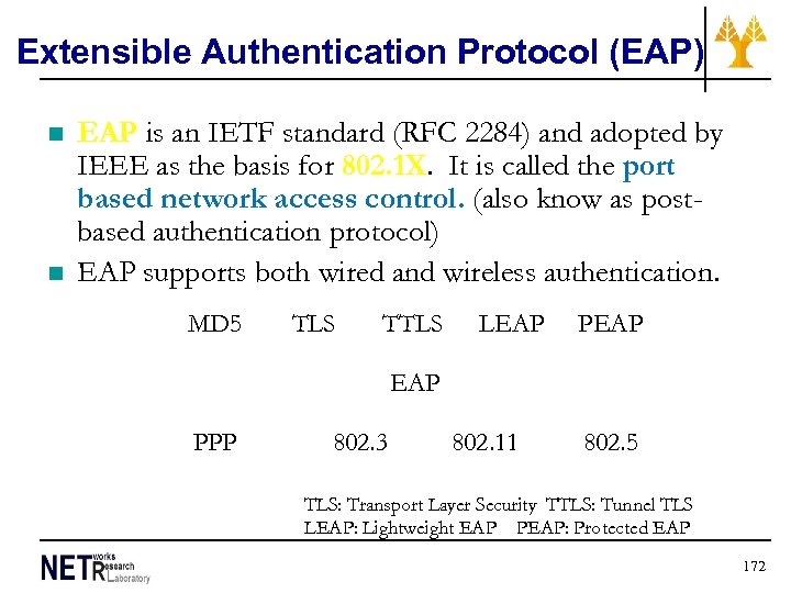 Extensible Authentication Protocol (EAP) n n EAP is an IETF standard (RFC 2284) and adopted by IEEE as the basis for 802. 1 X. It is called the port based network access control. (also know as postbased authentication protocol) EAP supports both wired and wireless authentication. MD 5 TLS TTLS LEAP PEAP PPP 802. 3 802. 11 802. 5 TLS: Transport Layer Security TTLS: Tunnel TLS LEAP: Lightweight EAP PEAP: Protected EAP 172
 EAP Authentication Methods n n n MD 5 (Message Digest 5) - Username/Password. This is similar to MS_CHAP. TLS (Transport Layer Security) - PKI (certificates), strong authentication TTLS (Tunnel TLS) - Username/Password LEAP - Cisco proprietary lightweight EAP. It is to be phased out in favor of PEAP – Protected EAP. 173
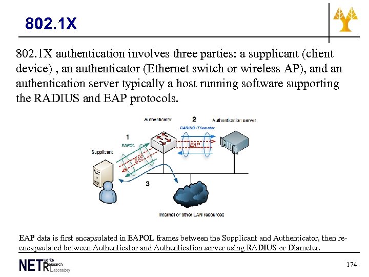 802. 1 X authentication involves three parties: a supplicant (client device) , an authenticator (Ethernet switch or wireless AP), and an authentication server typically a host running software supporting the RADIUS and EAP protocols. EAP data is first encapsulated in EAPOL frames between the Supplicant and Authenticator, then reencapsulated between Authenticator and Authentication server using RADIUS or Diameter. 174
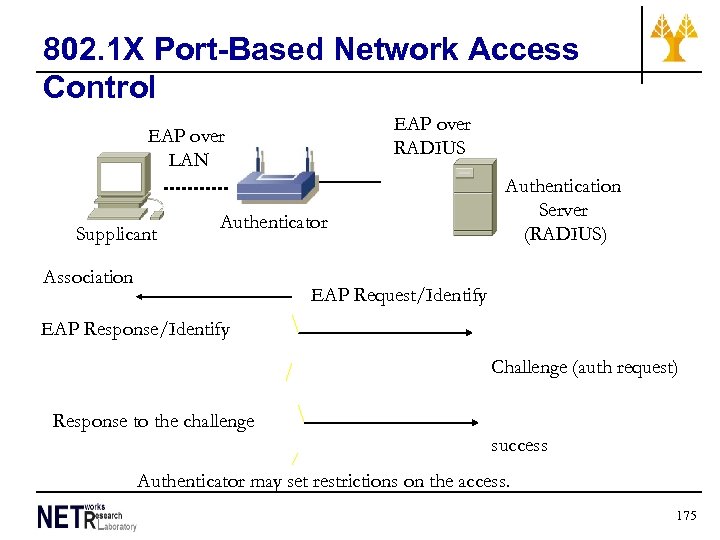 802. 1 X Port-Based Network Access Control EAP over RADIUS EAP over LAN Supplicant Authenticator Association Authentication Server (RADIUS) EAP Request/Identify EAP Response/Identify Challenge (auth request) Response to the challenge success Authenticator may set restrictions on the access. 175
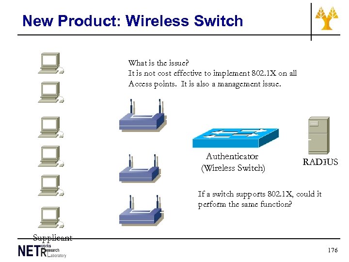 New Product: Wireless Switch What is the issue? It is not cost effective to implement 802. 1 X on all Access points. It is also a management issue. Authenticator (Wireless Switch) RADIUS If a switch supports 802. 1 X, could it perform the same function? Supplicant 176
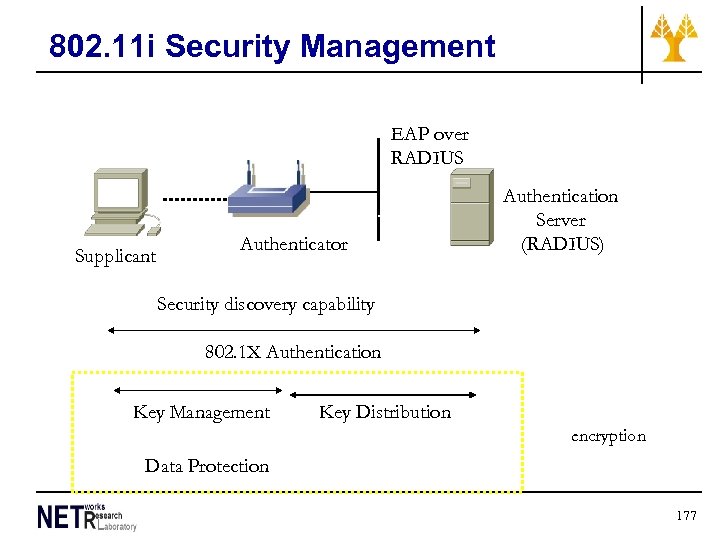 802. 11 i Security Management EAP over RADIUS EAP over LAN Supplicant Authenticator Authentication Server (RADIUS) Security discovery capability 802. 1 X Authentication Key Management Key Distribution encryption Data Protection 177
 802. 11 i Data Protection (encryption) n n Need to replace or improve WEP Wi-Fi Protected Access (WPA) and WPA 2 n n n Temporal Key Integrity Protocol (TKIP) n n n A wrapper around WEP Use MAC address to create unique key for each station. Change temporal key every 10, 000 packets It is interoperable with WEP-only device Advanced Encryption Standard (AES) n n This is included in 802. 11 i. WPA uses TKIP for encryption. This is to completely replace WEP. 802. 11 i makes use of the Advanced Encryption Standard (AES) block cipher, whereas WEP and WPA use the RC 4 stream cipher 178
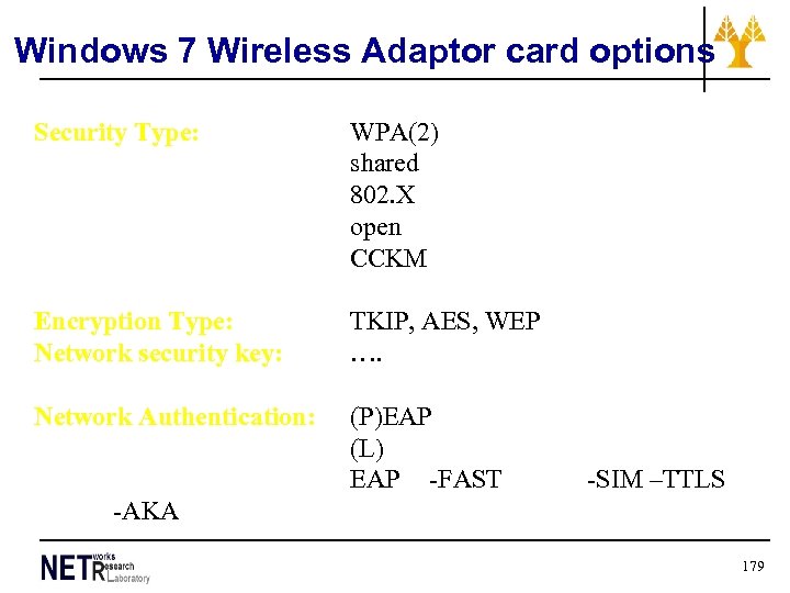 Windows 7 Wireless Adaptor card options Security Type: WPA(2) shared 802. X open CCKM Encryption Type: Network security key: TKIP, AES, WEP …. Network Authentication: (P)EAP (L) EAP -FAST -SIM –TTLS -AKA 179
 WLAN enhancements 180
 WLAN Performance 802. 11 b 802. 11 a 802. 11 g Link Rate (max) UDP 11 M bps 54 M bps 7. 1 M bps 30. 5 M bps TCP 5. 9 M bps 24. 4 M bps The test was conducted in a lab environment, and the distance is expected to be less than 10 m. Ref. “WLAN Testing with IXIA Ix. Chariot, ” IXIA White Paper 181
 WLAN enhancements • See paper WLAN enhancements Performance enhancement of WLANs Methods for improving WLANs performance employ: • Enhanced hardware in the Physical Layer to achieve better physical (PHY) layer parameters, such as shorter Slot Time and shorter Short Inter-Frame Space (SIFS). • Better tuning of WLAN parameters, such as Fragmentation Threshold and RTS Threshold [2]. • Adaptive (rather than basic) back-off algorithms in the MAC layer]. • Proxy approaches in the link-layer, such as snoop protocol. • Split-connection approaches, such as I-TCP or M-TCP 182
 IEEE 802. 11 – enhancements • IEEE 802. 11 e – MAC enhancements for providing some Qo. S • No Qo. S in the DCF operation mode • Some Qo. S guarantees can be given only via polling using PCF • For applications such as audio, video, or media stream, distribution service classes have to be provided – For this reason, MAC layer must be enhanced 183
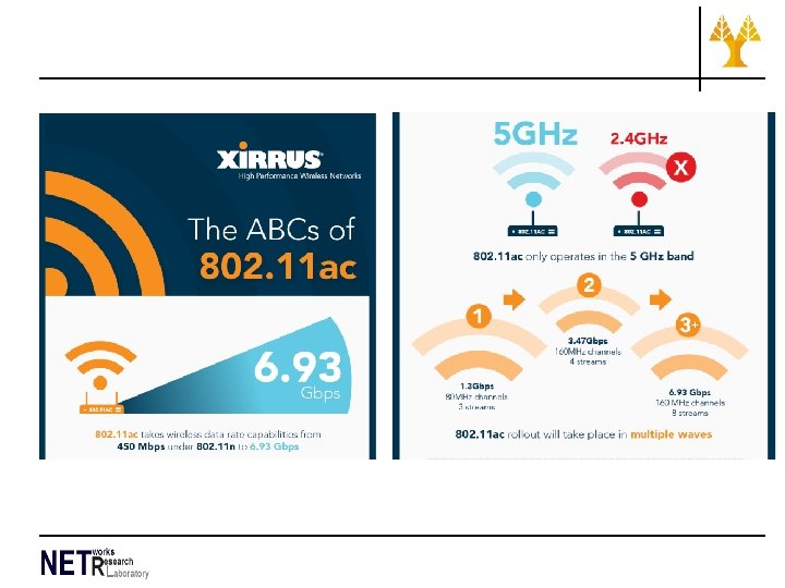
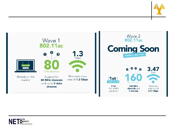
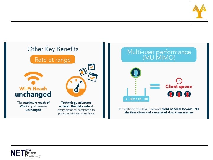
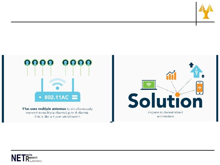
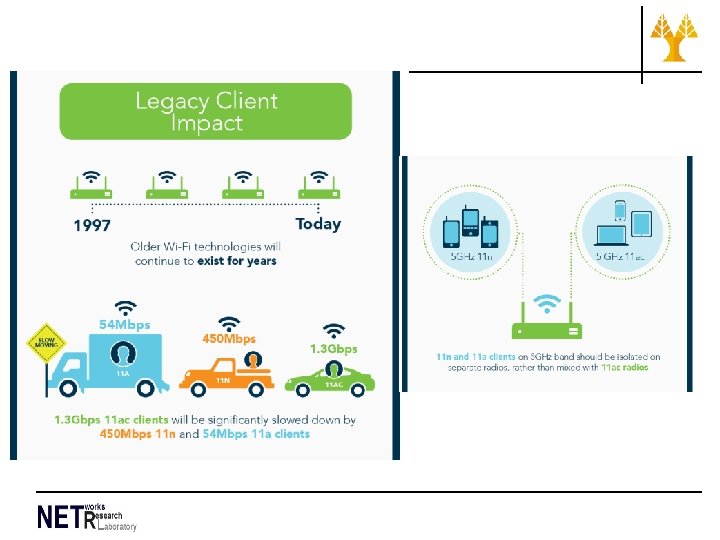
 WLAN new technologies 802. 11 ac Based on Xirrus http: //wifi. xirrus. com/abcs 11 ac? elq=502 ceecd 98 ba 417 d 93 b 3514 b 0 bb 15391&elq. Campaign. Id=29 184
