

ae5bf2a67dbcb352ff26964c1a731d3a.ppt
- Количество слайдов: 79
![WEL COME PRAVEEN M JIGAJINNI PGT (Computer Science) MCA, MSc[IT], MTech[IT], MPhil (Comp. Sci),](https://present5.com/presentation/ae5bf2a67dbcb352ff26964c1a731d3a/image-1.jpg "WEL COME PRAVEEN M JIGAJINNI PGT (Computer Science) MCA, MSc[IT], MTech[IT], MPhil (Comp. Sci),") WEL COME PRAVEEN M JIGAJINNI PGT (Computer Science) MCA, MSc[IT], MTech[IT], MPhil (Comp. Sci), PGDCA, ADCA, Dc. Sc. & Engg.
WEL COME PRAVEEN M JIGAJINNI PGT (Computer Science) MCA, MSc[IT], MTech[IT], MPhil (Comp. Sci), PGDCA, ADCA, Dc. Sc. & Engg.
 Reference Book CLASS XI By Sumita Arora
 Chapter - 4 INPUT, OUTPUT & STORAGE DEVICES
 MACHINE-READABLE FORM ü The form in which data is readable to the input unit of the computer is called as machine-readable form. ü The data in machine-readable form is read by an input unit, transformed to appropriate internal code and stored in computer’s memory.
 INPUT UNIT ü The input unit is responsible for accepting i. e. data and instructions from the user. ü There are many input devices as of today. ü Here we take an overview of some common and popular devices. (viz. keyboard, mouse, mic).
 THE KEYBOARD ü Its like a typewriter like device which is used to type in the letters, digits and commands. ü It contains a matrix of switches (1 switch /key). ü Each pressed key sends a digital code to that determines which key has been pressed. ü Computers decodes the digital code and determines the pressed key.
. May") THE MOUSE ü A pointing device ü Has two or three buttons (generally). May (not) have wheel. ü A mouse pointer follows the movements of the mouse. ü !!!!!!!the mouse was invented by Douglas Engelbart of Stanford Research Centre in 1963.
THE MOUSE ü A pointing device ü Has two or three buttons (generally). May (not) have wheel. ü A mouse pointer follows the movements of the mouse. ü !!!!!!!the mouse was invented by Douglas Engelbart of Stanford Research Centre in 1963.
 ü (Microphone) a special device which sends sound input to the computer.") THE MICROPHONE(MIC) ü (Microphone) a special device which sends sound input to the computer. ü A mic converts the sound received into computer’s format which is digitized sound/audio. ü A mic can work if a computer has a special hardware known as sound card.
THE MICROPHONE(MIC) ü (Microphone) a special device which sends sound input to the computer. ü A mic converts the sound received into computer’s format which is digitized sound/audio. ü A mic can work if a computer has a special hardware known as sound card.
 OUTPUT DEVICES ü Devices which produces output to the user. ü There can be various form of results and different devices for each different kind. ü Here we learn about monitors, printers, speakers.
 MONITORS ü Monitor or screen is the most common form of output from a computer. ü It displays results similarly to a television. ü The most commonly used today are q Cathode Ray Tube q Liquid crystal display
 CATHODE RAY TUBE ü It works similar to a TV. ü Has an electron-gun which fires electron at groups of phosphor dots, which coat inside of the screen. ü When they strike the screen the resulting images are formed on the screen.
 LIQUID CRYSTAL DISPLAY ü Liquid crystal is the material used to create each pixel; on the screen. ü The material has special property of polarizing light depending upon the electrical charge across it. It allows the pixels to be formed. ü Each tiny cell of liquid crystal display is a pixel.
 TFT- THIN FILM TRANSISTOR ü Thin film transistor is the device within each pixel that sets the charge.
 PRINTERS ü Printers give hard copies of output. ü Printers can be classified into two categories: -1. Impact printers 2. Non impact printers
 IMPACT/NON-IMPACT ü Impact printer-in these printers there is a mechanical contact between the print head and paper. ü Non-impact printer- In these printers there is no mechanical contact between printhead and paper.
 IMPACT PRINTER ü Impact Printers come in various categories: 1. Dot matrix printers 2. Line printers 3. Drum printers 4. Daisy wheel printers • Most common of all these is dot matrix printers.
 DOT MATRIX PRINTERS ü It is the most popular serial printer (prints one character at a time). ü The print head contains a vertical array of pins. ü When selected pins fire against an inked ribbon desired material is printed on the paper by these dots.
 NON-IMPACT PRINTERS ü The natural limitations and cost of the impact printers have led to the development of the non -impact printers. ü These can primarily be categorized in these types: 1. Electromagnetic printers. 2. Thermal printers. 3. Electrostatic printers. 4. Inkjet printers. 5. Laser printers.
 ELECTROMAGNETIC PRINTERS • A magnetic image of what is to be printed is recorded on a drum surface and this surface is passed through magnetic powder which adheres to the charged areas and then is pressed on to the paper. • It speeds up to 250 cps.
 THERMAL PRINTERS üAn electric pulse can be converted to heat on selected sections of printing heads or nibs or wires. When this heat is applied to heat sensitive paper a character is printed.
 ELECTROSTATIC PRINTERS ü For electrostatic printers the paper is coated with a non-conducting dielectric material which holds charges when voltages are applied to it with writing nibs. ü These heads writes dots on paper when it passes. ü Then the paper passes through a toner colored material charged oppositely wrt the on the dots. As a result the particles adheres to the oppositely charged areas and hence, the characters are printed.
 INKJET PRINTERS ü A stream of ink with high velocity is directed towards paper which is deflected by an electrostatic field. Some other printers of this kind breaks the stream into droplets by an ultra sonic transducer.
 LASER PRINTERS ü The desired output image is written on a copier drum with the help of a light beam controlled by a computer. ü With this certain parts of drum gets electrically charged, then this drum surface is exposed to a laser beam. ü The laser exposed areas attract a toner which attaches itself to the charged areas generated by the laser beam and thus the image is formed. ü These are capable of producing very high point quality and can print 10 -15 pages per minute.
 SPEAKERS ü Speakers receive sound in electric current form from the sound-card and then converts it back into sound format.
 THE MEMORY DEVICES ü Memory is an essential part of every computer. ü By now you must have known that RAM is the main memory of computer.
 MEMORY ORGANIZATION ü A given memory is divided into N words where each word is assigned an address in the memory. ü The number of bits, a memory word consists of, is known as word length.
 MEMORY ADDRESS ü Memory addresses are simply consecutive numbers, starting from 0 to the largest number. ü At address 0 we find the first word and at 1 we find the second one and so on.
 THE DIFFERENCE ü There is a difference between memory contents and memory address. ü It can be illustrated by considering a cabinet having as many drawers as many as addresses. ü Now contents are the material inside the drawer and the no. of drawer is the address.
 READ/WRITE ü When we read we don’t destroy the contents at an address, so we call it as Non-Destructive Read. ü but when we write to a memory address it in fact overwrites the pre-existing content or we can say replaces the previous contents; so we call it as Destructive Write.
 ü A memory with 4096 locations with each location having 19") CALLING NAMES (MEMORY) ü A memory with 4096 locations with each location having 19 -bits is called a 4096 word 16 -bit memory, or 4 K 16 -bit memory, (1 K=1024). ü Memories can be both read and written into. ü These memories are called as Read-write memory. ü Some memories have programs permanently stored on them; these are known as read only memory.
CALLING NAMES (MEMORY) ü A memory with 4096 locations with each location having 19 -bits is called a 4096 word 16 -bit memory, or 4 K 16 -bit memory, (1 K=1024). ü Memories can be both read and written into. ü These memories are called as Read-write memory. ü Some memories have programs permanently stored on them; these are known as read only memory.
 ü Main memory can be classified into two categories:") THE MAIN MEMORY (PRIMARY MEMORY) ü Main memory can be classified into two categories: 1. RAM (Random Access Memory) 2. ROM (Read Only Memory)
THE MAIN MEMORY (PRIMARY MEMORY) ü Main memory can be classified into two categories: 1. RAM (Random Access Memory) 2. ROM (Read Only Memory)
 the memory cells can") RANDOM ACCESS MEMORY ü In the random access memory (RAM) the memory cells can be accessed for information transfer from any desired location. That is, the process for locating a word in memory is the same and requires an equal amount of memory, thus the name “Random Access”.
RANDOM ACCESS MEMORY ü In the random access memory (RAM) the memory cells can be accessed for information transfer from any desired location. That is, the process for locating a word in memory is the same and requires an equal amount of memory, thus the name “Random Access”.
 RAM TALK ü RAM communicates with its environment with the help of data input and output lines, address selection lines, and control lines that specify the direction of transfer. n data input lines k address lines Read Control lines Write Memory unit 2 k words n bits per word n data output lines
 2. Static RAM (SRAM)") TYPES OF RAM 1. Dynamic RAM (DRAM) 2. Static RAM (SRAM)
TYPES OF RAM 1. Dynamic RAM (DRAM) 2. Static RAM (SRAM)
 DYNAMIC RAM ü DRAM consists of a transistor and capacitor that’s capable of storing an electric charge. It depends upon switch whether it stores 0 or 1. ü The charge on the capacitor tends to leak-off, provision is made to periodically segment or refresh the storage charge. ü The point above is a clear pointer to how is RAM volatile. ü (volatile means contents are lost when no power. )
 INSIDE DRAM ü A typical DRAM cell consists of only two elements a MOSFET (Metal Oxide Semiconductor Field Effect Transistor) switch and a capacitor storing a bit. ü DRAM cell consumes very less power and is able to sustain high frequency of switching operations.
 MEMORY ACCESS TIME ü The time taken in producing data required from memory (from the start of access to the availability of data ) is called as memory access time. ü It is sometimes abbreviated as t. AC. ü General access time of today’s DRAM is 770 nanoseconds.
 DRAM STORAGE DENSITY ü Since DRAM consists of only one transistor and capacitor per bit, it allows a DRAM chip to pack a large number of cells within itself wrt to SRAM. ü Generally DRAM chips are available with 128 bit or 256 bit densities or even more.
 DRAM REFRESHING ü DRAMs come in various designs: 1. EDO DRAM 2. SDRAM 3. RDRAM 4. DDRDRAM
 • Conventional DRAM cells discharge after each read operation") EDO RAM (extended data out) • Conventional DRAM cells discharge after each read operation and requires refreshing time before it can be read again. • But an EDO RAM cell keeps its data valid until it receives an additional signal. • It has a dual pipeline architecture, which allows the memory controller to simultaneously read new data while discharging the old. As a result the system doesn’t have to wait for a separate read cycle, but can read or write data immediately as soon as address bits are supplied to the chip.
EDO RAM (extended data out) • Conventional DRAM cells discharge after each read operation and requires refreshing time before it can be read again. • But an EDO RAM cell keeps its data valid until it receives an additional signal. • It has a dual pipeline architecture, which allows the memory controller to simultaneously read new data while discharging the old. As a result the system doesn’t have to wait for a separate read cycle, but can read or write data immediately as soon as address bits are supplied to the chip.
 SDRAM ü Synchronous DRAM. Because of multiplexing, EDO DRAM chips cannot operate in lock-step with their host microprocessors. ü Such asynchronous memory performances keep the memory bus speed limited to 66 MHz. ü But with the advent of faster processor a need was felt to optimize the speed of the ram chips. ü To make it happen the chip was redesigned to make the chip sync with processor so that it could deliver data in each clock cycle. ü These are what we call as Synchronous DRAM.
 RDRAM • Rambus DRAM. It has addressed some of the complex physical and electric problems involved with memory. • It doesn’t multiplex or share control info on the data bus; rather it creates an independent control and address bus split into two groups of pins for row and column commands. And data is transmitted across 16 -bit wide data bus. • Synchronization is achieved by sending packets on the falling of the clock.
 DDR SDRAM ü DOUBLE DATA RATE DRAM. ü Unlike SDRAM that supports 1 operation in each clock cycle, the DDR SDRAM memory does 2 operations per clock cycle thus doubling the amount of data flow wrt SDRAM (single data rate).
 STATIC RAM ü Static RAM is also volatile but it doesn’t require any special regenerative circuit to retain the stored data. ü It has flip-flops that store the binary info. ü The stored info remains valid as long as power is supplied to the unit.
 STATIC vs. DYNAMIC ü Static RAM takes up more space for a given storage capacity than a DRAM. ü SRAM are used in specialized applications whereas DRAM is used in general applications. ü The SRAM is easier to use and has shorter read/write cycles wrt DRAM.
 ü Its name cries it cannot write but can read") ROM (Read Only Memory) ü Its name cries it cannot write but can read only. ü Clearly, data stored must be permanent. ü The information it carries is embedded into the unit to form the required interconnection pattern. ü ROMs come with special internal electronic fuses which can be “programmed” for a specific configuration. ü Once the pattern is established it remains in it even if power supply is NOT AVAILABLE.
ROM (Read Only Memory) ü Its name cries it cannot write but can read only. ü Clearly, data stored must be permanent. ü The information it carries is embedded into the unit to form the required interconnection pattern. ü ROMs come with special internal electronic fuses which can be “programmed” for a specific configuration. ü Once the pattern is established it remains in it even if power supply is NOT AVAILABLE.
 TYPES OF ROM • 1. 2. 3. The types of ROM are: PROM EEPROM
 PROM • Programmable read only memory. Using PROM-program facility a PROM can be programmed and later on its content can be altered i. e. it becomes same as a ROM.
 EPROM ü Erasable programmable read only memory. ü It can be REPROGRAMMED using PROM-program facility. ü Erasure is achieved by exposing this chip to UV light. ü It comes in 2 varieties: 1. UPROM(ULTRAVIOLET PROM) 2. EAPROM(ELECTRICALLY PROM) ALTERABLE
 EEPROM ü ELECTRICALLY ERASABLE PROM. ü PROM which can be electrically programmed (NO UV required). ü It certainly has double advantage of storing temporary& permanent data. ü Now a days a winsome couple (with RAM ) is being used by manufacturing unit. ü When RAM looses its memory in case of a power failure its partner lends a helping hand (as EEPROM can retain its data without any power as well ).
 CACHE The cache memory is a high speed memory available inside CPU in order to speed up access to data and instructions stored in RAM memory.
 CACHE MEMORY • Pronounced as “cash” • It’s a special high speed storage mechanism. • It can be either a reserved section of main memory or an independent high-speed storage device. • Whenever a piece of data is required the processor first looks into cache.
 CACHE STORE ü A memory cache, sometimes called a cache store or RAM cache, is a portion of main memory made of high-speed SRAM. ü You must have by now known about efficiency of cache –BUT why? ü Simply because all the programs keep looking same data or instructions over and over again & if these can be cached as much as possible, definitely the performance will be upscaled noticeably.
 WHERE CACHE? ü Some memory caches are built into the architecture of microprocessors. ü For ex. — ü Intel Quad Q 6600 microprocessor contains an 128 KB memory cache. ü Such caches are known as level 1(L 1) cache. ü Most modern PCs come with external cache. These are known as level 2 (L 2) cache. ü These caches sit necessarily between CPU & DRAM. ü Both caches (L 1, L 2) are composed of SRAM but L 2 caches are much larger.
 DISK CACHING ü Disk caching uses the same mechanism but instead of storing the required data on L 1/L 2 memories it caches the most recently used and neighboring sectors on a buffer in RAM. ü Needlessly accessing data from RAM is 1000 &a few notches more faster than from HD. ü It dramatically enhances the speed of the processing as data to the processor is reached extremely fast.
 THE SECONDARY MEMORY DEVICES ü You know very well about the volatility and lessstorage capacity of primary memories. ü A secondary storage is needed to settle the issue. ü Secondary storage devices store permanently and have a lot of room for all you data and info. ü If you still feel new to the term you should recall that HD of your computer is a secondary storage device.
 COMMMON STORAGE DEVICES ü Hard disks ü Floppy disks MAGNETIC MEDIA ü CCD ROMs ü DVDs OPTICAL MEDIA ü The capacity of these storage devices is measured in KBs, MBs, GBs, TBs.
 ü One of the oldest portable storage devices used to transfer") FLOPPY DISK (DISKETTE) ü One of the oldest portable storage devices used to transfer a small amount of data from one computer to another. ü A floppy disk is made of Mylar (a flexible substance). ü A standard floppy disk can store upto 1. 44 Mb of data which is equivalent to 300 A 4 pages of text.
FLOPPY DISK (DISKETTE) ü One of the oldest portable storage devices used to transfer a small amount of data from one computer to another. ü A floppy disk is made of Mylar (a flexible substance). ü A standard floppy disk can store upto 1. 44 Mb of data which is equivalent to 300 A 4 pages of text.
 FORMATTING ü All disks must be formatted before data can be written onto them. ü Formatting means marking and dividing the disk into tracks and sectors. ü The floppy disk is divided into many concentric circles known as tracks. ü Each track is further subdivided into smaller sections called sectors.
 HARD DISKS ü The hard disks have 1 or more platters on which the data is stored. ü These platters rotate and are coated with a magnetic material and stacked with spaces between them. ü Info is recorded on these by magnetic heads on tiny magnetic spots. ü These heads are mounted on access arms. ü Info is recorded in bands. Each band of info on a given disk is called a track.
 TRACKS AND SECTORS ü Hard disks are also divided in tracks and sectors. ü Tracks are again concentric circles (as in the case of floppies) and sectors are pie shaped sections of tracks. ü In most systems, the minimum quantity of information which can be transferred is a sector. ü But these divisions are invisible.
 TYPES EXPLAINED 1. CD-ROM: -used only to store information not data. They come with a reported speed (48 x 75 x). 2. CD-R: - these can be written onto only once though you can write it in multiple sessions. 3. CD-RW: -you can write and read so many times on these disks.
 COMPACT DISKS • • CDs as they are familiarly called are a commonplace among other optical medias of data storage. They are mainly of three types: 1. CD-ROM (Compact Disk Read Only Memory) 2. CD-R (Compact Disk -Recordable) 3. CD-RW (Compact Disk-recordable)
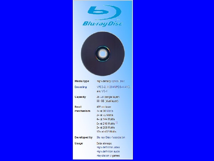
 DVD ü It is an optical storage device same as CDs but can store 15 times of data & can transfer 20 faster than CD-ROM. ü A DVD also called Super Density Disk (SD) upto 17 GBs of data or 4 hours of movies on a side. Sides Layers Storage capacity 1 1 2 2 1 2 4. 7 GB 8. 5 GB 9. 4 GB 17 GB
 TYPES OF DVDS ü DVDs also come in tree varieties: 1. DVD-ROM (Digital Video Disk-read Only Memory) 2. DVD-R (Digital Video Disk-recordable) 3. DVD-RW (Digital Video Disk-Rewritable)
 TYES EXPLAINED ü DVD-ROM: -optical disk can Store 4. 7 -17 GB were originally developed for movie industry. ü DVD-R: -can be written once and then read as longer as they are alive. ü DVD-RW: -it can be written many times. These in addition to CDs come in 2 additional formats + &.
 PORTS • Ports are used to connect external devices to the computer. There are several types of ports: 1. Serial ports 2. Parallel ports 3. USB (Universal Serial Bus)
 SERIAL PORTS ü The serial port transfers serially 1 bit at a time. ü As a result it needs only wire to transmit 8 bits. ü The disadvantage is that it takes 8 times longer to transfer 1 byte. ü It is also necessary that a start, stop an parity bit is sent to mark start end and integrate the sent data. ü These come in the form OF 9 -PIN or 25 -PIN male connector. They typically connect devices like modem and mouse are often referred to as communication (COM) ports or RS 232 C ports.
 PARALLEL PORTS ü Parallel ports can send or receive data @ 8 bits at a time, all the bits(8) transmitted parallel to each other. ü Parallel ports come in the form of 25 -pin female connector. ü These ports are used while connecting printers, scanners, mice, joystick, digital cameras, zip drives, external HDs, tape backup drive, etc.
 USB • UNIVERSAL SERIAL BUS. • To spare the botheration of using the above mentioned male & female connectors, the USB has been designed. • It gives you a single, standardized, easy-to-use way to connect various devices to the computer. • These devices are printers, scanners, joysticks, etc.
 AGP ü ACCELERATED GRAPHICS PORT is used to connect graphics card to the computer which provide high-speed video performance typically required in gaming & other multimedia applications.
 IR PORT • INFRA RED ports send and receive IR signals to/from other devices. • It’s gained a lot of popularity very recently with the advent of laptops and other wireless gadgets.
 IR TECH • It uses the technology of remote controllers (like one used with TV sets ). • IR signals are modulated with information and can send it to shorter distances. It involves a transceiver (transmitter+ receiver) placed in a chip. Special software is required to sync the communication. • Max effective range is 1. 5 miles and max bandwidth 16 Mbps. It’s line of sight light transmission so fog & other atmospheric conditions have their effects.
 BLUETOOTH • Bluetooth telecommunications industry specification that describes how mobile phones, computers and PDAs can be easily interconnected using a short range wireless connection. • Bluetooth requires a low-cost transceiver chip be placed in the devices communicating. • It uses a previously unused 2. 45 GHz which is available globally (except some local variations). • In addition to data it can accommodate 3 voice channels.
 TRUE BLUE …. ü Each device has a unique 48 -bit address from the IEEE 802 standard. ü It can have point to point or multi-point connections with a bandwidth of 1 Mbps(2 Mbps in 2 nd gen. ) within a range of 10 meters. ü A frequency hop scheme allows it to operate even in areas of high electromagnetic interference. ü Built in encryption and verification is provided. ü The technology has got its name in honour of Harald Bluetooth, king of Denmark in the mid-tenth century.
 PS-2 PORT • The PS/2 standard, introduced by IBM in 1987, stands for Personal System/2. • A PS/2 port is an electronic receptacle or plug found on computers. it accepts a PS/2 cable with a mini-DNIN connector, and is most often used to plug-in keyboard or mouse. • The PS/2 is female while DIN cable is male. The connector is small with a diameter of 1/3 inch (9. 5 mm). It features a metal sleeve that is notched to ensure proper plugging into PS/2 port. This ensures that pins of DIN doesn’t bend. Used generally with keyboards.
 DIN • DIN is short for Deutsches Insitut Fur Normung Ev, the standard setting organization for Germany. • A DIN connector is ac connector which conforms to one of the many standards defined by DIN. • These are widely used in PCs.
 THANK YOU