

d3ec6a51e7442619541309cd848e9e68.ppt
- Количество слайдов: 34
 Utilizing Drones to Create Professional Quality 3 D Models VANCE MOORE, GARRETT & MOORE
 What are Professional Quality 3 D Models? Dense Point Clouds 3 D Polygonal Mesh (Triangulated Irregular Network, or TIN) DEM- Digital Elevation Model DSM - Digital Surface Model. Data includes vegetation, structures, etc. DTM - Digital Terrain Model. Data removes vegetation and structures (i. e. bare earth) Orthomosaic Image that can be used to measure true distances.
 Small Unmanned Aircraft Requirements Remote pilot airman certificate (commercial) Must") FAA Regulations (Part 107) Small Unmanned Aircraft Requirements Remote pilot airman certificate (commercial) Must keep your drone within sight Maximum allowable altitude is 400 feet above the ground (higher if your drone remains within 400 feet of a structure) Can’t fly over anyone who is not directly participating in the operation. Avoid manned aircraft
FAA Regulations (Part 107) Small Unmanned Aircraft Requirements Remote pilot airman certificate (commercial) Must keep your drone within sight Maximum allowable altitude is 400 feet above the ground (higher if your drone remains within 400 feet of a structure) Can’t fly over anyone who is not directly participating in the operation. Avoid manned aircraft
 Modelling Process Turns camera based images to accurate, georeferenced 2 D maps and 3 D models. Do not crop or geometrically transform, i. e. resize or rotate, the images. Using RAW data losslessly converted to the TIFF. JPG compression may induce unwanted noise to the images.
 Equipment – Digital Camera Appropriate Resolution Appropriate focal length Fixed lenses are preferred. Avoid ultra-wide angle and fisheye lenses. Sufficient Shutter Speed to Avoid Blur
 “Fisheye” Lens Commonly found on the Go. Pro camera Causes a warped look Original “De-Fished”
 Equipment - Drone Sufficient Payload & Flight Time Programmable Flight Paths Programmable Camera Triggering
 Image Geometry
 Image Geometry Image Length Image Width Flight Direction
 Sensor Length = 23. 6") Image Geometry Sony R 10 C Camera (20 MP) Sensor Length = 23. 6 mm (5, 456 pixels) Sensor Width = 15. 7 mm (3, 632 pixels) Focal length = 20 mm
Image Geometry Sony R 10 C Camera (20 MP) Sensor Length = 23. 6 mm (5, 456 pixels) Sensor Width = 15. 7 mm (3, 632 pixels) Focal length = 20 mm
 Image Geometry - R 10 C Flight Path
") Image Geometry - R 10 C Flight Path (Into Page)
Image Geometry - R 10 C Flight Path (Into Page)
 Image Geometry - R 10 C ~ 400 Ft Image Length ~ 470 Ft Image Width ~ 312 Ft
 The Ground Sampling Distance (GSD) is the distance between two") Ground Sample Distance (GSD) The Ground Sampling Distance (GSD) is the distance between two consecutive pixel centers measured on the ground. The higher the altitude of the flight, the bigger the GSD value. The bigger the value of the image GSD, the lower the spatial resolution of the image and the less visible details.
Ground Sample Distance (GSD) The Ground Sampling Distance (GSD) is the distance between two consecutive pixel centers measured on the ground. The higher the altitude of the flight, the bigger the GSD value. The bigger the value of the image GSD, the lower the spatial resolution of the image and the less visible details.
") Ground Sample Distance (GSD)
Ground Sample Distance (GSD)
 (~400 Ft) Camera resolution effects on GSD Go. Pro R") Ground Sample Distance (GSD) (~400 Ft) Camera resolution effects on GSD Go. Pro R 10 C
Ground Sample Distance (GSD) (~400 Ft) Camera resolution effects on GSD Go. Pro R 10 C
 Modelling Process Objects to be reconstructed must be visible on at least two photos. In case of aerial photography, ~75% forward image overlap and ~60% side image overlap Flight Path will have straight and parallel flight lanes for pictures to ensure picture overlap
 75% Forward Image Overlap
 75% Forward Image Overlap @400 FT Flight Height Flight Path
 60% Side Overlap
 Flight Path (Out") 60% Side Overlap @400 FT Flight Height Flight Path (Into Page) Flight Path (Out of Page)
60% Side Overlap @400 FT Flight Height Flight Path (Into Page) Flight Path (Out of Page)
") Planning a Mission Determine area to be modeled Determined desired model accuracy (flight height) Frequency of Pictures (Forward Overlap) Number of flight paths (Side Overlap) Location for the flight takeoff point Minimum and maximum heights above surface. Control Panel Layout
Planning a Mission Determine area to be modeled Determined desired model accuracy (flight height) Frequency of Pictures (Forward Overlap) Number of flight paths (Side Overlap) Location for the flight takeoff point Minimum and maximum heights above surface. Control Panel Layout
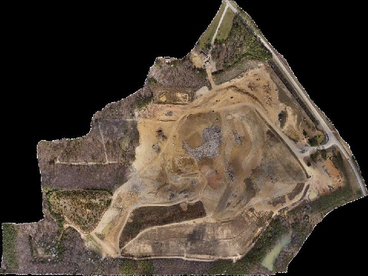
 Target Area Example
 Choosing the Correct Take Off Point Choosing the correct take off point will allow you to make the flight as efficient and effective as possible Choose a point as roughly as close to the middle as possible while picking a balance between a high and low take off point Getting the right location will save flight time, and get the best picture quality (coverage and resolution)
 (Out of Page)") High Take Off Point Side Overlap Flight Path (Into Page) (Out of Page)
High Take Off Point Side Overlap Flight Path (Into Page) (Out of Page)
 (Out of Page)") Low Take Off Point Side Overlap Flight Path (Into Page) (Out of Page)
Low Take Off Point Side Overlap Flight Path (Into Page) (Out of Page)
 High Take Off Point Forward Overlap Flight Path
 Low Take Off Point Forward Overlap Flight Path
 High vs Low Take Off Point High Take-Off Point Low Take-Off Point Pros: Adequate Image Overlap Fewer Images Larger area coverage for flight time Cons: Lower GSD Higher GSD Cons: Image Overlap Issues? More Images Less area coverage for flight time
 Control Points The model’s accuracy depends on the number, distribution, and measured accuracy of the GCPs. Relative Accuracy : Defined by comparing individual features on a map / reconstructed model / orthomosaic with other features on the same model. (Site Control) Absolute Accuracy : Defined by the difference between the location of features on a map / reconstructed model / orthomosaic and their true position on the Earth.
 Control Point Example
 Imaging Process
 Final Product https: //youtu. be/Pn. SU 2 d_y. PS 0