

 DUSEL scintillator meeting")
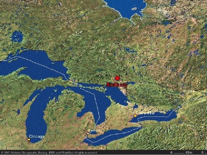
Use of large volume scintillator at SNOLAB Richard Ford (SNOLAB, Sudbury) DUSEL scintillator meeting August 10 th 2006, Fermilab, Chicago http: //www. snolab. ca

Use of large volume scintillators at SNOLAB • • • Introduction to SNOLAB SNO+ (the experiment with the scintillator) Scintillator purification and the plants Planned operations with scintillator Scintillator plant design and construction (requirements, regulations, approach) • Fire protection design and construction (requirements, regulations, approach)

Deep Underground Laboratories Creighton Nickel Mine and SNOLAB

SNOLAB – Mining for Knowledge Surface Facility INCO’s Creighton Mine #9 Shaft 2 km overburden (6000 mwe) Underground Laboratory

SNOLAB Underground Facility Utilities include: * Personnel facilities * Sewage plant * Facility and plant control systems * UG railroad for material transport * 2 MW power (600 V 3 -phase) * 1 MW cooling (5 chillers) * Ultra pure water plant * Boil-off nitrogen * Compressed air * Vent and burst headers * Fire water reserve bladder * Backup power generator (not yet) 3, 000 m 2 / 30, 000 m 3 experimental halls class 2000 clean room (13 air handling units and several exhaust fans. Intended to house 3 major experiments (10 -20 m) + 2 -3 medium scale (5 m 2 km depth = 6000 mwe over burden MEI & HIME astro/ph 0512125

Experimental Program 2008: DEAP/CLEAN 3600, Mini. CLEAN 360 Cube Hall Cryopit 2010: COUPP 6 kg UPW plant 2010: DEAP 7 kg 2010: HALO 2011: Super. CDMS 20010: SNO+ Plants 2011: COUPP 60 kg 2009: SNO+ 2010: PICASSO Ladder Labs SNO Cavern 2011: Low background detectors Personnel facilities Utility Area

SNO+ is… Sudbury Neutrino Observatory • We plan to fill SNO with liquid scintillator • We also plan to dope the scintillator with neodymium to conduct a double beta decay experiment (first run is with Nd) • To do this we need to: – install hold down ropes for the acrylic vessel – buy the liquid scintillator – build a liquid scintillator purification system – minor upgrades to the cover gas – minor upgrades to the DAQ/electronics – change the calibration system and sources • SNO+ is partially-funded for these activities by NSERC and has full capital funding from Canada Foundation for Innovation (CFI LEF/NIF grant).

SNO+ Physics Program • search for neutrinoless double beta decay • neutrino physics – solar neutrinos – geo antineutrinos – reactor antineutrinos – supernova neutrinos SNO+ Physics Goals

SNO+ in SNOLAB Isolated 9’ ventilation raise to 6600 L SNOLAB Excavation Phase II: (Isolated vent path to surface) Cryopit cavity SNOLAB Excavation Phase I: Cube Hall and Ladder Lab Scintillator purification Existing Water plant SNO Facility Rail-car unloading terminal Storage tanks New personnel SNO+ control room facilities SNO+ detector

SNO+ Rope Hold Down Net sketch of hold down net existing AV support ropes rope tension calculation and visualization of net-PSUP geometry AV hold down ropes anchors drilled and rock bolted into cavity floor SNO+ ropes will be Tensylon: low U, Th, K ultra-high molecular weight polyethylene

SNO+ Cavity Access Photos
 identified as the liquid scintillator solvent:")
Scintillator based on LAB • Linear alkylbenzene (LAB) identified as the liquid scintillator solvent: – – chemical compatibility with acrylic high light yield high purity safe • low toxicity • high flash point – inexpensive – suitable density r = 0. 86 g/cm 3

Petresa Plant – Bécancour, QC

Comments on LAB • Pre-cursor chemical to major component in bio-gradable detergent (Linear alkylbenzene sulphonate) • Boiling point (STP) 278 -314°C • Viscosity 7 m. Pa • Safe! Flashpoint 140°C (cf. Gasoline -40°C, Diesel 50 -90°C) • Not flammable! – ignition temperature 220°C • Not classified as hazardous material for transportation • Water solubility 0. 041 mg/L (also water in LAB 90 mg/L) • Open water lifetime 6 -9 days • Low fish bioaccumulation • Likely not a problem to pump contaminated water to mine de -watering for discharge (likely will use charcoal filter)

Scintillator plants

Dual-Stream Fractional Vacuum Distillation Reflux Tower LAB or Scintillator Condenser Vacuum pump 55 Torr 238°C Mix Reboiler PPO solution Vac pump Kettle (LAB flashs and PPO boils) Bottoms Scintillator output

Counter-current water extraction Scintillator output Packed column Water purification (integrated with the SNO high-purity RO system) 50 psig 100°C Scintillator input

Scintillator input Gas stripping Vacuum pump to vapour recovery and vent header Packed column 150 Torr 100°C Steam generator N 2 Scintillator output

SNO+ Process Interconnection System SNO+ Operating Modes • LAB receiving and purification • PPO concentrate mix and purification • Nd(RCOO)3 concentrate loading and purification • Scintillator Mixing, stripping, and filling the AV • On-line purification and assay (SNO+ Nd phase) • Removal of Nd(RCOO)3 • On-line purification and assay (SNO+ SN phase) • Unloading AV and shipping LAB
")
AV Fill (PPO from storage)

Regulatory Jurisdiction • SNOLAB, as an underground laboratory, does not under any particular sector governing OH&S regulations. SNOLAB is obviously governed by all the general provisions in the act (safety committees, human rights, chemical right-to-know, etc), employment standards, and the national and provincial electrical codes. • By the nature of our work, we are generally assumed to follow the OH&S regulations for industrial establishments (catch-all), and the building code for structures (which pulls in the fire safety codes). • Due to location in an active mine we also follow the OH&S regulations for mines and mining plants (very restrictive, includes fire safety articles), and Vale INCO policies and procedures (implementations of the regulations). • Where mining regulations cannot be followed (eg. use of solvents and chemicals, PPE in clean rooms, etc) we write procedures which provide the same or better safety consistent with our work methods. • We are accountable to the Ministry of Labour, and our mine host Vale INCO, and usually consult them for major variances.

Construction of Purification Plants Ø The plant will be constructed by first installing the structural steel, and then installing the columns and tanks. The process and utility connections will then be field fitted (orbital welding and pipe fitting). Ø Design and construction broken down into 3 phases: (1) Preliminary concept engineering (so called front end engineering design - FEED). Includes column simulations, process flow diagrams (PFDs) and preliminary P&IDs. (2) Full plants design and procurement: (a) Detailed P&IDs, column and vessel and HX designs, flow calculations and pipe specifications, structural steel design, general arrangements, equipment specs. (b) Procurement, fab, QA, and delivery of all equipment. (3) Construction and assembly underground. Ø Process cleaning and metal treatments, hydraulic testing, process control and automation configuration, plant commissioning.

Specifications • Materials – SS 316, Teflon, glass, acrylic • Pressure – max pressure of any pump + 50% (so that burst disk is not close to operating range) ~ 150 psi. • Temperature – 350°C (just over BP at 18 psi) • Surface preparations and cleanliness – Electropolished. Final cleaning to Mil spec 1241 class 50. Oxygen service specification generally okay • Pumps, valves and fittings: - 1”-2” SS electro-polished tubing, fusion welded - VCR fittings (<=1”) - Metal gaskets (eg. Helicoflex) for >1” - O-rings Teflon Encapsulated Viton (TEV) - Diaphragm or bellows valves for leak tightness - Mag-drive pumps • Insulation to TSSA • Codes (electrical CSA, pressure TSSA)

Applicable Plant Design Regulations and Standards - ASME section VIII division I and Ontario registration (pressure vessels). - TEMA and ASME section VIII division I (heat exchangers). - ANSI B 31. 3 (piping). - Ontario/Canadian electrical codes and NEC/NFPA 70 Class 1, Div 2, groups C & D. - National Building Code of Canada and AISC (structural steel). - Ontario/Canadian Fire Code and NFPA 30 and API 520. - TSSA and CSA requirements. - ASTM 380 and 967 and Mil Std 1246 C level 50 (surface finishes).
 using “what-if” analysis method. Two")
Process Hazard Reviews Ø Preliminary process hazard assessment (PHA) using “what-if” analysis method. Two day analysis using professional facilitator (Dyadem International Ltd). This is done following FEED, but before detailed design and equipment procurement. Ø Detailed process hazard assessment (PHA) using “guideline HAZOP” analysis method. Five day analysis using professional facilitator. This is done after detailed design, prior to or during construction.

Fire Protection Ø Conduct fire hazard assessment of the SNO+ experiment (plants, detector, and processes). Generate fire protection recommendations for detection and suppression (by area). Use professional fire loss risk assessment consultants (PLC Inc. ). Ø Design fire protection system(s). Use professional fire protection engineering company (Randel Brown & Assoc. ). Produce detailed design drawings and equipment specs and product/vendor recommendations. Ø Use general contractor to procure and install system(s) based on design.

Applicable Fire Protection Regulations and Standards - National Fire Code of Canada, 2005 - Ontario Fire Code - Canadian Electrical Code, 2005 - NFPA 30 - Flammable and Combustible Liquids, 2008 - NFPA 45 - Fire Protection for Laboratories Using Chemicals, 2004 - NFPA 70 - National Electrical Code, 2008 - NFPA 72 - National Fire Alarm Code, 2007 - NFPA 77 - Recommended Practice on Static Electricity, 2007 - NFPA 122 - Fire Prevention and Control in Metal/Nonmetal Mining and Metal Mineral Processing Facilities - NFPA 287 - Test Methods for Measurement of Flammability of Materials in Cleanrooms Using Propagation Apparatus (FPA), 2007 - NFPA 318 - Protection of Semiconductor Fabrication Facilities, 2009 - FM DS 1 -56 Clean Rooms, 2004 - FM DS 1 -57 Plastics in Construction, 2009 - FM DS 5 -31 Cables and Bus Bars, 2004 - FM DS 5 -32 Electronic Data Processing Systems, 2005 - FM DS 7 -0 Causes and Effects of Fires and Explosions, 2000 - FM DS 7 -2 Waste Solvent Recovery, 2000 - FM DS 7 -14 Fire and Explosion Protection for Flammable Liquid, Flammable Gas and Liquefied Flammable Gas Processing Equipment and Supporting Structures, 2004 - FM DS 7 -30 N Solvent Extraction Plants, 2001 - FM DS 7 -32 Flammable Liquids Operations, 2008 - FM DS 7 -43 Loss Prevention in Chemical Plants, 2008 - FM DS 7 -45 Instrumentation and Control in Safety Applications, 2000 - FM DS 7 -88 Storage Tanks for Flammable and Combustible Liquids, 2008 - API 650 - Welded Steel Tanks for Oil Storage

General recommendations for fire detection and suppression Water Sprinkler Inert gas 1 -hour fire walls Fire detection: - Heat detectors -Smoke detectors - Through fire panel triggered -automatic suppression

END

Ventillation: Pressure Zones • Positive pressure from Cleanest spaces to dirtiest. • 14 AHUs • Nominally 7000 CFM make up air.

Changes in the utility room Build wall to isolate from MCCs Expand deepen sump pit to get extra height for distillation bottom boiler, water extraction column, and steam stripper.

SNO+ H 2 O Simplified Process Flow Block Diagram INCO water Primary RO VE-02 10 -Tonne Zeolite Softener Filter & deaeorate PDG P-15 185 New H 2 O RO HTi. O IX UV 254 P-11 HX-01 F-06 HX-02 New RO commissioned 2006 Jan-08: New water plant additions to provide AV fill and recirculation SNO+ Cavity
 and meeting rooms Showers/ changerooms")
Personnel and Material Handling Lab Entry Lunch room (refuge) and meeting rooms Showers/ changerooms Personnel Entry Boot Area Carwash Bay 2 Carwash Bay 1

Power

Water Discharge Membrane Bio-reactor Sewage Treatment Plant Dewatering of the lab is done with a combination of sumps and forced drains

Design considerations: Seismic activity • Creighton is an Active Mine • Laboratory is intentionally distanced from the active mining region. • Lab designed to 4. 0 Nuttli Scale seismic event. – 400 mm/s Peak Particle Velocity (2. 5 g @ 10 Hz)

Seismic activity

• Absolute considerations: Air pressure Designair pressure is 1. 25 Atm on the 6800 L. • Containers being brought down from surface must either be able to equalize pressure or be able to withstand the pressure change. • Within the lab the pressure can change suddenly (over 5 minutes) by up to 0. 5 psi due to mine ventillation changes. Thus experiments must be able to “breath”.

Low Background Counting • Setting up a small Ge Counter • Lead + “aged copper” shield • Lifting arm for Pb Plug • Cu cover to be flushed with N 2 for Radon removal. • 1 litre sample sizes