

5a0ebf9534b5b2d08aa278ee8f5fb056.ppt
- Количество слайдов: 20
 Update to Loxahatchee River Coordinating Council L-8 Reservoir Water Quality Flow-way 1 Water Delivery Test G-92 Structure Replacement September 29, 2008
 L-8 Reservoir – August 2007
 Temperature D. O. Specific Conductance p. H TSS TDS") Parameters Sampling Depth (Cell 3) Temperature D. O. Specific Conductance p. H TSS TDS TKN Tot. Kjeldahl N Nitrate/Nitrite Ammonia Total Phosphorus Ortho-Phosphorus Chlorides Sulfate 0. 5 m 27. 7 8. 83 2853 6. 5 m 23. 4 6. 79 2817 12. 5 m 21. 9 4. 39 2816 8. 3 <3 1649. 81 0. 81 <0. 005 0. 006 442 165 8. 1 <3 1644. 97 0. 123 <0. 005 0. 008 0. 002 614 229 7. 8 <3 1328. 87 0. 130 <0. 005 0. 023 0. 005 633 236
Parameters Sampling Depth (Cell 3) Temperature D. O. Specific Conductance p. H TSS TDS TKN Tot. Kjeldahl N Nitrate/Nitrite Ammonia Total Phosphorus Ortho-Phosphorus Chlorides Sulfate 0. 5 m 27. 7 8. 83 2853 6. 5 m 23. 4 6. 79 2817 12. 5 m 21. 9 4. 39 2816 8. 3 <3 1649. 81 0. 81 <0. 005 0. 006 442 165 8. 1 <3 1644. 97 0. 123 <0. 005 0. 008 0. 002 614 229 7. 8 <3 1328. 87 0. 130 <0. 005 0. 023 0. 005 633 236
 0. 5 m Temperature D. O. Specific Conductance p.") Parameters Sampling Depth (Cell 6) 0. 5 m Temperature D. O. Specific Conductance p. H TSS TDS TKN Tot. Kjeldahl N Nitrate/Nitrite Ammonia Total Phosphorus Ortho-Phosphorus Chlorides Sulfate 6. 5 m 12. 5 m 27. 9 10 3801 23. 4 7. 36 3809 22. 3 5. 01 3835 7. 9 5 2275 1. 12 1. 0 0. 118 <0. 005 0. 010 <0. 002 943 347 7. 7 3 2247 1. 07 0. 86 0. 206 0. 009 0. 018 <0. 002 895 329 7. 6 <3 2317 1. 15 0. 84 0. 308 <0. 005 0. 022 <0. 002 914 334
Parameters Sampling Depth (Cell 6) 0. 5 m Temperature D. O. Specific Conductance p. H TSS TDS TKN Tot. Kjeldahl N Nitrate/Nitrite Ammonia Total Phosphorus Ortho-Phosphorus Chlorides Sulfate 6. 5 m 12. 5 m 27. 9 10 3801 23. 4 7. 36 3809 22. 3 5. 01 3835 7. 9 5 2275 1. 12 1. 0 0. 118 <0. 005 0. 010 <0. 002 943 347 7. 7 3 2247 1. 07 0. 86 0. 206 0. 009 0. 018 <0. 002 895 329 7. 6 <3 2317 1. 15 0. 84 0. 308 <0. 005 0. 022 <0. 002 914 334
 Results Similar to historical for WY 05 – WY 08 Lower concentrations of nutrients in cells than in either L-8 or M-Canal No metals exceeded WQ criteria Class I/III criteria exceeded for: Specific conductance, TDS, Chlorides and Gross Alpha Levels comparable to current cell historical levels – levels of parameters in exceedence are expected to decrease as reservoir is operated
 Mixing Zone Boundaries Site L 8 MZBN L 8 MZBS Unit µS/cm n 20 20 Average Minimum Maximum 768 489 978 569 480 695
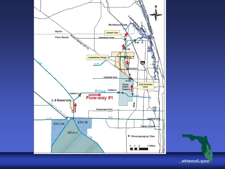
 FLOW-WAY 1 TEST PURPOSE: To test water delivery from the regional water system to the Loxahatchee River Basin using the existing infrastructure TEST DATE - July 1 – July 3, 2008
 Flow-way #1 G-160 Northlake Bridge Control #2 Pump Station G-161 M Canal Widening Grassy Waters Preserve – M Canal
 TEST CRITERIA Establish baseline stages/flow rating curves Control GWP releases to limit effect on apple snails Release ~150 cfs at Control 2, 100 cfs at G-161, 100 cfs to NWFLR Maintain appropriate stages at GWP, G-161 and G-160 Ensure coordination with stakeholders Measure water flow at critical locations Obtain water quality samples during test
 CTRL 2 7/1/08 147 G 161 41") RESULTS DATE Calculated Daily average flow (cfs) CTRL 2 7/1/08 147 G 161 41 G-160 G-92 73 110 Lainhart Dam 128 7/2/08 147 91 160 138 200 7/3/08 143 50 206 71 215
RESULTS DATE Calculated Daily average flow (cfs) CTRL 2 7/1/08 147 G 161 41 G-160 G-92 73 110 Lainhart Dam 128 7/2/08 147 91 160 138 200 7/3/08 143 50 206 71 215
 Measured Flows DATE Flow Station Ctrl 2 G-161 G-160 7/2/08 150 - 100 E. Perimeter Canal 35 7/3/08 - 95 80 -
 G-161 TW G-160 HW") Measured Avg. Daily Water Levels DATE Stage Elevation (feet NGVD) G-161 TW G-160 HW 7/1/08 GWP (G 161 HW) 18. 18 16. 14 15. 03 7/2/08 18. 04 17. 12 15. 13 7/3/08 18. 15 17. 10 14. 98
Measured Avg. Daily Water Levels DATE Stage Elevation (feet NGVD) G-161 TW G-160 HW 7/1/08 GWP (G 161 HW) 18. 18 16. 14 15. 03 7/2/08 18. 04 17. 12 15. 13 7/3/08 18. 15 17. 10 14. 98
 Conclusions Confirmed that if replacement water is available, structures can be operated to deliver flow Confirmed 150 cfs at control 2, but only 35 cfs at E. perimeter canal G-161 operated to deliver 100 cfs to C-18 Flow to NWFLR exceeded 100 cfs during test period Each structure is critical and operation must be synchronized to achieve results Measured flows agreed with estimated
 G-92 Structure Replacement
 will") G-92 Structure Proposed Design & Location Ø New in-kind (single barrel, box culvert) will be installed to maintain flood protection and conveyance Located adjacent to existing structure Ø Existing structure to be demolished Ø
G-92 Structure Proposed Design & Location Ø New in-kind (single barrel, box culvert) will be installed to maintain flood protection and conveyance Located adjacent to existing structure Ø Existing structure to be demolished Ø
 G-92 Structure Background Ø Structure supplies water from the C-18 canal to the Loxahatchee River via the South Indian River Drainage District canal C-14 Erosion and structure deterioration has limited structure capacity Ø Failure of the existing structure became critical during 2004 hurricane season Ø
 G-92 Structure Benefits of New Structure Reliability Extended service life Remote operation Public safety Flood protection Water delivery
 G-92 Structure Operation New structure will not deviate from existing operational criteria. Remote operation through telemetry
 G-92 Structure Replacement Schedule Bid opening scheduled for September 29, 2008 at 2: 30 p. m. Construction start – late November to early December 2008 Construction time frame - 300 days