

d6ea07210e0a367e0e90560fd59af4b2.ppt
- Количество слайдов: 200
 University Of Moratuwa Lecture 2012
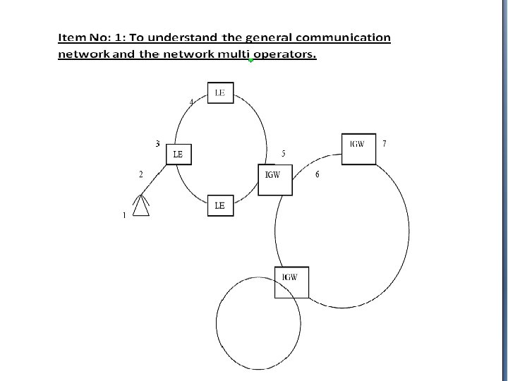
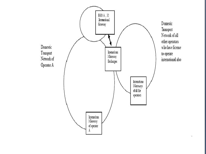
 PART 1 • TELEPHONE NET WORK
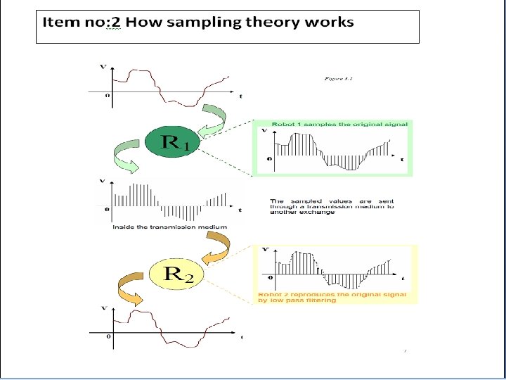
 PART 2 • PULSE CODE MODULATION
 Exercise 1: Convert the following denary numbers to binary(Don’t use the method of dividing by 2, use the finger method) • • • (a) 5 (b) 9 (c) 16 (d)33 (e) 67 (f) 120 (g) 520 (h) 1028 (i) 2050 (j) 4100 (k) 8200 (l) 16401
 5=101 (b) 9=1001 • (c) 16=10000 (d)33=100001 •") Answer to Exercise 1 • (a) 5=101 (b) 9=1001 • (c) 16=10000 (d)33=100001 • (e) 67=1000011 (f) 120=1111000 • (g) 520=1000001000 (h) 1028=10000000100 (i) 2050=10000010 (j) 4100=100000100 • (k) 8200=1000001000 (l) 16401=10000010001 • •
Answer to Exercise 1 • (a) 5=101 (b) 9=1001 • (c) 16=10000 (d)33=100001 • (e) 67=1000011 (f) 120=1111000 • (g) 520=1000001000 (h) 1028=10000000100 (i) 2050=10000010 (j) 4100=100000100 • (k) 8200=1000001000 (l) 16401=10000010001 • •
 • • (a)") Exercise 2 Convert the following from binary to Denary(Using fingers only) • • (a) 101 (b) 110 (c) 1001 (d) 11101 (e) 100000 (f) 1011010 (g) 111000111
Exercise 2 Convert the following from binary to Denary(Using fingers only) • • (a) 101 (b) 110 (c) 1001 (d) 11101 (e) 100000 (f) 1011010 (g) 111000111
 101 (b) 110 (c) 1001 (d) 11101") Answers to Exercise 2 • • (a) 101 (b) 110 (c) 1001 (d) 11101 (e) 100000 (f) 1011010 (g) 111000111 5 6 9 29 32 90 455
Answers to Exercise 2 • • (a) 101 (b) 110 (c) 1001 (d) 11101 (e) 100000 (f) 1011010 (g) 111000111 5 6 9 29 32 90 455
 Exercise 3 Convert the following denary numbers to hexa and then to binary • • (a) 9 (b) 20 (c) 36 (d) 129 (e) 518 (f) 1030 (g) 4095 (h) 8200
 9 (b) 20 (c) 36") Answers to Exercise 3 • • • Denary (a) 9 (b) 20 (c) 36 (d) 129 (e) 518 (f) 1030 (g) 4095 (h) 8200 Hexa 9 14 24 81 206 406 FFF 2008 Binary 1001 10100 1000000110 10000000110 111111 1000001000
Answers to Exercise 3 • • • Denary (a) 9 (b) 20 (c) 36 (d) 129 (e) 518 (f) 1030 (g) 4095 (h) 8200 Hexa 9 14 24 81 206 406 FFF 2008 Binary 1001 10100 1000000110 10000000110 111111 1000001000
 Convert the following samples into encoded format and calculate the signal /noise ratio • 700 m. V -400 m. V 300 m. V • 100 m. V 1515 m. V -95 m. V
 Answers • 700 m. V -400 m. V 300 m. V • 1101 01010001 11001001 175 50 ∞ • 100 m. V 1515 m. V -95 m. V 10110001 11110000 0011000 25 72 295
 Pcm equipment
 contd") Pcm equipment(2) contd
Pcm equipment(2) contd
 PART 3 • HIGHER ORDER PCM
 Multiplex Level STM 1 STM 4 STM 16 STM") Technological Evolution (Fill the blanks) Multiplex Level STM 1 STM 4 STM 16 STM 64 STM 256 Speed Period of the Pulse No: of voice channels
Technological Evolution (Fill the blanks) Multiplex Level STM 1 STM 4 STM 16 STM 64 STM 256 Speed Period of the Pulse No: of voice channels
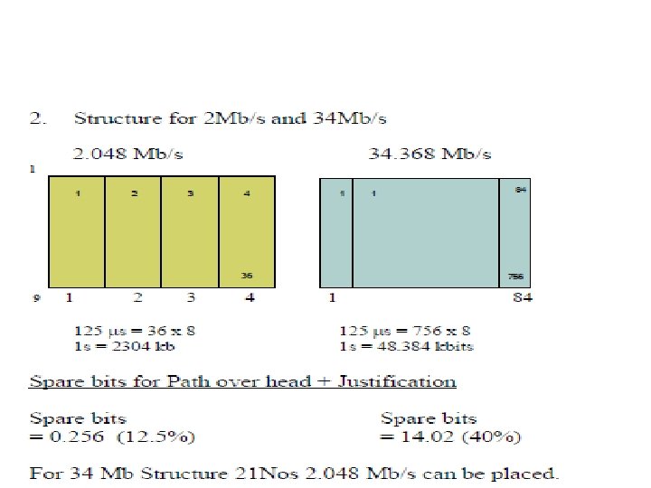
 Technological Evolution at a glance Multiplex Level Speed Period of the Pulse No: of voice channels STM 1 155. 52 Mbps 1890 STM 4 622. 08 Mbps 6. 4 ns 1. 6 ns STM 16 2. 5 Gbps 400 ps 30240 STM 64 10 Gbps 100 ps 120960 STM 256 40 Gbps 25 ps 483840 7560

 PART 4 • BASICS OF OPTICAL FIBRE
 What is Snell’s Law? • This describes the bending of light rays when it travels from one medium to another. Air Glass Air Water
 of the angles of") Snell's law states that the ratio of the sines (Sin) of the angles of incidence and refraction is equivalent to the ratio of velocities in the two media, or equivalent to the opposite ratio of the indices of refraction. Sin Ө 1 Sin Ө 2 = n 2 Sin Ө 1 n 1 Sin Ө 2 = n 2 n 1 Sin Ө 1 = n 2 Sin Ө 2 PO - Ray of Incidence medium 1 OQ - Ray of Refraction medium 2 Ө 1 - Angle of Incidence Ө 2 - Angle of Refraction n 1 - RI for n 2 - RI for
Snell's law states that the ratio of the sines (Sin) of the angles of incidence and refraction is equivalent to the ratio of velocities in the two media, or equivalent to the opposite ratio of the indices of refraction. Sin Ө 1 Sin Ө 2 = n 2 Sin Ө 1 n 1 Sin Ө 2 = n 2 n 1 Sin Ө 1 = n 2 Sin Ө 2 PO - Ray of Incidence medium 1 OQ - Ray of Refraction medium 2 Ө 1 - Angle of Incidence Ө 2 - Angle of Refraction n 1 - RI for n 2 - RI for
 TOTAL INTERNAL REFLECTION n 1 Sin Ө 1 = n 2 Sin Ө 2 With the increase of the angle of incidence, the angle of refraction increases accordingly. When reaches φ2 90°, there is no refraction and φ1 reaches a critical angle (φc ) Beyond the critical angle, light ray becomes totally internally reflected
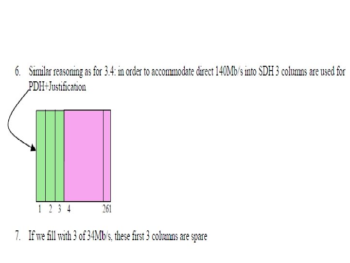
 Attenuation in Fibre optical fibre behaves differently for different wavelength of light. The following diagram shows that. The three windows of wavelengths where the attenuation is lower is given below. Hence these 3 windows are mostly used for practical purposes.
 1. General Observation on Attenuation and the Present Day Technology • Attenuation is low between 1500 nm-1700 nm in wavelength. • This gives rise to operate 24 Tbps speed • How? C=fλ where C=3*108 • And f 1 -f 2=[c/(1500 nm)]-[c/1700 nm]=24 Tbps • The present day technology goes up to 10 Gbps or 40 Gbps. • STM 1 STM 4 STM 16 STM 64…… STM 256 155. 52 Mbps 620 Mbps 2. 5 Gbps 10 Gbps 40 Gbps 6. 4 ns 1. 6 ns 400 ps 100 ps 25 ps
 SEA-ME-WE 4 Cable System Configuration Diagram
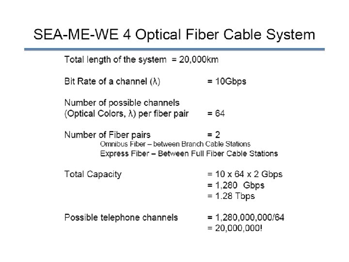
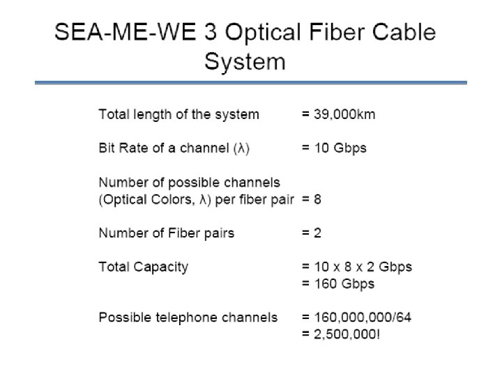
 Present day technology adapting to the optical fibre The following 2 major factors play a vital role in designing the maximum capacity of an optical fibre • How far the digital multiplexing can be achieved • As at present , 488 ns micro information of a bit pertaining to 2 Mbps PCM stream will be reduced to 25 ps when it goes through STM 64 (10 Gbps). If the technology improves to shrink less than 25 ps , then the number of bits in the higher order PCM will be more than 10 Gbps. • To transmit 10 Gbps, the optical fibre requires a bandwidth of around 0. 078 ns = 78 ps ( for 1 wavelength) • If the available bandwidth in the optical fibre is 200 ns , the number of wavelengths that can be produced is around 2400 , which will result in producing a total of 24 Tbps. • Hence both Time Division Multiplexing and Dense Wave Division Multiplexing can further improve the traffic carrying capacity of an optical fibre up to a total of 24 Tbps.
 Optical Fibre
 Optical Fibre
 Future Scenarios Theoretical Maximum of an Optical Fibre Cable 488 ns 100 ps 1 TDM 2 Mbps Transponders λ 1 2 λ 2 2399 10 Gbps λ 2399 2400 Optical Fibre Only 1 core is needed λ 2400 Number of wavelengths = ( 24 * 103 Gb ) / 10 Gb = 2400 wavelengths
 PART 5 COMMON CHANNEL SIGNALLING
 MESSAGE TYPES • BASIC MESSAGE • HOMOGENIOUS MESSAGE • NON HOMOGENEOUS MESSAGE
 Basic Message Instruction Fixed = Data K 1 Variable Message for Homogenous Network Label Instruction Data = K 2 OPC 14 bits DPC CIC 14 bits 12 bits OPC – Originating Point Cord DPC – Destination Point Cord CIC – Circuit Identification Cord
 Message for Non-Homogenous Network SIO K 2 Label National or International Message User 4 bits Instruction Data 4 bits SIO - Service Information Octel K 2 - Message for Homogenous Network Part Now we are ready with the complete message, can we transmit it just as it is? NO WHY NOT?
 IAM ACM ANC CBK
 H 1 H 0 0000 0001 IAM SAM 0010 OSM COT CCF 0011 ORQ 0100 ACM CHO 0101 SEC COC NNC ADI CFL SSB UNN 0110 ANC ANN CBK CLF RAN FOT CCL 0111 RLG BLO BLA UBL UBA CCR RSC 1000 MGB MBA MGU MUA HOA HBA HGU 1001 CFM CPA CSV CVM CHM CLI 1010 1011 0010 0011 0100 0101 0110 0111 1110 1111 1001 1010 1011 1100 ACB DPN 1101 1110 MPR 1111 Spare reserved for national use LOS SST Spare reserved for national use EUM EAM HUA GRS GRA SGB Spare reserved for international and basic national use 1100 1101 1000 SBA SGU SUA
 Basic concept of message transmission to establish a call IAM B ACM ANC A Ringing current to subscriber “B” n ringback tone to subscriber “A” Speech CBK Node X Node Y IAM H 0 H 1 0001 ACM H 0 H 1 0100 0001 H 0 H 1 0110 0011 (Initial address message) (Answer complete mesaage ) ANC CBK 20 Bits 4 Bits Dial Number Fixed (8 Bits) No Data Variable
 HOW THE COMMON CHANNEL SIGNALLING WORKS • ASSUME A CALL IS ESTABLISHED IN A NETWORK WHERE THERE ARE TWO EXCHANGES(EX X & EX Y) ARE CONNECTED WITH 16 PCM SYSTEMS. • THE CALL IS CONNECTED VIA CIRCUIT NUMBER 305. ASSUME P(0) TS 16 & P 1(1) IS USED FOR COMMON CHANNEL SIGNALLING. • DRAW HOW THE SIGNALS ARE ESTABLISHED BETWEEN THE EXCHANGES(assume the call is establised, and after the call, A keeps the receiver first) • Calculate the total times taken forward & backward signalling
 Need to transfer message between A to B P 0 f P 15 f X Y exchange P 0 b P 1 b Customer A P 15 b Customer B
 ( P") Helicopter View Exchange X IAM ( P 0 f TS 16 ) ( P 0 b TS 16 ) ACM RBT ( P 0 b TS 16 ) ( P 9 f TS 28) ( P 0 f TS 16 ) ( P 9 TS 28) ANS speaking CBR ( P 9 b TS 28)
Helicopter View Exchange X IAM ( P 0 f TS 16 ) ( P 0 b TS 16 ) ACM RBT ( P 0 b TS 16 ) ( P 9 f TS 28) ( P 0 f TS 16 ) ( P 9 TS 28) ANS speaking CBR ( P 9 b TS 28)
 Name Standards Purpose IAM Initial Address Message Dialing Information ACM Address Complete Message B customer free or not RBT Ring Back Tone herd by A ANS Answer Signal Charge B customer answer or not Call Back Tone Release the circuit CBR
 ERROR CONTROL • FORWARD ERROR CORRECTION • Detect and correct the error • In unidirectional transmission • BACKWARD ERROR CORRECTION • Detect the error and request for retransmission • In bydirectional transmission
") Understanding cyclic redundancy code of error correction (Question)
Understanding cyclic redundancy code of error correction (Question)
 CALCULATION !
 Number of voice channel for voice communication between X and Y = (31 * 14) + (30 *2) 494 Channel number that we use = 305 If we numbered voice channel from 1 to 494 : - Select related TS 30 + 30 =60 305 – 60 = 245 / 31 = 7 mod 28 7+2=9 P 9 TS 28 (PCM no = 9 , TS no = 28)
 Number that we dial = 15904607 IAM 0001 4 bits 0011 8 1000, 1010, 1001, 0000, 1100, 0000, 1110 4 4 bits 4 * 8 bits K=56 bits Message CRC 8 bits SCF SIO 1 2 305 K 16 16 8 12 12 14 56 bits bits Total bits = 150 8 bits
 ACM 0001 0110 4 bits 8 bits K=16 bits Message CRC 8 bits SCF SIO 1 2 305 K 16 bits 8 bits 12 bits 14 bits 16 bits Total bits = 110 8 bits
 ANC 0001 0110 4 bits K=8 bits Message CRC 8 bits SCF SIO 1 2 305 K 16 bits 8 bits 12 bits 14 bits 8 bits Total bits = 102 8 bits
 CBR 0001 0110 4 bits K=8 bits Message CRC 8 bits SCF SIO 1 2 305 K 16 bits 8 bits 12 bits 14 bits 8 bits Total bits = 102 8 bits
 Conclusion • time forward message = 2. 34 ms • time forward message = 4. 906 ms
 Phases of a call Dial Tone Dialing Signaling Answer Ring back Tone Speak Release
 ERROR CONTROL • FORWARD ERROR CORRECTION • Detect and correct the error • In unidirectional transmission • BACKWARD ERROR CORRECTION • Detect the error and request for retransmission • In bydirectional transmission
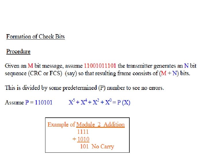
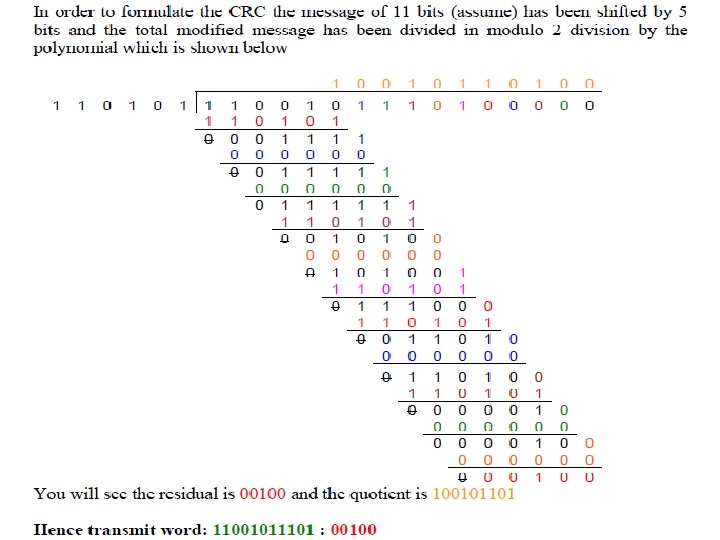
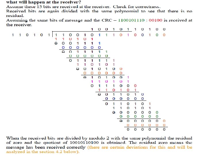
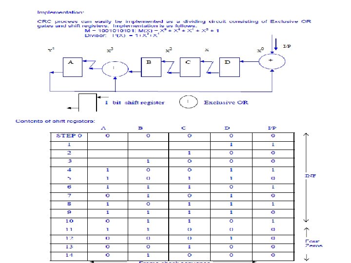
 CYCLIC REDUNCY CODE OR FRAME CHECH SEQUANCE • DESIGNED TO DETECT NOISE BURST • ACCORDING TO THE NOISE CHARACTERISTICS A POLYNOMIAL IS IDENTIFIED(N+1 BITS) • SHIFT THE MESSAGE BY N BITS • THEN DIVIDE BY MOULO 2 THE SHIFTED MESSAGE BY THE POLYNOMIAL • GET THE RESIDUAL OF N BITS & SHIFT THE MESSAGE BY THESE BITS AS CRC • AT THE RECEIVER IF THERE ARE NO ERRORS, YOU WILL NOT GET ANY RESIDUAL WHEN YOU DIVIDE THE RECIEVED MESSAGE BY THE SAME POLYNOMIAL
 EXAMPLE ON CRC


") Understanding cyclic redundancy code of error correction (Question)
Understanding cyclic redundancy code of error correction (Question)
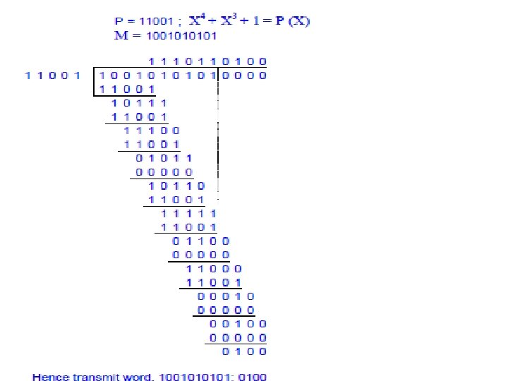
 Hence there are no errors
 Hint to answer • Write the polynomial in x • Draw the 1 bit shift registers and the circuit diagram • Write the timing equations for n+1 th step for each output • Sketh the output map– no of columns=no of outputs+steps+input(pl add to the message the no of zeros or crc depending upon the situation, no of rows has to be input+2 • Carryout the timing equation for each step, the last step will give you the output
=x 4+x 3+x 0 • X 4 X 3 X") CRC • Polynomial: P=11001, P(x)=x 4+x 3+x 0 • X 4 X 3 X 2 X 1 A + • Timing equations • • An + In = Dn+1 Dn = Cn+1 Cn = Bn+1 An + Bn = An+1 B C Input Data X 0 D + I
CRC • Polynomial: P=11001, P(x)=x 4+x 3+x 0 • X 4 X 3 X 2 X 1 A + • Timing equations • • An + In = Dn+1 Dn = Cn+1 Cn = Bn+1 An + Bn = An+1 B C Input Data X 0 D + I
 An + Bn = An+1 Step Cn = Bn+1 Cn+1= Dn+1 An + In = Dn+1 0 A 0 B 0 C 0 D 0 Input Reset 1 0 0 1 2 0 0 0 1 0 3 0 0 1 0 0 4 0 1 0 0 1 5 1 0 0 1 0 6 1 0 1 1 1 7 1 1 1 0 0 8 0 1 1 9 1 0 10 1 1 11 0 1 1 0 0 12 1 1 0 0 0 13 0 0 0 14 0 0 15 0 1 0 0 Out put
 An + Bn = An+1 Cn = Bn+1 Cn+1= Dn+1 An + In = Dn+1 Step A B C D Input 0 0 0 Reset 1 0 0 1 2 0 0 0 1 0 3 0 0 1 0 0 4 0 1 0 0 1 5 1 0 0 1 0 6 1 0 1 1 1 7 1 1 1 0 0 8 0 1 1 9 1 0 10 1 1 11 0 1 1 0 0 12 1 1 0 0 0 13 0 0 0 14 0 0 15 0 1 0 0 Out put
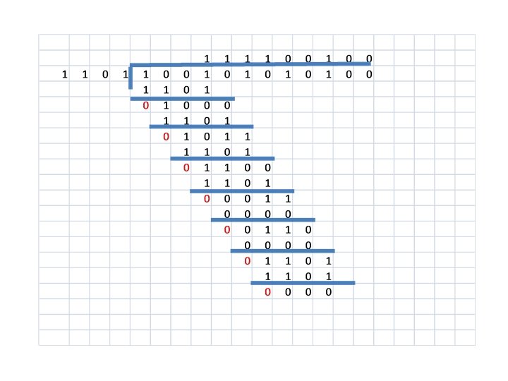
 QUESTION • SHOW THE FOLLOWING RECEIVED MESSAGE IS IN ERROR, FOR THE SAME TRASMITTED MESSAGE ie 1001010100 • Received message: 10110100010100 • WRITE THE ERROR MESSAGE EQUATION
 The remainder 00010 implies that there is an error
 ERROR EQUATION • TRANSMITTED MESSAGE + RECIEVED= ERROR MESSAGE • 1001010100 • 10110100010100 001000000 = ERROR MESSAGE E(X)=X 6 + X 11
 INSTANCES WHERE THE CRC IS FAILED TO ANSWER? • THER ARE INSTANCES WHERE THE CRC WILL FAILED TO ANSWER, ONE SUCH INSTANCES WILL BE WHEN THERE ARE ERRORS INTRODUCED EQUAL TO THE POLYNOMIAL
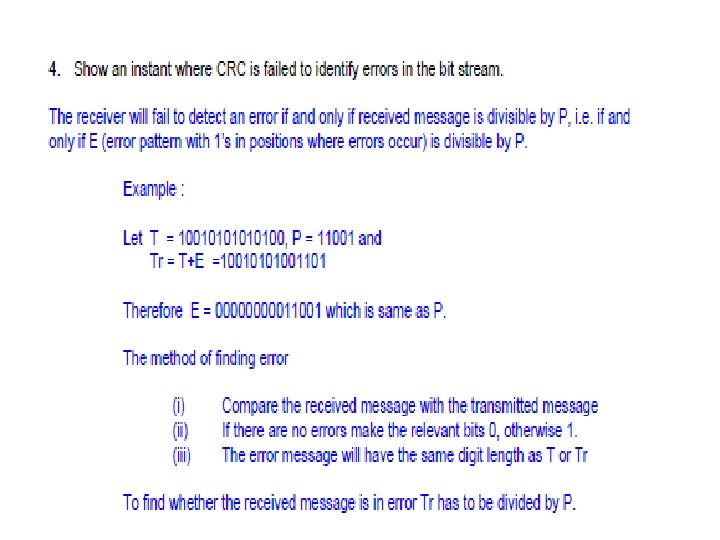
 • ASSUME THE FOLLOWING •") WHEN ERROR MESSAGE IS EQUAL TO THE POLYNOMIAL (EXAMPLE) • ASSUME THE FOLLOWING • TRANSMITTED MESSAGE • 10010100 • RECEIEVED MESSAGE • 100101001101 • POLYNOMIAL • 1101 • SHOW THAT CRC IS FAILED TO IDENTIFY THE ERROR IN THE MESSAGE?
WHEN ERROR MESSAGE IS EQUAL TO THE POLYNOMIAL (EXAMPLE) • ASSUME THE FOLLOWING • TRANSMITTED MESSAGE • 10010100 • RECEIEVED MESSAGE • 100101001101 • POLYNOMIAL • 1101 • SHOW THAT CRC IS FAILED TO IDENTIFY THE ERROR IN THE MESSAGE?
 THOUGH THE RESIDUAL IS 0 THERE IS AN ERROR IN THE RECEIEVED MESSAGE • Hint divide the received message by mod 2 • Then observe that no residuals • Write the error message & compare with the polynomial
 TRY A CRC SUM • • • TRANSMIT MESSAGE 11001011101 POLYNOMIAL 101101 FIND OUT THE CRC DRAW THE CIRCUIT DIAGRAM AND SHOW CLEARLY HOW YOU PRODUCE CRC?
 How a message is transmitted
 Preventive cycle retransmission method of error correction
 Question on basic method
 4 layers of CCITT no: 7
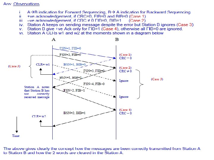
 How CCITT No: 7 works- Study about the layered structure Layer 4 Instructions DATA Layer 3 SIO Label k 1 k 2 k 1 Layer 2 W 0 SCF W 5 K 2 Layer 1 FSN=5, F IB=1 SCF Actual message Signaling Link Message Signal handline control Station A K 2 K 1 W 127 DPC=st B LABEL CONTENTS User Part Layer 4 CRC=0 SCF=Sequence control field OPC|DPC|CIC Layer 3 Layer 2 Clear W 5 BS N=5 1 IB= , B SCF Link Control Message Error detection type and correction Station B
 How reroutine is done? Layer 4 DATA Layer 3 SIO Label k 1 k 2 k 1 Layer 2 W 0 W 5 SCF K 2 Layer 1 FSN=5, F Layer 2 Layer 3 CRC=0 IB=1 SCF K 2 DPC=st C W 127 SCF=Sequence control field Station A Clear W 5 1 IB= , B N=5 BS SCF FSN 10 , BIB 0 K 1 K 2 SCF K 2 Station C K 2 W 10 Station B
 QUESTION • SHOW THE FOLLOWING RECEIVED MESSAGE IS IN ERROR, FOR THE SAME TRASMITTED MESSAGE ie 1001010100 • Received message: 10110100010100 • WRITE THE ERROR MESSAGE EQUATION
 The remainder 00010 implies that there is an error
 ERROR EQUATION • TRANSMITTED MESSAGE + RECIEVED= ERROR MESSAGE • 1001010100 • 10110100010100 001000000 = ERROR MESSAGE E(X)=X 6 + X 11

 1 2 3 4 5 6 7 8 9 10 11 12 13 14 15 16 17 0 0 0 1 0 1 1 0 0 0 0 1 1 0 1 1 1 0 0 0 0 1 1 1 0 0 0 0 0 1 1 0 0 0 0 1 1 1 0 0 0 0 1 1 1 0 0
 How a message is transmitted
 Basic method of error correction
 Preventive cycle retransmission method of error correction
 Question on basic method

 4 layers of CCITT no: 7
 Link switching networks
 3 stage link switching networks
 Part 6 • Switching network
 Basic analogue switch Output C Analogy D A B A A B B Input No of points =4 Full available Switch Non blocking switch All the voltages generated in the phone can be seen in the points C D
 4 4 switching 16 No: of * points = Is it fully available = Yes Is it non-blocking = Yes When the number of inputs and no: of ouptuts increases , we have to think about a alternative solution
 QUALITY FACTORS OF A SWITCHING NETWORK A B E F C D G H To have full availability, we should have at least 1 link from the input small switch to a small output switch as shown above Blocking: A B C D How to make this non-blocking? E F G H A B C D When A is connected to E, can B be connected to F? No, therefore this is a blocking network E F 2 2 G H
 2 stage Link switching networks full available but blocking. How to make non blocking
 2 stage Link switching networks full available and non blocking. 3 3 3 3 3
 ANALYSIS OF 3 stage link switching networks for non blocking
 ANALYSIS OF 3 stage link switching networks for non blocking 1 2 2 1
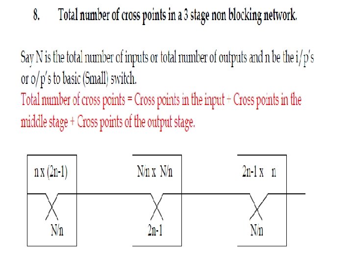
 Non-blocking 3 stage switching network
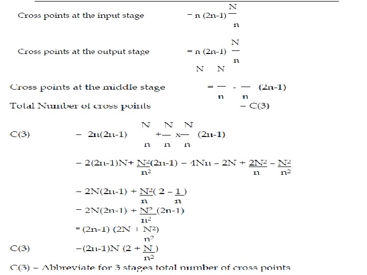
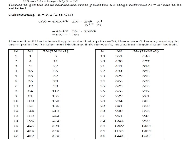
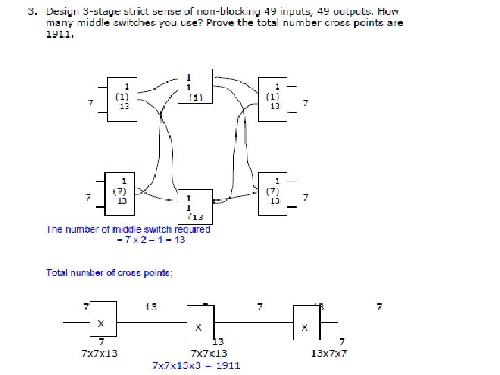
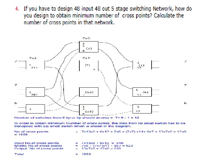
 Near minimum cross points
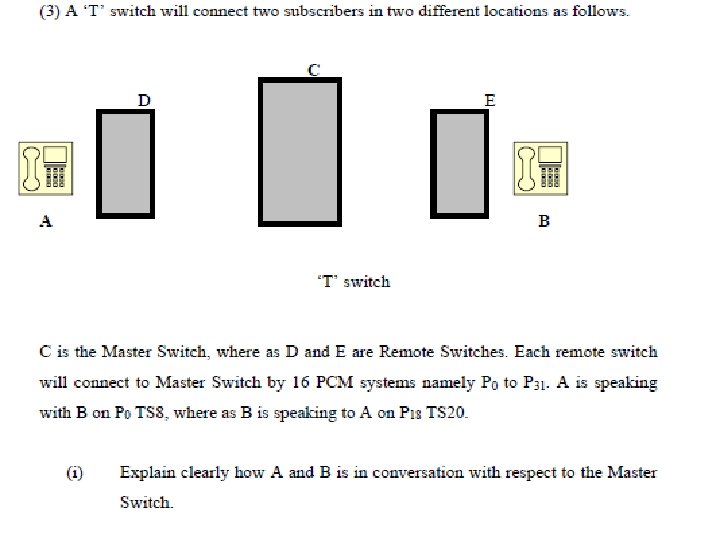
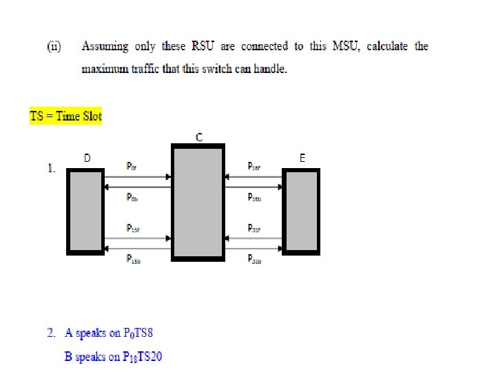
 Working of T switch Assume a master switch is connected with 2 RSU’s A B
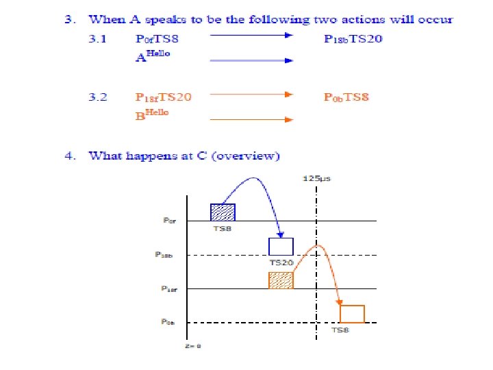
 Working of T switch Assume a master switch is connected with 2 RSU’s as shown in the figure below Assume 16 PCm systems are connetcted to from RSU to MSU B A Now assume that A is speaking with B A speaks in p 1 TS 5 and B in p 16 TS 10 What will happen at the master switch C ? Switching Equation A’s hello !! P 1 f TS 5 ------- P 16 b TS 10 B will hear. B’s hello !! P 16 f TS 10 --- P 1 b TS 5 A will hear.
 Detailed working of T-switch Timing chart A’s hello !! P 1 f TS 5 ------ P 16 b TS 10 B will hear. B’s hello !! P 16 f. TS 10 ---- P 1 b TS 5 A will hear. P 1 f TS 5 P 16 b TS 10 P 16 f TS 10 P 1 b TS 5 T=0 T=125µs
 What really happens at the T-switch A’s hello !! B’s hello !! P 1 f TS 5 ------ P 16 b TS 10 P 16 f. TS 10 ---- P 1 b TS 5 B will hear. A will hear. 4 4 2 W 0 P 1 f TS 5 1 1 P 16 f TS 10 W 5 3 W 522 2 Go to W 522 W 0 W 5 Go to W 522 3 W 1023 8 Bits Buffer Memory Microprocessor-2 actions for each channel in 125µs W 1023 10 Bits Control Memory
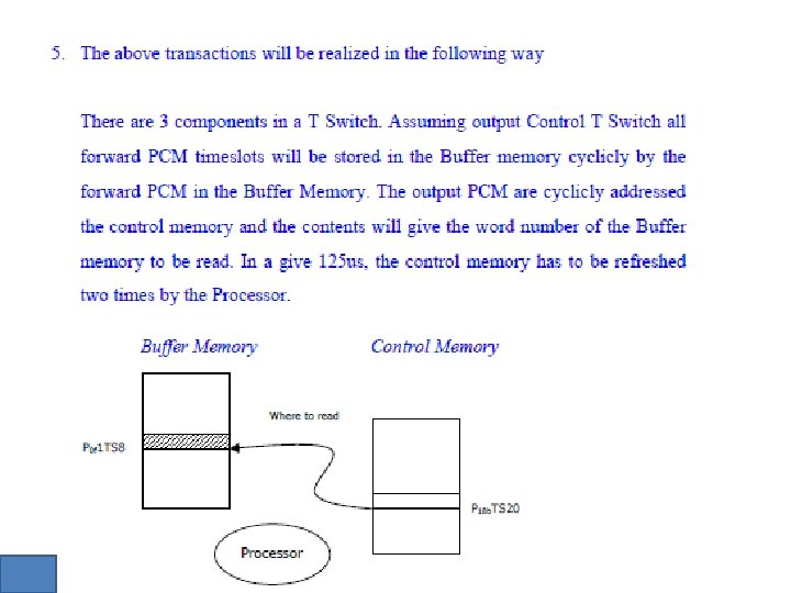
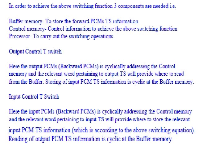
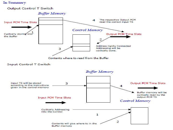
 TYPES OF T SWITCHES • WHAT WE HAHE STUDIED NOW IS OUTPUT CONTROLLED T SWITCH • THE INPUT PCM TSS ARE CYLICLY STORE IN THE BUFFER MEMORY • THE OUT PCM ARE CYCLICLY ADDRESSING THE CONTROLLED MEMORY, THE CONTENTS WILL TELL YOU WHERE TO READ AND TRANSPORT IT TO THE DESTINATION. • THE OUTPUT PCMS ARE RIGIDLY CONNECTED TO THE CONTROLED MEM, ORY THATS WHY IT IS CALLED OUT PUT CONTROLLED T SWITCH • SIMILARLY CAN YOU TRY A INPUT CONTROLLED T SWICH AND WRITE ITS CHARACTERISTICS?
 CHARACTERISTICS OF INPUT CONTROLLED T SWITCH • INPUT PCMS ARE RIGIDLY CONNECTED TO THE CONNTROLLED MEMORY • THE INPUT PCMS ARE CYCLICLY ADDRESSING THE CONTROLLED MEMORY. THE CONTENTS WILL TELL YOU WHER TO STORE IN THE BUFFER MEMORY. • THE OUTPUT PCMS ARE CYCLICLY READING THE BUFFER MEMORY.
 BASIC COMPONANTS OF A SWITCHING SYSTEM • • SWITCHING UNIT CONTROLLED UNIT PERIPARALS SOFTWARE • IS IT ANALOGUES TO HUMAN BODY? • YES, EXCEPT FREE WILL OF THE HUMAN, THIS SYSTEM WILL HAVE HEART, BRAIN & MIND
 Comparison of Human with Animal & SWITCHING NODE HUMAN HEART BRAIN MIND TRUTH FREE WILL/GOOD TELEPHOE NODE SWITCHING NETWORK CONTROL NETWORK SOFTWARE PROGRAMMING ANIMAL HEART BRAIN INSTINC
 SWITCHING UNIT • MAIN FUNCTION—connecting to an input to a output • In the case of local node, input will be the customer, and the output will be a route, where the call is destined to • Limiting factor: no of connections that can be established simultaneously is the limiting factor • MEASURED IN ERLANG • Present day technology : analogue & digital switches are now obsolete, now packet switching routers are deployed.
 CONTROLLED UNIT • FUNCTION: ALL THE MANAGEMENT FUNCTIONS THAT NEED TO CARRYOUT IN ESTABLISHING ACONNECTION WILL BE DONE BY THE CONTROLLED UNIT. • THE MANAGEMENT FUNCTIONS ARE /CALL ESTABLISHMENT, SENDING INFORMATION TO THE OTHER NODES, CALL BILLING FUNCTION, CUSTOMER FACCILITY MANAGEMENT ETC. . . • LIMITATION WILL BE THE OCCUPANCY OF THE PROCESSOR. NORMALLY MORE THAN 80% WILL NOT BE ADVISABLE FOR ANY PROCESSOR. ANOTHER MEASUREMENT WILL BE TLME TAKEN TO ESTABLISH A CONNECTION • TECHNOLOGY: CENTRALISED CONTROL FUNCTION HAS BEEN SHIFTED TO DITRIBUTED PROCESSER FUNCTION. MODERN NGN SWITCH WILL HAVE MOST OF THE MANAGEMENT FUNTIONS CENTRALISED TO THE CONTROL PART OF SOFT SWITCH, WHILE ROUTING PART IS DISTRIBUTED TO THE ROUTERS. ANOLGUE CONTROL(WIRED LGIC), IS OBSELETE.
 PERIPARALS • THEY ARE THE ANCILIARY EQUIPMENT TO CARRY OUT THE MAJOR FUNTIONALITIES OF THE SYSTEM. THEY BARE REGISTERS, TONE GENERETORS, TIMING DEVICES, ETC. . .
 SOFTWARE • SOFTWARE WILL PROVIDE ALL DETAILED ACTION PLANS IS BECOMING HIGLY COMPLEX. • MODULAR KIND OF SOFTWARE IS NOW ENCOURAGED. • WITH NGN TECHNOLOGY THE SOFTWARE HAS BECOME A VITAL ELEMENT FOR THE PROPER FUNCTIONING OF MUTIPLE SERVICE FACILIETIES.
 Understanding traffic concepts
 v
v
 Packet Switching
 THE IP WORLD • TODAY WE ARE IN THE IP WORLD • ALL THE NETWORKS • TDM & ATM NETWORKS ARE PUSHING TO THE IP ARE REPLACED BY IP APPLICATIONS • MODERN CODING METHODS PUSH IP NETWORKS TO GO FOR • LETS STUDY THE PACKET CONCEPTS REAL TIME APPLICATIONS
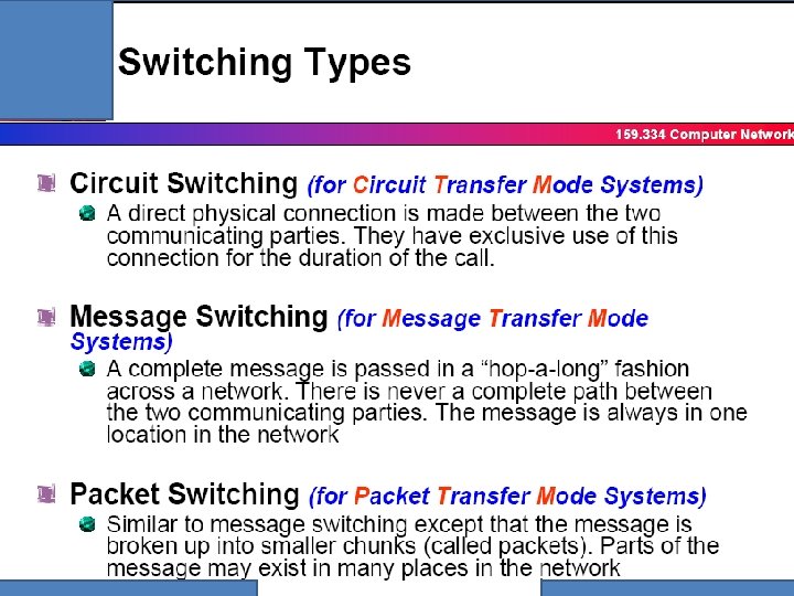
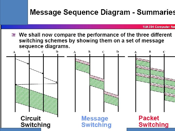
 Major switching types Circuit , Message and Packet switching
 CHRACTERISTICS OF SIGNALLING & VOICE • CHANNEL ASSOCIATED SIGNALLING & VOICE IN ONE TUNNEL-WASTAGE IN SIGNALLING, AND LESS THAN 50% EFFICIENT IN VOICE MEDIA DUE TO THE CHARACTERISTICS OF VOICE. COMMON CHANNEL SIGNALLING IS COMMONLY USED FOR MANY VOICE CHANNELS, HENCE SIGNALLING CHANNEL IS EFFICIENT. VOIE CHANNELS CARRIES THE SAME INEFFICIENCY AS IN THE CASE OF CHANNEL ASSOCIATED SIGNALLING HENCE THE CONCEPTS OF MESSAGE AND PACKET SWITCHING NETWORK TO BE CONSIDERED.

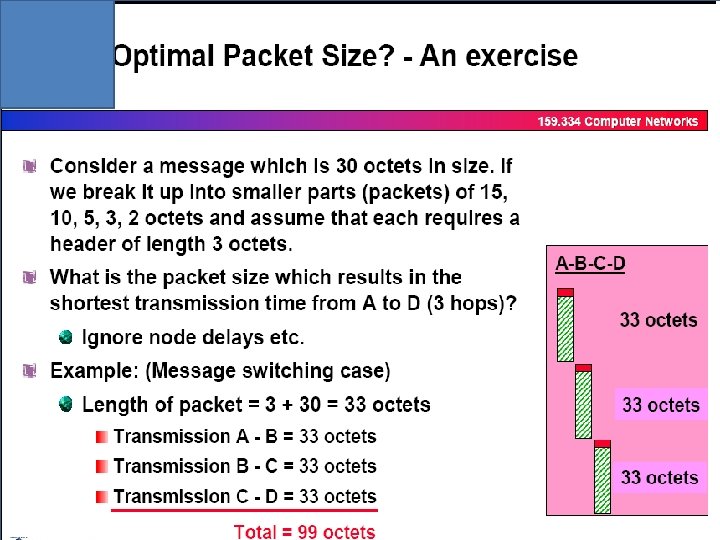
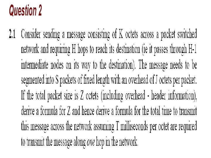
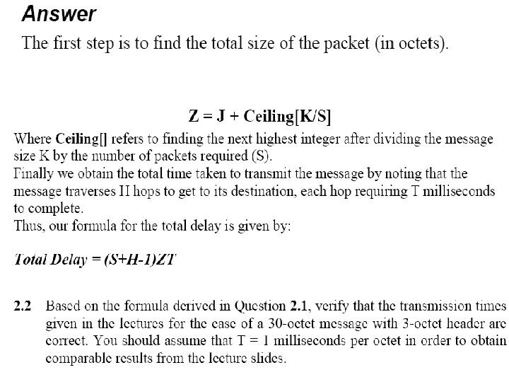
 DELAY ANALYSIS OF A MESSAGE SWITCH • TAKE THE PREVIOUS EXAMPLE, THE FOLLOWING ARE KNOWN • MESSAGE SIZE=30, OVERHEAD=3, NO OF HOPS=3, THE DELAY FOR ONE HOP/OCTET=1 MSEC. • THE TOTAL DELAY FOR 3 HOPS=33*3 MSEC • TOTAL DELAY=NO OF HOPS*NO OF OCTET IN MESSAGE+NO OF OVERHEAD OCTETS IN THE MESSAGE(THIS RESULT IS TALLYING)
 Deciding Optimum Packet Size Packet 1 l MESSAGE Packet 2 Packet 3 l l . • Shown above is a message • The message will be divided in to equal length packets • Each Packet will have a Header The header will consist the following details: – Originating Point Code – Terminating Point Code – Packet Number Packet 1
 A B C D Packet 1 Packet 2 Packet 3 Packet 2 T 1 Packet 3 Packet 1 Packet 2 Time Slots How Many Transactio ns? T 2 1 T 3 2 3 Packet 3 T 4 2 T 5 TOTAL DELAY α S + H - 1 Where S - Number of Packets H - Number of Hops 1 Therefore in this case the total delay time is α 3 + 3 – 1 = 5
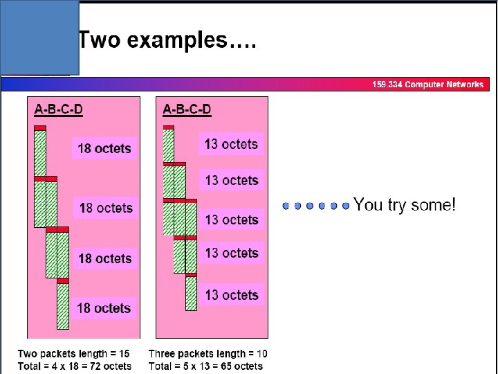
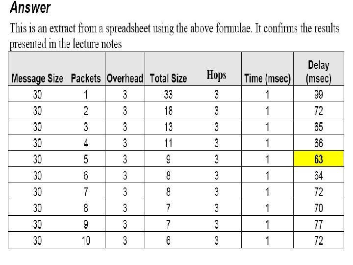
 DELAY ANALYSIS FOR PACKET SWITCHING NETWORK • TAKE TWO EXAMPLES THE 30 OCTET MESSAGE IS (1) MADE TO TWO PACKETS OF 15 OCTET EACH, (2) MADE TO 3 PACKETS OF 10 OCTETS EACH • YOU WILL OBSERVE THE FOLLOWING OVERLAP SENDING OF PACKETS, FOR EXAMPLE, WHEN 1 ST PACKET RCEIVED AT B, THIS PACKET IS SEND FROM B TO C, DURING THIS TIME THE 2 ND PACKET IS SEND FROM A TO B. NOTE THAT IN AGIVEN TIME 2 ACTIONS HAVE BEEN MADE THE TOTAL DELAY EXPERIENCED IN (1)72 MSEC (2) 65 MSEC
 Message vs Packet delay • It is easy to calculate message delay rather than packet delay , why ? • When sending packets from one node to another the following process can be adopted as against message transmission • (a)Packets can be sent to another node through different paths simultaneously • (b)Packetizing at the node and sending packets over the hop can be made in different times to maximize the sending of packets over a hop. • (C)Hence , overlap sending & receiving of packets can be achieved in a node. Hence the delay introduced in packet mode is rather complicated (than message) although it is efficient.
 hops is rather simple") Contd…. • In message mode the delay introduced in (H-1) hops is rather simple and is equal to • Message delay = K * (H-1) • In packet mode the delay is proportional to addition delay to message length and it is assumed to be • D = K*(H-1) + term proportional to message length • Delay={ S+ (H-1) } * ZT
Contd…. • In message mode the delay introduced in (H-1) hops is rather simple and is equal to • Message delay = K * (H-1) • In packet mode the delay is proportional to addition delay to message length and it is assumed to be • D = K*(H-1) + term proportional to message length • Delay={ S+ (H-1) } * ZT
 Summary
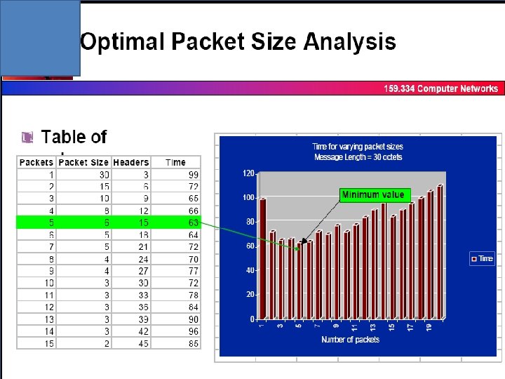
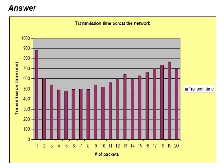
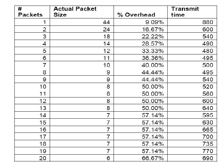
 Calculation of the optimum packet size • Deciding the optimum packet size will depend upon 2 factors • Overall delay • Overall overhead bits compared to the message • Calculate the optimum packet size of 30 octet message, where the overhead for aq packet is 3 octet?
 What is the packet network? • A packet is a unit of data that is transmitted across a packet -switched network. • A packet-switched network is an interconnected set of networks that are joined by routers or switching routers.
 Example • Packet Switching technology TCP/IP • largest packet-switched network Internet
 Why ? • Data traffic is bursty – Logging in to remote machines – Exchanging e-mail messages • Don’t want to waste reserved bandwidth – No traffic exchanged during idle periods • Better to allow multiplexing – Different transfers share access to same links
 Goals • To optimize utilization of available link capacity • To increase the robustness of communication
 Concept • A method of transmitting messages through a communication network, in which long messages are subdivided into short packets. • The packets are then sent through the network to the destination node.
 Packet-Switching Techniques Datagram Each packet contains addressing information and is routed separately Virtual Circuits A logical connection is established before any packets are sent; packets follow the same route.
 Datagram • • • Each packet treated independently Packets can take any practical route Packets may arrive out of order Packets may go missing Up to receiver to re-order packets and recover from missing packets
 Computer A 1 2 3 Need to transmit ‘ 123’ from computer A to computer B First data is broken to small pieces (PACKETS) Computer B
 Computer A 3 1 2 Packets contain header information that includes a destination address. Routers in the network read this address and forward packets along the most appropriate path to that destination. Computer B
 Computer A 2 1 3 Computer B
 Computer A 2 1 3 Computer B
 Computer A 2 1 3 Computer B
 Virtual Circuits v Datagram • Virtual circuits – Network can provide sequencing and error control – Packets are forwarded more quickly • No routing decisions to make – Less reliable • Loss of a node loses all circuits through that node • Datagram – No call setup phase • Better if few packets – More flexible • Routing can be used to avoid congested parts of the network
 Advantages • Line efficiency – Single node to node link can be shared by many packets over time – Packets queued and transmitted as fast as possible • Data rate conversion – Each station connects to the local node at its own speed – Nodes buffer data if required to equalize rates • Packets are accepted even when network is busy – Delivery may slow down • Priorities can be used
 Each") Difference between channel associated common channel and packet signaling networks Channel associated signalling(CAS) Each voice channel will have a supervisory channel(either direct or associate). Highly inefficient for the signalling channel and less than 50% efficient for the voice channel. Common Channel signalling – All supervisory Signals of voice channels are in one time slot And the voice channels have similar inefficiency as CAS Voice channel Supervisor signal Signalling and voice are going on packets whenever it is needed Packet network=Signalling and voice are sent in packets , highly efficient for voice as well as signalling. The deficiecy experienced for voice channels, in CAS & CCS has overcom
Difference between channel associated common channel and packet signaling networks Channel associated signalling(CAS) Each voice channel will have a supervisory channel(either direct or associate). Highly inefficient for the signalling channel and less than 50% efficient for the voice channel. Common Channel signalling – All supervisory Signals of voice channels are in one time slot And the voice channels have similar inefficiency as CAS Voice channel Supervisor signal Signalling and voice are going on packets whenever it is needed Packet network=Signalling and voice are sent in packets , highly efficient for voice as well as signalling. The deficiecy experienced for voice channels, in CAS & CCS has overcom