1068a7e2afdda5d25b29ee15a50721ba.ppt
- Количество слайдов: 32


UBC has built time domain electronics consisting of: A Clock Card: communications Readout cards: handle 8 columns Bias Cards: Set SQ bias and Feedback (except SQ 1_FB). Address Card-Row select for up to 41 rows. Power consumption: 120 W for 1300 bolometers.

The 145 GHz array and the Atacama Cosmology Telescope Mark Halpern University of British Columbia Photo by Michele Limon

The SCUBA 2 Cryostat and one sub-array. Eight boxes of readout electronics mat to this side of the cryostat.

The TES Focal Plane for BICEP 2 TES Antenna coupled Focal Plane Array 512 detectors (256 per polarization) 150 GHz READOUT Squid-Mux and Nyquist chips (NIST) Multi Channel Electronics (UBC)

Let’s just start with a simplified picture of what signals we would be reading out.

A very simple readout system: Squids provide sensitive, very fast current amplification. Many bolometers can be read out with one squid, either one after the other (Time Domain Multiplexing) or by running the detectors at separate AC frequencies (Frequency Domain)

Time-Domain Multiplexing: Leave the detectors running, and turn on only one 1 st stage squid at a time. A single Squid-2 can read 40 bolometers. (Depends on L/R. ) NIST makes these TD Multiplexors.

The voltage across a squid is periodic in the applied flux. Operate where gain is high

We apply a “feedback” flux at each squid to keep it operating at the peak slope of its V- curve.

Simplified time-domain multiplexing: All the first stage squids in a given row are biased on at one time. Signals are read out in columns.

The address card asserts a new row selection at 850 k. Hz. Coincident with each row select the Readout Card applies a feedback signal calculated from previous readings. The AD converters run continuously at 50 MHz. About 20 samples after each row select are discarded to allow the feedback and address signals to settle. The next ~40 samples are added together to for a single reading. This reading is the input to a feedback PID loop for each pixel. Individual pixels are visited at 850/41 ~ 20 k. Hz. Mark Halpern, UBC Physics and Astronomy

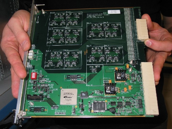
Each box of electronics contains: One Clock Card--Receives commands, packages the data, can reprogram other cards One Address card--Selects row 0 to 40 of the multiplexor. ( The pixels in row 40 are “dark”. ) Four Readout Cards-- Each reads eight columns, calculates and applies feedback signals, collects and filters data for an 8 x 41 segment of the array. Three Bias Cards--Control squids in amplifier chain. One Power Supply card Boxes bolt directly to the cryostat wall. Mark Halpern, UBC Physics and Astronomy

Mark Halpern, UBC Physics and Astronomy Filtered electrical connectors are mated to the cryostat by shafts from the front panel after the electronics are mounted on the cryostat.

Here are some data collected at 50 MHz. We do have power supply noise, which disappears when we use linear supplies.
 environment. 30 million")
The electronics work well exposed to Cosmic rays of near-space (balloon) environment. 30 million 32 bit data points read at Triumf had two candidate bit flips. This is the work of Nora Boyd. One set of electronics was exposed to a neutron fluence corresponding to a 30 day flight. There were no commanding or data retrieval errors.

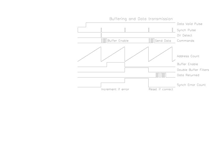
The feedback signal is filtered on the readout card. We collect full array images and apply feedback at 20 KHz, which is necessary to keep the TES system stable, but we only read out useful optical signals at 200 Hz. The Readout Cards run an infinite impulse response filter on the feedback voltages to produce an output image. This output image is always available, and is clocked out upon request, typically 200 Hz. The maximum data rate, set by the optical fibre bandwidth, is 4. 7 k. Hz for a 41 x 32 array, assuming 32 bit data words for each pixel. Mark Halpern, UBC Physics and Astronomy

Firmware has turned out to be the largest task in making this electronics work. There are five FPGA programmers at UBC, and several at the ATC. We anticipate supporting electronics and firmware through the life of SCUBA 2 and ACT.

Multichannel Readout Electronics Bolometer Readout electronics for SCUBA 2 and for ACT are being built at UBC. They are based on the NIST electronics, but are a bit more automated and have much cleaner electrical connections. Aside from the cryostat, the only electrical connection to the electronics is a 24 volt supply. Each 41 x 32 channel portion of a bolometer array is coupled its own box of electronics which is in turn connected to a data acquisition PC via optical fibre. A separate fibre synchronizes 25 MHz clocks within each box and also synchronizes data acquisition. Mark Halpern, UBC Physics and Astronomy

A single-board computer and a fibre communications card to control the MCE and a hard drive to store the data can all fit in a lunchbox.

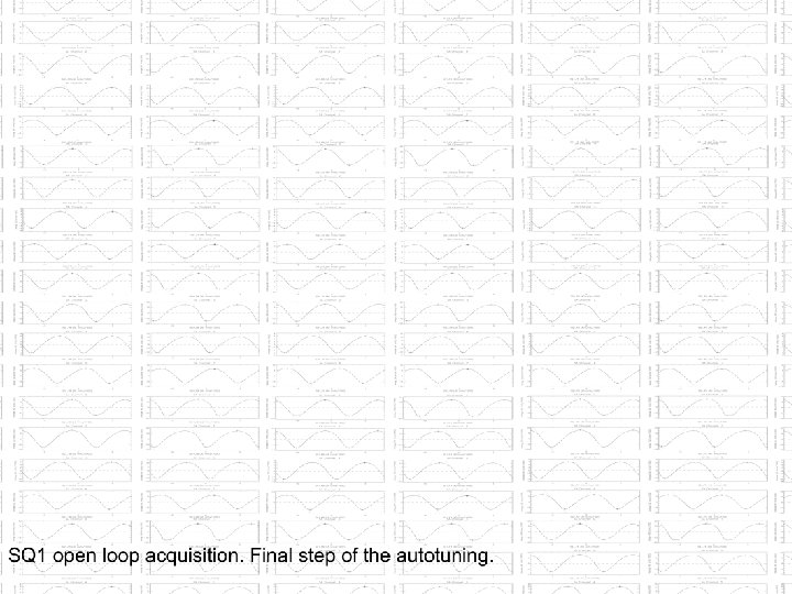
Autotuning: Sweep SQ 2 Phi while servoing SSAM Feedback to keep output constant. Repeat at several SQ 2_bias if desired.

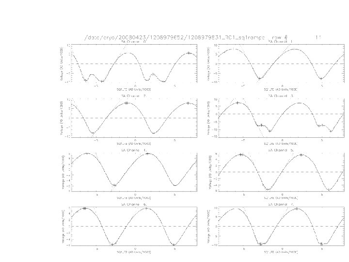
. . then repeat the process for SQ 1, adjusting SQ 2_FB. This lets you choose a value of SQ 2_FB corresponding to ideal SQ 1 slope.

First stage squid feedback is calculated at the data rate. Here is a time series once through a column with SQ 1_FB=0.

. . . and here is a similar 50 s of data with a separate PID loop running for each bolometer element.

Superconducting branch Normal branch Superconducting transition Measured remotely from UBC, 3000 miles away from the cryostat IV curse for ACT TES. 32 X 32 of these curves are acquired after each autotuning

Load curves • Also plot as power in detector vs voltage • Power constant in superconducting transition • Power proportional to V 2 in normal state • Responsivity (S) in transition proportional to 1/V Decreasing heater power

Optical response of five bolometers: Feedback Error signal This is 10 k. Hz readout of a sub-p. W optical signal. SCUBA 2 data will be filtered to 100 Hz in the electronics. (Data collected at UBC on a cryostat in New Jersey. by Elia Batastelli. )

The ACT 145 GHz array, fully assembled. Photo: Mike Neimack
1068a7e2afdda5d25b29ee15a50721ba.ppt