Turbo Cummins 2010 Presentation.ppt
- Количество слайдов: 143


Turbocharger Training Russia 2010 Rajesh Sendil – Area Sales Manager UK, Ireland, Russia and Eastern Europe

Agenda § § § § § Introduction to Cummins Inc. Cummins Turbo Technologies Overview Products and Technology 2010 Business update Aftermarket Support Examples of Current applications Turbochargers Failure Diagnosis Copy Turbochargers § Technology

Introduction to Cummins Inc

Our Vision/Mission: VISION Making people’s lives better by unleashing the Power of Cummins. MISSION Motivating people to act like owners working together. Exceeding customers’ expectations by always being the first to market with the best products. Partnering with our customers to make sure they succeed. Demanding that everything we do leads to a cleaner, healthier, safer environment. Creating wealth for all stakeholders.

The New Cummins: Global presence Less cyclical More diversified Low-cost producer Complementary businesses working together Becoming the first choice of our customers

Cummins Inc Tim Solso Tom Linebarger Jean Blackwell Bruce Carver Steve Chapman Jill Cook Thad Ewald Ignacio Garcia Mark Gerstle Marya Rose Floyd Rutan John Wall Pat Ward POWER GENERATION Tony Satterthwaite Chairman and CEO President and Chief Operating Officer Executive Vice President – Corporate Responsibility and CEO – Cummins Foundation Chief Information Officer Group Vice President – China and Russia Chief Human Resource Officer Vice President – Corporate Strategy and Business Development Chief Manufacturing and Procurement Officer Chief Administrative Officer General Counsel and Corporate Secretary Executive Director – Cummins Business Services Chief Technical Officer Chief Financial Officer DISTRIBUTION BUSINESS Pamela Carter ENGINE BUSINESS Rich Freeland COMPONENTS GROUP Anant Talaulicar

Introduction to Cummins Turbo Technologies

Overview Cummins Turbo Technologies is an autonomous Business Unit of Cummins Inc We are the leading designer and manufacturer of turbochargers for diesel and gas-derivative engines above 2. 3 litres We have over 2000 employees globally Headquartered in the UK with global manufacturing facilities in; Brazil, China, Europe, India and USA along with dedicated technical centres in UK and China

Global Customers:

Business Strategy Be the first choice for customers through our market leading dependable technology and innovative air handling solutions To profitably grow the business by delivering the best value turbocharger technology to our customers Focus on customer support excellence to achieve customer loyalty through the reliable supply of turbochargers Harnessing the skills and creativity of our employees to be the benchmark supplier of turbocharger technologies

Products & Technology

Market Drivers: § The commercial turbocharger market has seen steady growth over the past few years. This is expected to continue into the next decade and beyond § Growth is driven by increasingly stringent government emissions legislation worldwide § Turbocharging technology is seen as a key tool in enabling engine manufacturers to meet these strict criteria

Business Strategy: To profitably grow the business by delivering the best value turbocharger technology to our customers. Focus on customer support excellence to achieve customer loyalty § Reliable supply of turbochargers to all customers § Easy to do business with Provide a financial return to ensure future technology investment and growth.

Emission Regulations On-highway, heavy duty emissions legislation by country and date of introduction Date of Introduction NOx g/k. W. h PM g/k. W. h Australia Brazil China (whole) EU India (whole) Japan Korea Russia USA Euro 2 7. 00 0. 250 2005 1996 2005 Euro 3 5. 00 0. 100 2002 2004 2008 2000 2010 2005 2008 Euro 4 3. 50 0. 020 2006 2009 2010 2005 2015 2008 2010 Euro 5 2. 00 0. 020 2012 2008 2011 2015 Euro 6 0. 4 0. 01 US 04* 2. 70 0. 130 2004 US 07* 0. 27 0. 013 2007 US 10* 0. 27 0. 013 2010 Japan 05 0. 25 0. 015 2005 2014 2015 *US limits converted from g/hp. hr to g/k. W. h for comparison. US 07 legislation requires that 50% of engines a manufacturer produces should meet the US 10 NOx requirements

Product Focus Cummins Turbo Technologies has developed advanced turbocharging technologies to enable engine manufacturers to meet strict emissions criteria and engine performance requirements Can offer a portfolio of technology to meet our strategic customers’ target markets: § Holset VGT™ with electric actuation § Turbo compound System § Serial 2 Stage § M Squared™

Product Range

Holset HE Range A new technology platform for future emissions engines: Holset VGT with electric & pneumatic actuation options High pressure ratio compressors including Titanium option High durability Advanced control capability Speed & inlet air temperature measurement Fully modulating control valves (DCon) with remote intelligence option (ICon) Low flow turbine stages with wastegate for EGR engines Enhanced MWE for improved compressor map width

Holset Product Features Cummins Turbo Technologies use a number of different methods and materials to create its impellers. Each give different durability vs cost benefits: Cast Aluminium: § Standard technology § Very cost effective and suitable for mid-range turbochargers § Not suitable for those with high duty cycles Cast Titanium: § Can withstand high temperatures § Effective metal to use in heavy duty turbochargers § Titanium is a cost premium
 Aluminium: § Casting process can create defects")
Holset Product Features Machined from solid (MFS) Aluminium: § Casting process can create defects that become weaknesses in the metal § The MFS process reduces such defects considerably § Cost effective solution over Cast Ti for increasing durability MFS Titanium: § Reduces the possibility of defects seen with casting process § Process is slow and expensive § Suitable for heavy duty turbochargers with high duty cycles Semi Solid Mould (SSM) Aluminium: § Process shapes the wheels at high temperatures and cooled to set § Fewer defects than casting process § A cost effective alternative to using MFS

2010 Business Update

Global Turbocharged Engine Market § First fit volumes

A Global Presence Huddersfield Technical Centre Manufacturing Aftermarket Amersfoort Aftermarket Columbus Customer Support Technical Centre Memphis Aftermarket Charleston (Leeds Ave) Manufacturing Charleston (Palmetto) Manufacturing Sao Paulo Manufacturing Aftermarket Wuxi Manufacturing Technical Centre Aftermarket Dewas Manufacturing Pithampur Manufacturing Pune Technical Centre Customer Support Rudrapur Assembly

Global Capacity Charleston 1052 k Huddersfield 574 k Dewas 490 k Pithampur 48 k Sao Paulo 120 k Wuxi 929 k

Turbo Technologies Worldwide Sales & Volume History
 § Commercial Diesel")
Market Shares (2009) § Commercial Diesel

Aftermarket Support

Aftermarket & Distribution Network Focused on serving OEM global service networks § Specialised service, packaging & logistics Dedicated facilities: § USA, China, Europe, India and Brazil 24 hour, 7 day per week coverage § Extended opening hours § Multi-lingual Staff OEM Remanufacturing Service Independent channel of distributors § Local expertise, coverage of old, ex-OE production product, capable of specialised logistics service

Service/Spare Parts Focused on serving OEM global service networks § Specialised service, packaging & logistics Dedicated facilities: § USA, China, Europe, India and Brazil 24 hour, 7 day per week coverage § Extended opening hours § Internet Ordering § Multi-lingual Staff OEM Remanufacturing Service Independent channel of distributors § Local expertise, coverage of old, ex-OE production product, capable of specialised logistics service

UK Operations Name: Cummins Turbo Technologies Ltd. Established: In 1952 Location: Headquartered in Huddersfield, UK Product Range: Light Duty, Mid Range, Heavy Duty, High Horse Power Aftermarket, UK 200, 300, 400, 500, 600 and 800 series Capacity: 574 k Activities: Customer Account Teams, Manufacturing Technical Centre Aftermarket Other Facts: Cummins took ownership in 1973 Technical Centre, UK

India Operations Name: Cummins Turbo Technologies Ltd. Established: In 1994 as a JV with Tata Group of Companies. Became a Cummins whollyowned foreign entity in April 2007 Location: Dewas, Pithampur and Pune, India Product Range: Light Duty and Mid Range 200 and 300 series Capacity: 538 k Activities: Dewas: Customer Account Teams, Manufacturing & Aftermarket Pune: Customer Account Teams, Global Support Dewas, India

USA Operations Name: Cummins Turbo Technologies Established: 1991 Location: Leeds Ave & Palmetto, Charleston, South Carolina Columbus, Indiana Memphis, Tennessee Product Range: Mid Range and Heavy Duty Leeds Avenue, USA 300 and 500 series Capacity: 1052 k Activities: Charleston: Manufacturing Columbus: Customer Account Teams, Memphis: Aftermarket Other Facts: In July 2006, opened new purpose built second facility in Charleston; Palmetto, USA

China Operations Name: Wuxi Cummins Turbo Technologies Established: 1996 Location: Wuxi, China Product Range: Light Duty, Mid Range and Heavy Duty Capacity: 929 k Activities: Customer Account Teams 200, 300, 400 and 500 series Technical Centre Manufacturing Aftermarket Other Facts: 45: 55 JV between Wuxi Power and Cummins Turbo Technologies Wuxi, China
, Brazil Product")
Brazil Operations Name: Cummins Turbo Technologies. Established: 1987 Location: Guarulhos (Sao Paulo), Brazil Product Range: Mid Range 300 and 400 series Capacity: 120 k Activities: Customer Account Teams Manufacturing Aftermarket Sao Paulo, Brazil

Holland Operations Name: Cummins Turbo Technologies B. V. Established: 1976 Amersfoort, The Netherlands Location: Amersfoort, The Netherlands Activities: Aftermarket Distribution Centre Other Facts Cummins Turbo Technologies acquired the business, formerly Turbo Europa in 1993

Examples of Current Applications

Peterbilt with Paccar MX engine and Cummins ISX 15 – US 10 500 series Holset VGT with electric actuation on Paccar MX 400 series Holset VGT with electric actuation on Cummins ISX 15

Scania Euro IV Turbo Compound Engine Holset 500 series fixed geometry turbocharger and Holset 700 series power turbine

Volvo New HDEP Engine Platform – Euro IV Holset 500 series fixed geometry

Axial Power Turbine – Euro VI/EPA 10 Holset 500 series fixed geometry turbocharger with a Holset 800 series axial power turbine

Ford F 250 Pick-up Holset HE 221 W

Chrysler Dodge Ram 07 – EPA 07 Holset HE 351 Ve

Iveco Cursor Engines for Stralis – Euro IV Holset HE 431 V – Cursor 8 Holset HE 531 V – Cursor 10 Holset HE 551 V – Cursor 13

Daewoo CNG City Bus – Euro III Holset HX 50 G

Pisten Bully 400 Holset 400 series wastegate

Griffon Military Hovercraft 4 x Holset 500 series wastegate

Turbochargers Explained

Advantages of Turbochargers In turbochargers the exhaust gas energy which would normally be wasted is used to drive a turbine, which in turn drives a compressor to deliver compressed air to the engine. The advantages of a turbocharged engine are: § lower fuel consumption § lower emissions § better torque characteristics § lower weight and smaller engine package § lower engine noise

More Power Required Choice is either; Increase the size of engine or fit a turbocharger. 4 cyl 4 litre 80 HP 247 kg 6 cyl 6 litre 120 HP 344 kg Turbocharged 4 cyl 4 litre 122 HP 286 kg

Major Components of a Turbocharger Compressor Cover Compressor Wheel Bearing Housing Turbine Wheel Turbine Housing

How a Turbocharger Works The Turbine End The Compressor End The Oil Supply

How a Turbocharger Works The turbine housing is bolted to the exhaust manifold of the engine. The waste exhaust gasses are used to rotate the turbine wheel which is housed in the turbine casing. Turbine temperatures up to 760 deg C The turbine wheel is connected to a common shaft which in turn rotates a compressor wheel.

How a Turbocharger Works As more gas passed through the turbine housing, the faster the turbine wheel rotates. As the turbine wheel increases in speed, so does the compressor wheel. This creates a sucking process and pulls air into the compressor cover from the atmosphere (filtered). The faster the wheels spin the, the more air is sucked in.

How a Turbocharger Works As the air is sucked into the compressor cover, it is forced through a diffuser area. This compresses the air and forces it into the engine This process causes the air to increase in temperature, up to 200 degrees C
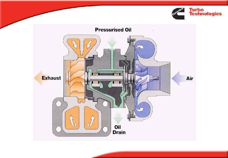

Typical Turbocharger components Oil inlet Impeller Wheel Bearing Housing Wastegated turbine housing Turbine wheel Compressor Housing Wastegate actuator Exhaust Outlet Turbine inlet

Typical Engine System Aft e rc oo le r T t d nle ifol I n Ma T = 400°C °C 40 = T= d fol ni 180 °C C 0° Ma 9 Comp = 6 ust T a h Turb Ex T = 25°C Silencer Air Filter T= C 0° 55 T = 21°C

Bearing System Journal Bearings § fully floating bearings - allows higher clearances, so higher oil flows for cooling § oil film thicknesses of 0. 008 to 0. 015 mm § leaded bronze § allow high degrees of imbalance Thrust Bearing § taper land bearing § phosphor bronze or sintered iron § thrust loads of 100 - 2000 N (size dependent) § typical oil film thickness 0. 008 - 0. 015 mm Has to withstand high temperatures, hot shut down, soot loading in the oil, contaminants, oil additives, dry starts.

Turbocharger Basics – Wastegates A wastegate mechanism functions, by allowing some of the exhaust gas to bypass the turbine – thus limiting turbo speed & boost pressure. Typically the wastegate valve is only opened at high engine speeds & loads (used to prevent turbo speed or boost pressure from exceeding safe levels).
 1.")
Wastegate Turbocharger Effect of Wastegate 1. 8 Wastegate valve open Boost Press. (Bar) 1. 6 1. 4 1. 2 Sml t/hsg 1 Med t/hsg 0. 8 Lge t/hsg 0. 6 0. 4 0. 2 0 0 500 1000 1500 Engine Speed (RPM) 2000 2500 3000

Wastegate Turbocharger Wastegate Mechanism: Actuator-linkage-valve

Wastegate Turbocharger
 air pressure to ensure that the")
Wastegate Check Apply 3 bar (300 k. Pa) air pressure to ensure that the wastegate actuator is not leaking or stuck. Check for air leakage

Turbocharger Failure Analysis

Turbocharger Failure Analysis The purpose of analysing a ‘failed’ turbocharger is to determine the root cause of failure. We also need to determine who is responsible. We need to prevent a reoccurrence - whether it is a Cummins Turbo Technology problem or a customer / end user problem. If the problem is Cummins Turbo Technologies we need to ‘fix’ it. If the problem is the customer’s we need to work with and support them, to ensure it doesn’t happen again.

Customer Reported Faults Leak oil Broken Wheel Low power Noisy Gas leakage Seized Excess bearing wear Broken shaft Smoke
 Date of failure ( DOF )")
Failure Data Date in Service ( DIS ) Date of failure ( DOF ) Service Life ( Hours, Kms, Mls ) Application ( Truck, Bus, Off road, Genset ) Duty Cycle ( City bus, stand by genset, General freight ) Country in Service Reason for removal from vehicle. ( Need to be specific, not just leak oil or broken ) Turbocharger Serial Number ( Date of manufacture ) Assembly Number Customer Number is applicable Model

Warranty Analysis How can we determine the root cause of the problem?

Customer Responsibility

Disassembly & Inspection Check for compressor end foreign object damage by looking in the intake. AIR INTAKE

Foreign Object Damage Compressor End Cause : Rags, wrenches, nuts, screws, parts from the intake filter. Damage to the blade tips

Disassembly & Inspection Check the turbine intake for signs of solid objects. Note! Except in severe cases the turbine housing needs to be removed (in order to inspect the blade tips). TURBINE INLET

Foreign Body Turbine End

Disassembly & Inspection Check the overall appearance corresponds with the data supplied. (i. e. claim data is 10, 000 kms, but turbo appears to have been in use for much longer. Check axial and radial clearances. Clearances can be found in the CTT Service Data Sheet (current version can be downloaded from www. Holset. co. uk - Parts & Service section)

Disassembly & Inspection Remove the compressor wheel and check for signs of excessive oil on the backface. This could be due to oil carryover past the compressor seal ring. Check condition of the seal ring when removed. The most common cause of oil leakage, is a blocked air intake filter.

Disassembly & Inspection Remove the shaft & wheel, check for any heat discolouration and any wear on the shaft.

Silicone Applied to Oil Inlet Gasket Do not use silicone

Foreign Body Blocking the Oil Supply to the Thrust Bearing Silicone blocking oil to the thrust bearing

Blocked Thrust Bearing Foreign object blocking the oil feed to the thrust system Cause : Silicone from the oil feed pipe fitting. Cleanliness during service intervals, filters and oil.

Oil Dirt Ingress Cause : Service intervals overdue Cleanliness during service Poor quality oil Poor quality filters

Oil Dirt Ingress Shaft wear from oil dirt ingress

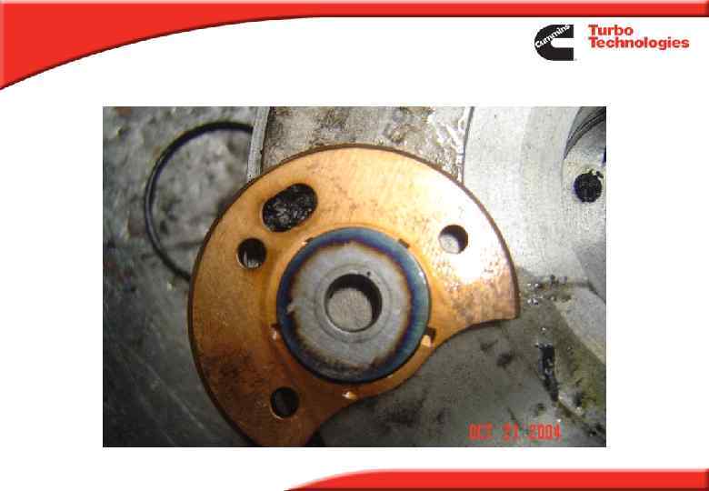
Oil Contamination New bearing Contaminated bearing Check the colour of the bearing, a natural darkening with age is acceptable. A duller, powdery surface is an indication of engine coolant in the oil - the same appearance will normally also be found on the thrust bearing.

Oil Delay Causes : Restricted oil feed pipes. Low oil level in the sump Blocked oil filter Long periods on Non – use Lack of priming Bronze particles on the shaft

Oil Starvation Cause : Oil pump failure Broken oil feed pipe No oil in engine.

Hot Shutdown - Overheating Cause: Hot shutdown of the engine, poor quality lub. oil, infrequent service intervals, check for heavy carbon deposit in the bearing housing.

Hot Shutdown Oil Leakage Blocked oil drain cavity Oil Drain

Hot Shutdown - Overheating

Failure Diagnosis: 340 300 260 Hot Shut Down from Peak Torque 1 min Idle Temp Limit of CD Oil 2 min Idle 220 3 min Idle 180 Bearing Temperature o. C Hot Shutdown 140 0 60 120 180 Time (secs) 240 300 360

Oil Leakage External - Common Causes : Loose / Damaged oil inlet and oil drain fittings. If fitting a new gasket and tightening the fittings does not stop the leak, then look for a damaged oil line or leaking centre housing. Internal Compressor & Turbine - Common Causes : Restriction in the turbo oil drain will ‘force’ oil past the split ring seals at both the turbine and compressor ends. Oil leakage at both ends simultaneously is a good indicator that this may be the problem Engine blow by pressure - which can be due to the engine crankcase vent being blocked by damage, plugging or icing.

Oil Leakage Restriction
 greater than 25 in water will ‘pull’")
Oil Leakage - Compressor An inlet ‘depression’(vacuum) greater than 25 in water will ‘pull’ oil past the compressor end split ring seal. THIS WILL NOT DAMAGE THE TURBO UNLESS THE THRUST BEARING FAILS. Typical cause is a blocked air intake filter or collapsed intake pipe.

Compressor End Oil Leakage

Compressor End Oil Leakage

Oil Leakage

Blow By Recirculation Future legislation may prohibit all uncontrolled engine emissions, including crankcase blow-by gases. CCV systems filter the crankcase emissions from § engine piston rings § valve stem leakage § turbocharger seal leakage § air compressor leakage These are generally routed to the turbocharger compressor inlet

Compressor fouling due to CCV system • Oil deposit build up can be significant over a period of time

Impeller LCF - Defects Duty cycle Defect presence raises local stresses and initiates fatigue Defects have variety of sizes and appearances There are three common failure locations - back face, suction side exducer blade root and the bore (highest stresses) Back Face

Impeller LCF - Defects Blade Root - Inclusion Blade root - Linear/oxide blow

Impeller LCF - Defects Bore inclusion Bore cavity Cause of failure could also be due to overspeed

Machined From Solid Impeller MFS Overview

x 1 - Base Material Fatigue Properties x 2 - Material selection and processing §Base materials properties improved in MFS impellers due to increased alloy content and fine grain structure from forging process §Inherently low level of oxides in wrought alloy used to make MFS impellers §Fine grain structure in MFS leads to improved fatigue life

MFS Impeller

x 1 - Base Material Fatigue Properties x 2 - Material selection and processing §Fine grain structure in MFS leads to improved fatigue life Cast microstructure Forged microstructure
 related failures not experienced in MFS impellers Oxide casting defect")
Defect (casting process) related failures not experienced in MFS impellers Oxide casting defect
")
Balance - Related Failures Balance failures due to a manufacturing problem (hence Holset Responsibility) usually occur in very early life. (i. e. most within 500 km). If a balance failure occurs in late life - it is normally caused by wheel foreign-object damage, turbo overspeed or tampering) Balance failure causes: Parts misaligned Rotor parts replaced without check-balancing Incorrect parts used.

Copy Turbochargers

Copy Turbos Introduction: Copies are flooding the market from China &Brazil. Many varieties Hosel, Hovte, Hobest and Honesty! They look good (to the untrained eye) Cheap: Approx. 1/2 price of original Holset Turbo

Copy Turbos Back to Back Engine tests: Three copies tested Results follow findings of wastegate settings Low boost and air flow Generally lower total efficiency, by up to 10% This would result in loss of power, higher fuel consumption and higher emissions.

Copy Turbos Holset Vs Copy 1

VIDEO

Copy MAN Turbo HOLSET genuine turbo Copy turbo – See nut, machining and the shape of the struts.

Copy MAN Turbo Genuine Copy Turbo – No washers on the screws, machining, flat on the wastegate rod. PS – ignore the shape of the bracket. Genuine

Copy MAN Turbo Holset Copy turbo – Hose clip and hole in the capsule

Impeller Locknut Copy Genuine

Oil Seal Plate Retaining Ring Copy Genuine Difference Machined

Compressor Housing Retaining Ring Genuine Copy Machined Difference

Turbine Housing Screws Genuine Copy

Installing a Turbocharger

Technology

® Holset VGT Overview

Turbocharger Basics – Fixed Geometry § Turbochargers consist of Compressor Stage Bearing System an exhaust-gas driven turbine connected to and driving a radial compressor, providing a Turbine Stage boosted air supply to the engine. § At a given engine speed, turbo speed (hence boost pressure) can be changed ONLY by changing fuelrate. - i. e. at a fixed Area fuelling rate, boost pressure is also fixed.

Turbocharger Basics – Wastegates A wastegate mechanism functions, by allowing some of the exhaust gas to bypass the turbine – thus limiting turbo speed & boost pressure. Typically the wastegate valve is only opened at high engine speeds & loads (used to prevent turbo speed or boost pressure from exceeding safe levels).

Turbocharger Basics Watch out ! Excessive turbo speed

VGT - Electronic Control Strategy 1 Wastegate Valve Open

VGT - Electronic Control Strategy 1

Holset VGTTM – Performance benefit
 - Basics § By continuously varying the turbine housing’s critical area")
Variable Geometry (VG) - Basics § By continuously varying the turbine housing’s critical area the exhaust gas can now vary the speed of the turbo, boost pressure and exhaust manifold pressure – independent of engine speed and load. § Various ways of achieving Variable Geometry (VG)
 Swing Vane – non Holset § Turbine wheel is surrounded by")
Variable Geometry (VG) Swing Vane – non Holset § Turbine wheel is surrounded by a ring of nozzle guide vanes. § Flow area varied by changing the angle of these vanes in unison.

Holset VGTTM - One Piece Sliding Nozzle

Holset VGTTM - One Piece Sliding Nozzle Fewer moving parts Nozzle carried and moved by 2 rods Fewer potential wear sites

VGT a

Holset VGTTM - One Piece Sliding Nozzle ring fully closed Nozzle ring in mid position Nozzle ring fully open • Min. turbine volute exit area • Reducing turbine volute exit area • Increasing exhaust manifold pressure • Increasing shaft speed • Increasing turbo boost • Max. turbine volute exit area • Max. exhaust manifold pressure • Max. shaft speed • Max. turbo boost • Min. exhaust manifold pressure • Min. shaft speed • Min. turbo boost

VGT System - Pneumatic Actuation

Actuator development for VGTTM 1998 Pneumatic 2002 Electric Type 1 2007 Electric Type 2

2007 Type 2 SMART electric actuation 1

2007 Type 2 SMART electric actuation

VGT System - Electronic Actuation

2007 Type 2 SMART electric actuation §No external moving parts – direct fit on bearing housing §On-board microprocessor – relieves load on engine ECU §Position request from engine ECU via CAN network §Sends status message back to engine ECU: §Actual position v target position §Internal temperature §Motor effort

2007 Type 2 SMART electric actuation § An on-board thermistor monitors temperature. Current limiting is applied if the internal temperature exceeds a safe limit. § Motor-effort is monitored, and a de-rate applied under limiting conditions. § Has integral event log: 250 error codes – retrievable through OBD connection – or via Holset hardware and software

2007 Type 2 SMART electric actuation Aspect System: Interface Hardware & Software Actuator “T” Cable Std USB cable Aspect Interface Box Holset SOFTWARE Interface Box

2007 Type 2 SMART electric actuation Diagnosis § We can see the number of hours run and life history § e. g what temperature and load – and for how long

Turbocharger Basics – Variable Geometry benefits include: § Modulate EGR flow-rate § Reduce emissions § Higher engine power density § Increase engine ‘usable’ speed range § Increase low speed torque § Improve transient response & ‘driveability’ § Enhance engine braking

Any Questions? Thank You
Turbo Cummins 2010 Presentation.ppt