50870bf404dd41f2935f019b35ff5725.ppt
- Количество слайдов: 52


Tower Designs – the Good, the Bad and the Ugly (and a few geeky topics) Richard P. Biby, P. E. Waterford Consultants, LLC Waterford, VA 20197 (540) 882 -4290 rich@Waterfordconsulting. com This document contains copyrighted information of © 2006 Waterford Consultants, LLC and others

Who Am I l l l l l BS & MS Electrical Engineering & Computer Engineering, George Washington University, Washington, DC Registered Professional Engineer (VA) Former CTO of Crown Castle International, Inc. Owner of 20 ish towers in the DC / VA area Owner of Fryers Tower Source Publisher, AGL Magazine Founder and Chief Technology Officer of Waterford Consultants, LLC Active in analysis of Non-Ionizing Radiation for approximately 10 years Founder of Sitesafe, Inc.

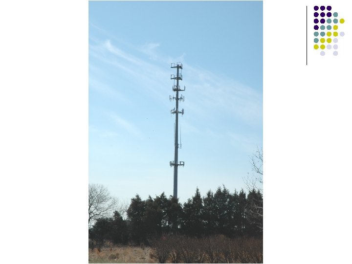
What RF Engineers Want l l l 20’ Tip to Tail Vertical Separation Interleave 800 MHz and 1900 MHz To be at the top of the tower No visual impairment between antenna and cell phone To be the only carrier on the tower Three antennas (Cellular), Two antennas (PCS)

What RF Engineers Usually Get l l l 20’ Tip to Tail Vertical Separation Interleave 800 MHz and 1900 MHz To be at the top of the tower No visual impairment between antenna and cell phone To be the only carrier on the tower Three antennas (Cellular), Two antennas (PCS)

What RF Engineers Will Accept (If management, the attorneys, regulatory affairs, operations, construction and real estate insists) l l l 20’ Tip to Tail Vertical Separation Interleave 800 MHz and 1900 MHz To be at the top of the tower No visual impairment between antenna and cell phone To be the only carrier on the tower Three antennas (Cellular), Two antennas (PCS)

Why 20’ Tip to Tail? l Interference l l l Performance l l Physically increasing spacing between antennas reduces amount of energy from one carrier’s TX antennas into another carrier’s RX antennas Industry “standard” which could use some additional research A system can receive weaker signals if there is no large source of background noise Could result in less sites ($$ savings)

Why 20’ Tip to Tail? l Few documented Interference issues when spacing closer Why Interleave 800 & 1900 MHz? l Reduction in interference l 800 MHz antennas receive 1900 MHz signals less efficiently then a 1900 MHz receive antenna, and vice versa. Vertically interleaving 800 & 1900 MHz carriers essentially doubles the separation spacing

To be at the Top of the Tower l l l Best position for Coverage, transmit and receive Will, typically, cost the most to be on top Carriers willing to be anchor tenant will often end up paying more to secure top spot Best position for reduced interference May have increased lightining exposure

No Visual Impairment Between Antenna and Cell Phone l l Any visual impairment will have an effect (negatively) on the effective radiated power (ERP) of the site, reducing coverage, increasing costs, and will also reduce the mobile units ability to talk back – either reducing coverage or requiring phone to transmit at higher power, reducing battery life. Not as big an issue in dense, highly populated areas where coverage will be limited by capacity constraints rather than coverage.
, Two antennas (PCS) l l l Cellular systems typically have two")
Three antennas (Cellular), Two antennas (PCS) l l l Cellular systems typically have two receive antennas (for space receive diversity) and one transmit (no diversity needed on transmit) PCS systems typically have one antenna which is receive only and one that transmits and receives Some systems may have a forth antenna for transmission if the site is very heavily loaded.

A Method For Combating Rayleigh Fading Polarization Diversity Use where Space Diversity Isn’t convenient l Sometimes zoning considerations or aesthetics preclude using separate diversity receive antennas l Dual-polarized antenna pairs within a single radome are becoming popular l Antenna pair within one radome can be V-H polarized, or diagonally polarized V+H or +/ A B l Each individual array has its own independent feedline A B Antenna A Antenna B Combined

Cross Polarization

Antenna Mounting Considerations Estimating Isolation Between Antennas l Often multiple antennas are needed at a site and interaction is troublesome Electrical isolation between antennas l Coupling loss between isotropic antennas one wavelength apart is 22 d. B l 6 d. B additional coupling loss with each doubling of separation l Add gain or loss referenced from horizontal plane patterns l Measure vertical separation between centers of the antennas l l vertical separation usually is very effective One antenna should not be mounted in main lobe and near-field of another l Typically within 10 feet @ 800 MHz

A Method For Combating Rayleigh Fading Space Diversity D l l l Signal received by Antenna 1 Signal received by Antenna 2 l Fortunately, Rayleigh fades are very short and last a small percentage of the time Two antennas separated by several wavelengths will not generally experience fades at the same time “Space Diversity” can be obtained by using two receiving antennas and switching instant-by-instant to whichever is best Required separation D for good decorrelation is (10 -20) l Combined Signal l D = (12 -24) ft. @ 800 MHz. D = (5 -10) ft. @ 1900 MHz.

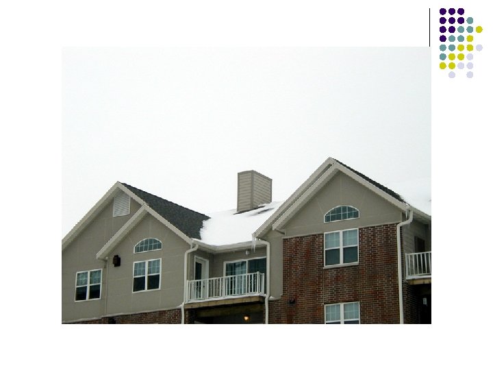

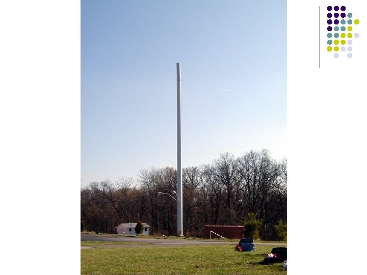
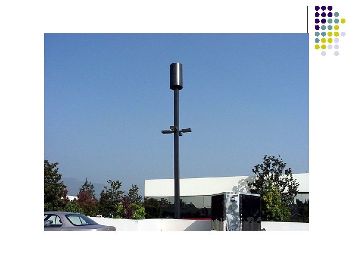

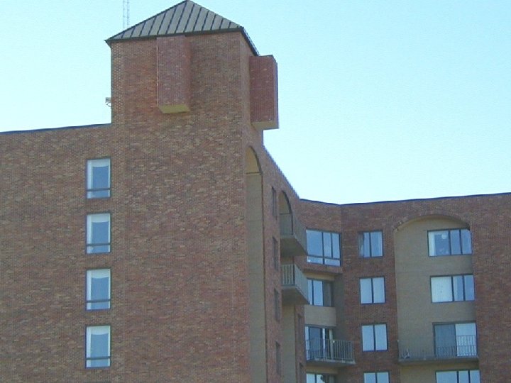
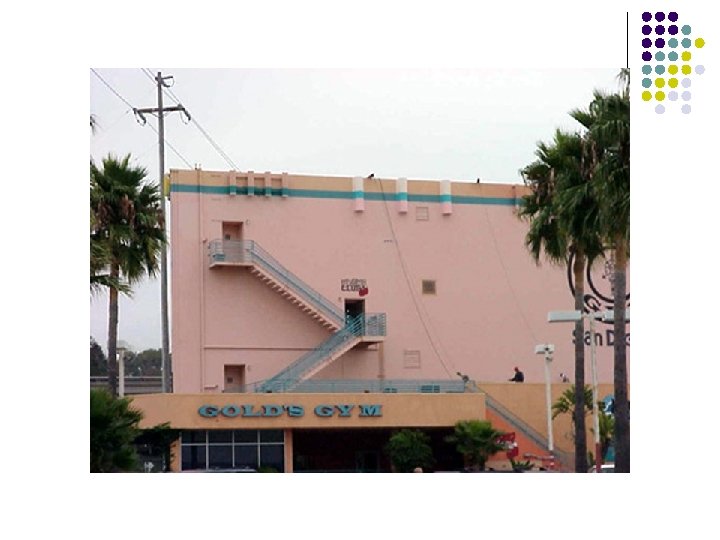


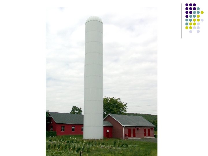
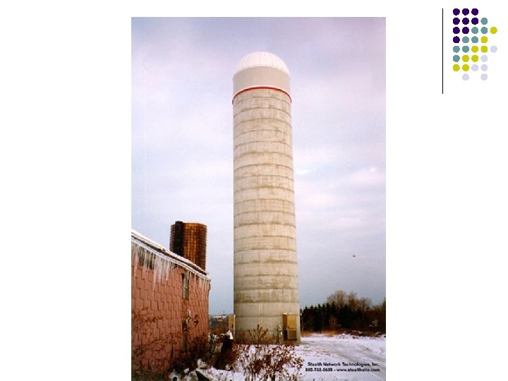


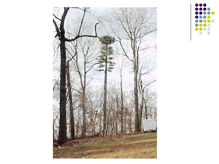

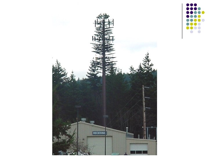
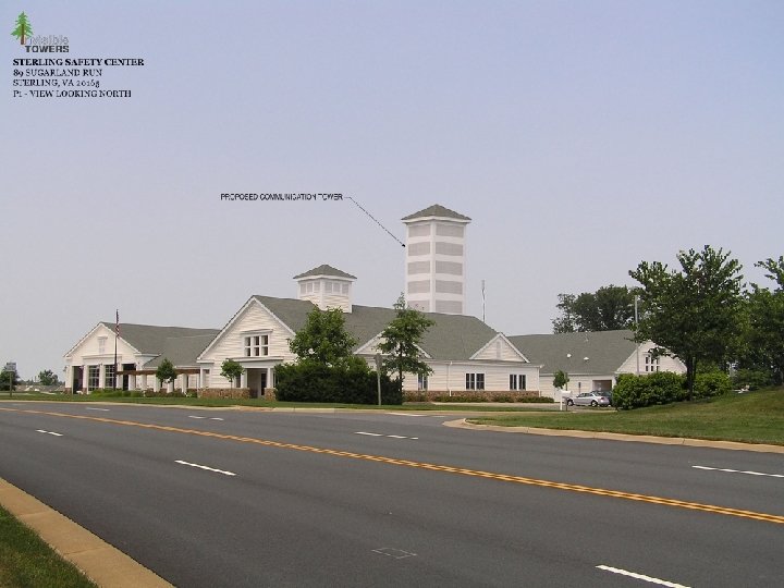
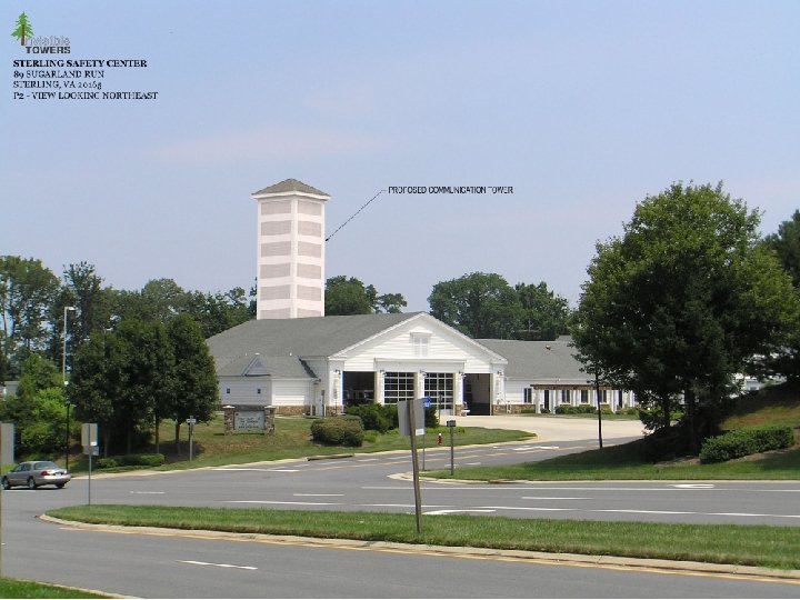

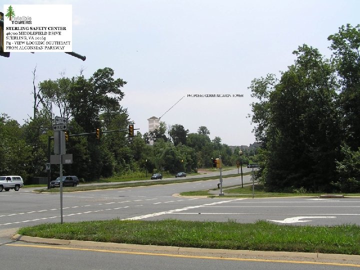


Summary of Alternative Towers l Pros l Reduced Visual Impact l Cons l l Increased costs (2, 3 or 4 times) Reduced Number of carriers per site Higher operational costs Increased Engineering Complexity & Reduced performance

Special Thanks To… Much of the material in this presentation has been developed by Mr. Scott Baxter, P. E. and is used with his permission. Stealth Technologies Invisible Towers, Inc.
")
Fun with Antennas (Time Permitting)

Basic Antenna Characteristics Radiation In Different Directions Minimum Radiation: l contributions out of phase, cancel l Maximum Radiation: TX contributions in phase, reinforce Minimum Radiation: contributions out of phase, cancel l Each “slice” of the antenna produces a definite amount of radiation at a specific phase angle Strength of signal received varies, depending on direction of departure from radiating antenna l In some directions, the components add up in phase to a strong signal level An antenna’s directivity is the same for transmission & reception

Basic Antenna Characteristics Antenna Gain l Antennas are passive devices: they do not produce power l l l Can only receive power in one form and pass it on in another, minus incidental losses Cannot generate power or “amplify” Omni-directional Antenna However, an antenna can appear to have “gain” compared against another antenna or condition. This gain can be expressed in d. B or as a power ratio. It applies both to radiating and receiving A directional antenna, in its direction of maximum radiation, appears to have “gain” compared against a non-directional antenna Gain in one direction comes at the expense of less radiation in other directions Antenna Gain is RELATIVE, not ABSOLUTE l When describing antenna “gain”, the comparison condition must be stated or implied Directional Antenna

Reference Antennas Antenna Gain And ERP - Examples l l Many wireless systems use omni antennas like the one shown in this figure These patterns are drawn to scale in E-field radiation units, based on equal power to each antenna Notice the typical wireless omni antenna concentrates most of its radiation toward the horizon, where users are, at the expense of sending less radiation sharply upward or downward The (typical) wireless antenna’s maximum radiation is 12. 1 d. B stronger than the isotropic (thus 12. 1 d. Bi gain), and 10 d. B stronger than the dipole (so 10 d. Bd gain). Gain Comparison 12. 1 d. Bi 10 d. Bd Isotropic Dipole Omni Isotropic Dipole Typical Wireless Omni Antenna Gain 12. 1 d. Bi or 10 d. Bd

Radiation Patterns Key Features And Terminology An antenna’s directivity is expressed as a series of patterns l l l Typical Example Horizontal Plane Pattern The Horizontal Plane Pattern graphs the radiation as a function of azimuth (i. e. . , direction N-E-S-W) The Vertical Plane Pattern graphs the radiation as a function of elevation (i. e. . , up, down, horizontal) Antennas are often compared by noting specific landmark points on their patterns: l l l -3 d. B (“HPBW”), -6 d. B, -10 d. B points Front-to-back ratio Angles of nulls, minor lobes, etc. Notice -3 d. B points 0 (N) 0 -10 -20 -30 d. B 270 (W) 10 d. B points Main Lobe nulls or a Minor minim Lobe Front-to-back Ratio 180 (S) 90 (E)

Antennas used in Wireless Omni Antennas - Collinear Vertical Arrays The family of omni-directional wireless antennas: l Number of elements determines l Physical size l Gain l Beamwidth, first null angle l Models with many elements have very narrow beamwidths l Require stable mounting and careful alignment l Watch out: be sure nulls do not fall in important coverage areas l Rod and grid reflectors are sometimes added for mild directivity Examples: 800 MHz. : d. B 803, PD 10017, BCR 10 O, Kathrein 740 -198 1900 MHz. : d. B-910, ASPP 2933 Typical Collinear Arrays Number of Elements 1 2 3 4 5 6 7 8 9 10 11 12 13 14 Power Gain 1 2 3 4 5 6 7 8 9 10 11 12 13 14 Gain, d. B 0. 00 3. 01 4. 77 6. 02 6. 99 7. 78 8. 45 9. 03 9. 54 10. 00 10. 41 10. 79 11. 14 11. 46 Angle n/a 26. 57° 18. 43° 14. 04° 11. 31° 9. 46° 8. 13° 7. 13° 6. 34° 5. 71° 5. 19° 4. 76° 4. 40° 4. 09° Vertical Plane Pattern beamwidth -3 d. B Angle of first null

Transmission Line Characteristics Some Practical Considerations l Transmission lines practical considerations l Periodicity of inner conductor supporting structure can cause VSWR peaks at some frequencies, so specify the frequency band when ordering l Air dielectric lines l lower loss than foam-dielectric; dry air is excellent insulator shipped pressurized; do not accept delivery if pressure leak Foam dielectric lines l l simple, low maintenance; despite slightly higher loss small pinholes and leaks can allow water penetration and gradual attenuation increases Air Dielectric Foam Dielectric

Antenna Downtilt Vertical Depression Angles l Basic principle: important to match vertical pattern against intended coverage targets l Compare the angles toward objects against the antenna vertical pattern -- what’s radiating toward the target? Don’t position a null of the antenna toward an important coverage target! Sketch and formula l Notice the height and horizontal distance must be expressed in the same units before dividing (both in feet, both in miles, etc. ) l l Depression angle Horizontal distance = Arc. TAN ( Vertical distance / Horizontal distance ) Vertical distance

Antenna Selection/Installation Scenario Reduce radiation interference to another cell Vision User A User B The Vision l Radiate a strong signal toward everything within the serving cell, but significantly reduce the radiation toward the area of Cell B weak strong height difference 150 ft Reality 1 2 4 12 miles 1 2 = Arc. TAN ( 150 / ( 4 * 5280 ) ) = -0. 4 degrees = Arc. TAN ( 150 / ( 12 * 5280 ) ) = -0. 1 degrees The Reality l When actually calculated, it’s surprising how small the difference in angle is between the far edge of cell A and the near edge of Cell B l Delta in the example is only 0. 3 degrees!! l Let’s look at antenna patterns
50870bf404dd41f2935f019b35ff5725.ppt