

32ab9b33a4cd468be35308238be0b80d.ppt
- Количество слайдов: 41
 The Major Constraint • Standard over the road: – 4. 1 m high by 2. 6 m wide – Net weight 21 tons • Very expensive – > 4. 83 m high • Rail – 3. 4 m, and heights are limited to 4. 0 m.
 Available Materials Welding 2
 Typical Wind Tower Plant Global Wind Tower Solutions Sand Blast Fittings & QA (2 X MIG) 100% UT Internals Counter weight (1 X MIG) Aluminum Paint Doorway Welding Or (2 X SAW) (2 X FCAW) Plate Storage & Quality Cutting Courtesy: Lincoln Electric Circumferential Welding Plate Rolling and Tacking (1 X MIG) Flange to Can Ring to Can (2 X SAW) Longitudinal Welding (1 X SAW) Boxes With a Red Border Indicate Processes Involving Welding
 FACILITY AUTOMATION CONSIDERATIONS • • Establish Requirements, Develop Concepts, and Model Concepts. Ensure that the Process Flow and Facility expectations can be achieved with the equipment specified. . Wind Tower Welding Productivity Seminar
 Tower Manufacturing www. davi. com
 http: //www. directindustry. com/prod/davi-promau/sheet-metal-calendering-line-forwind-tower-16273 -367798. html
 Weldment • Weldment has three distinct zones – fusion zone • area of weldment that melted and resolidified • contains base and filler metal – HAZ • area of weldment that did not melt, but properties has changed due to the heat input • contains base metal – base metal • area of weldment that was unaffected by weld • contains base metal (obviously) Welding 7
 From Lincoln Electric Welding 8
 HAZ • Dependent on: – type of alloy – heat added – initial heat – cooling rate Welding Kalpakijan & Schmid: Manufacturing 9 Engineering and Technology”
 • Continuous solid wire electrode • shielding from outside source of gas") GMAW (MIG) • Continuous solid wire electrode • shielding from outside source of gas – Ar, He, CO 2, or most likely a mixture • weld metal also contains deoxidizers – improves weld quality • lends itself well to robotics Welding 10
GMAW (MIG) • Continuous solid wire electrode • shielding from outside source of gas – Ar, He, CO 2, or most likely a mixture • weld metal also contains deoxidizers – improves weld quality • lends itself well to robotics Welding 10
 Groover: “Fundamentals of Modern Manufacturing” Welding 11
 • Continuous tubular electrode • Shielding from: – solid flux in") FCAW (Flux Core) • Continuous tubular electrode • Shielding from: – solid flux in the middle – external shielding gas • Advantages over GMAW: – 4 to 8 X deposition rate out of position – 1. 5 X deposition rate in position • especially for weldments greater than. 5” – alloy opportunities by changing flux Figure from Lincoln Electric Welding 12
FCAW (Flux Core) • Continuous tubular electrode • Shielding from: – solid flux in the middle – external shielding gas • Advantages over GMAW: – 4 to 8 X deposition rate out of position – 1. 5 X deposition rate in position • especially for weldments greater than. 5” – alloy opportunities by changing flux Figure from Lincoln Electric Welding 12
 • Continuous tubular electrode • Shielding from solid flux") SSFCAW (Self Shielded Flux Core) • Continuous tubular electrode • Shielding from solid flux in the middle • Advantages over GMAW: – outdoor applications – alloy opportunities by changing flux Welding 13
SSFCAW (Self Shielded Flux Core) • Continuous tubular electrode • Shielding from solid flux in the middle • Advantages over GMAW: – outdoor applications – alloy opportunities by changing flux Welding 13
 • Continuous solid wire electrode • granular flux: – shielding –") SAW (Submerged Arc) • Continuous solid wire electrode • granular flux: – shielding – prevents spatter and sparks – insulation to allow deeper penetration • flat or horizontal position, circular • good quality, toughness, uniform properties • usually automated Welding 14
SAW (Submerged Arc) • Continuous solid wire electrode • granular flux: – shielding – prevents spatter and sparks – insulation to allow deeper penetration • flat or horizontal position, circular • good quality, toughness, uniform properties • usually automated Welding 14
 Welding Figure from Groover 15
 Welding 16 Cary: Modern Welding Technology
 Residual Stress • caused by contraction of metal during solidification and cooling • control or minimize by: – fixtures – procedures (order of welds) – parameters (speed, filler metal. . – preheat – stress relief – proper design Welding 17
 Figure from Lincoln Electric
 Figure from Lincoln Electric
 Global Wind Tower Solutions Entry Door Frame Welding • Can be welded with a variety of processes, but most commonly SAW or FCAW. • FCAW equipment recommendation: – CV 400/LN-7 Pro • FCAW consumable recommendation: – Ultra. Core® E 71 T-12 • Handheld SAW is preferred, but flux selection is critical due to metallurgical requirements, and flux feedability concerns. • Handheld equipment recommendation: – LN-9 Undercarriage with Flux Feeding System, combined with Idealarc® DC-600 or DC-655 • Handheld consumable recommendation – Lincolnweld® L-61 with 860, 960, or WTX™ Flux Slide from Lincoln Electric
 Cost Reduction Savings Potential In Summary Global Wind Tower Solutions AFTER 50º 6 mm 36 mm Plate • • Change Joint Configuration Decrease Joint Angle Increase Joint Land Improve Weld Procedure Use AC to Increase Deposition Eliminate Back Gouging Improved Energy Efficiency with Power Wave® Technology Slide from Lincoln Electric
 Global Wind Tower Solutions Longitudinal & Circumferential Welding Review • Typically Tandem, triple Tandem or Twin Tandem systems, utilizing 2, 3 or 4 wires and welding heads. • With 2 or 3 wire Tandem Arc these welds can be accomplished single pass per side up to 36 mm. • Multi-pass welds are used when there is poor fit-up, greater plate thickness and to improve weld toughness. • With 3 wires, single pass thickness of up to 40 mm may be achieved. • The Included Angle used on Bevels for Tandem Arc can be greatly decreased to 50 o maximizing productivity and enabling single pass per side welding. • Lincoln Electric Power Wave® AC/DC 1000® power sources are ideal in these applications, with proven productivity and quality increases, as well as the opportunity for significant cost reduction. Slide from Lincoln Electric
 Global Wind Tower Solutions Customer Success BEFORE 70º 36 mm 2 mm AFTER 50º 6 mm 36 mm • Transferring technologies developed for the pipeline industry, in 2002 Lincoln Electric developed a new procedure for Apoyos Metalicos • The new procedure replaced a 9 -pass single arc approach with a 2 -pass tandem arc procedure • Switched from CV to CC • Consumable recommendation for impacts at o. C; Lincolnweld® P 230, P 223, or WTX™ flux with 20 Lincolnweld® L-61 wire • Consumable recommendation for impacts at 40 o. C; Lincolnweld® WTX™ flux with Lincolnweld® L-61 wire • Cost Savings – greater than 50% reduction in weld time and consumable savings 13 mm Plate 19 mm Plate Slide from Lincoln Electric 36 mm Plate
 INTEGRATED SYSTEMS STRATEGY It is important to note that an effective automation “strategy” seamlessly ties together all of the necessary components - Controls - Fixturing - Power Supplies - Sensing - Process Monitoring - Networking - User Interface to consistently provide the desired cost and quality benefits. Each component needs to be considered to ensure it is not the weak link of the overall completely integrated system. Wind Tower Welding Productivity Seminar Slide from Lincoln Electric
 What is Important to Consider when Evaluating Automation - Experience • Supplier experience in Welding Automation Controls, as well as systems integration specifically for your application, will significantly help to ensure requirements are met and mistakes are not repeated. Process-Power Supplies-Sensors-Motion-etc. Unless your application is very unique, try not to be the guinea pig Wind Tower Welding Productivity Seminar Slide from Lincoln Electric
 Improving Subarc welding productivity • Productivity depends on: – Deposition rate – Set up time / operator skill – Fit up and edge prep – Steel quality / property requirements – Other bottlenecks – Defect Costs • Severity • Occurrence • Detection 26
 SAW Deposition Rates Single Electrode DC+ Diameter Current 2. 4 mm 3. 2 mm 4. 0 mm 4. 8 mm 600 Amps 800 Amps 900 Amps 1200 Amps 10 to 12 kg/hr is the baseline 27 Deposition Rate 8 Kg/hr 10 Kg/hr 12 Kg/hr 17 Kg/hr
 SAW Deposition Rates Twin Arc Diameter Current 2 x 1. 6 mm 2 x 2. 0 mm 2 x 2. 4 mm 980 Amps 1300 Amps 1400 Amps Deposition Rate 17 Kg 18 Kg 19 Kg 50% increase in deposition rate versus single wire DC+ • Power source must be capable and stable at high currents • Loss in penetration (return to back gouging…) • Good when fit up / joint preparation is not perfect • Can be used in tandem with single wire or another twin 28
 SAW Deposition Rates Multiple Arcs Number of Arcs 1 Configuration DC+ Deposition rate 12 Kg/hr 2 DC+/AC 22 Kg/hr 3 DC+/AC/AC 32 Kg/hr 4 DC+/AC/AC/AC 52 Kg/hr 5 DC+/AC/AC 63 Kg/hr Huge increases in deposition rate versus single wire DC+ High penetration allows modified joint design One pass per side decreases set up time 29
 Flux/wire consumption Weld volume V-butt joint X-butt joint bevel angle: 60º Bevel angle: 60º root face: 6 mm Thickness Volume 12 mm 14 mm 16 mm 18 mm 20 mm 22 mm 30 Thickness Volume 0. 41 Kg/m 0. 60 Kg/m 0. 79 Kg/m 1. 03 Kg/m 1. 45 Kg/m 1. 76 Kg/m 12 mm 14 mm 16 mm 18 mm 20 mm 22 mm 0. 19 Kg/m 0. 29 Kg/m 0. 41 Kg/m 0. 61 Kg/m 0. 70 Kg/m 0. 87 Kg/m
 Example of a 4 -wire SAW Procedure • • Lead arc: Second arc: Third arc: Fourth arc: DC+ 1000 amps, 32 volts AC 900 amps, 35 volts AC 800 amps, 38 volts AC 725 amps, 41 volts • All wires are 4. 0 mm diameter • All heat inputs are essentially the same 32
 4 Wire SAW Example: Lead Arc • In most cases the lead arc is DC+ • The low voltage focuses the arc current (resulting in deep penetration). Can provide up to 80% of the total penetration. 33
 4 Wire SAW Example: Arc 2 • The second arc increases penetration because of the proximity to the first arc. • Lower current, higher voltage produces a wider, shallower bead profile. 34
 4 Wire SAW Example: Arc 3 • Current lower than Arc 2; voltage higher. • This layer adds to the width of the bead. It should bring the weld metal approximately to the surface. 35
 4 Wire SAW Example: Arc 4 • Usually characterized by the lowest current and highest voltage. • Shapes the cap of the weld. Angle of electrode, voltage, current and flux type determine toe angles, cap height, shape. 36
.") Finished Weld • The sketch shows the complete weld bead (with a tack weld). • The heat input of each arc was very similar, but different shapes were created by manipulation of volts, amps, spacings and angles. 37
Finished Weld • The sketch shows the complete weld bead (with a tack weld). • The heat input of each arc was very similar, but different shapes were created by manipulation of volts, amps, spacings and angles. 37
 The Major Constraint • Standard over the road: – 4. 1 m high by 2. 6 m wide – Net weight 21 tons • Very expensive – > 4. 83 m high • Rail – 3. 4 m, and heights are limited to 4. 0 m.
 Modular Bolted

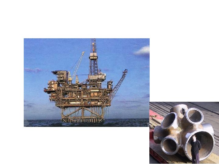
 Cast Weld Falk Lüddecke, Werner Rücker, Marc Seidel, Jens Assheuer: Tragverhalten von Stahlgussbauteilen in Offshore. Windenergie-Anlagen unter vorwiegend ruhender und nicht ruhender Beanspruchung