

882dccb64119bf121338eaad3604e7e7.ppt
- Количество слайдов: 38
 The LNF test setup Status as of 20140610
 Geometry of LNF setup Top and bottom trigger counters 3 KLOE-type tracking chambers 585 mm One BESIII-(COMPASS-)type test chamber 280 mm 70 mm
type test chamber") 3 KLOE-type tracking chambers One BESIII-(COMPASS-)type test chamber
3 KLOE-type tracking chambers One BESIII-(COMPASS-)type test chamber
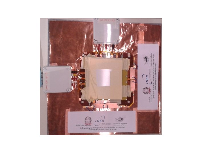
 The new BESIII-type test chamber, co-financed by INFN, IHEP and MAE
 The cosmic trigger • The 2 trigger counters for cosmic rays are 10 by 10 cm 2 scintillators (top PM HV: -1. 05 k. V, bottom PM HV: -1. 0 k. V) • PM signals from top and bottom are fed to CAEN N 417 low-threshold discriminators, stretched to 200 ns and coincidenced • The rate is 0. 1 Hz, with a few % random triggers • The coincidence output triggers 3 VME cards (tracking chambers electronics) and a Tektronix TDS 640 A for surveillance and monitoring
") Trigger NIM logic Trigger 62883 (actually a random coincidence!)
Trigger NIM logic Trigger 62883 (actually a random coincidence!)
 • The 2 gases (Ar and i. C 4 H") The gas system (Hdwr) • The 2 gases (Ar and i. C 4 H 10, isobutane) are in bottles in the gas house, 100 m away from the setup • Two separate gas lines transport the gas to MKS mass flowmeters, read out by a 647 C digital controller • Mass flowmeter ranges are 500 (Ar) and 50 (i. C 4 H 10) cm 3/min, nominal resolutions: 0. 1% of range • The gas mixture used is (90± 0. 5) cm 3/min (Ar) and (10± 0. 05) cm 3/min (i. C 4 H 10)
The gas system (Hdwr) • The 2 gases (Ar and i. C 4 H 10, isobutane) are in bottles in the gas house, 100 m away from the setup • Two separate gas lines transport the gas to MKS mass flowmeters, read out by a 647 C digital controller • Mass flowmeter ranges are 500 (Ar) and 50 (i. C 4 H 10) cm 3/min, nominal resolutions: 0. 1% of range • The gas mixture used is (90± 0. 5) cm 3/min (Ar) and (10± 0. 05) cm 3/min (i. C 4 H 10)
 and i. C 4 H 10 (Ch. 3) mass flowmeters The") Ar (Ch. 1) and i. C 4 H 10 (Ch. 3) mass flowmeters The gas mixing cylinder
Ar (Ch. 1) and i. C 4 H 10 (Ch. 3) mass flowmeters The gas mixing cylinder
 The readout controller
 • For safety reasons there is a shutoff valve") The gas/HV hdwr interlock (1) • For safety reasons there is a shutoff valve on the i. C 4 H 10 line in the gas house • This valve sometimes closes the flow w/o alarm, for reasons as yet unclear • Unprotected GEM chambers, under HV in pure Ar, are in great danger! • A hardware interlock is needed, currently in the design phase
The gas/HV hdwr interlock (1) • For safety reasons there is a shutoff valve on the i. C 4 H 10 line in the gas house • This valve sometimes closes the flow w/o alarm, for reasons as yet unclear • Unprotected GEM chambers, under HV in pure Ar, are in great danger! • A hardware interlock is needed, currently in the design phase
 • A 2. 5 bar Gems pressure transducer, immediately") The gas/HV hdwr interlock (2) • A 2. 5 bar Gems pressure transducer, immediately before the mass flowmeter, will convert pressure to a 4 -20 m. A current signal • An Arduino-system, designed and made in LNF, will read this signal every 10 s • If 3 consecutive readings go below threshold, this system will send a “Kill” signal to the HV controller, turning off all GEM chambers
The gas/HV hdwr interlock (2) • A 2. 5 bar Gems pressure transducer, immediately before the mass flowmeter, will convert pressure to a 4 -20 m. A current signal • An Arduino-system, designed and made in LNF, will read this signal every 10 s • If 3 consecutive readings go below threshold, this system will send a “Kill” signal to the HV controller, turning off all GEM chambers
 Gas/HV software interlock • Readings from the 647 C serial ports reach a Moxa NPORT 5450 serial server, that emulates via Ethernet 4 serial ports to the slow-control PC • The slow-control PC is a Virtual. Box Windows XP subsystem of the Scientific Linux 6 DAQ PC • In the XP subsystem, 2 Lab. View VIs (one Data. Socket publisher and one subscriber) monitor and log to disk gas flow readings • One additional subscriber VI implements a software interlock for the HV-controlling VI
 The Moxa NPORT 5450 Serial Server, with its Serial Port inputs and Ethernet connection
 The Windows XP Virtual. Box: the monitor VI is a Data. Socket publisher of date-stamped gas flow readings. The slow logger VI is a Data. Socket subscriber that writes gas flows to disk. The Watchdog VI analyzes flow and current readings and publishes the Alarm flag, to which the HV slow control subscribes.
 HV hardware • Based on a CAEN SY 1527 LC crate, with 2 boards – A 24 -channel A 1550 DN for the 3 tracking chambers – A 12 -channel A 1550 SN for the test BESIII chamber and the two trigger PM • For redundancy and crosscheck the HV state is echoed (and possibly changed in an emergency) using a local monitor and keyboard • Channel currents (below CAEN system capabilities) are read by a 24 -channel nano. Amperometer with 1 n. A resolution (design by LNF-SELF service)
 The CAEN controller with its Ethernet connection, and AUX video and keyboard cables. The SELF nano. Amperometer, with its CANBUS interface
 The 7 “physical” HV channels of a GEM • For each chamber we use 7 HV channels: Cathode HV 3 mm gap GEM 1 “Up” HV GEM 1 “Dn” HV 2 mm gap GEM 2 “Up” HV GEM 2 “Dn” HV 2 mm gap GEM 3 “Up” HV GEM 3 “Dn” HV Anode (readout), GND 1 mm gap
 The 7 logical HV channels of a GEM • The 3 “GEM” potentials determine gain: – Gain 1 is (exp) function of (HVG 1 up-HVG 1 dn) – Similarly for gains 2 and 3 – Overall gain = Gain 1*Gain 2*Gain 3 • The 4 “transfer” HV’s move electrons to the next stage: – (HVcathode-HVG 1 up) moves electrons away from cathode towards GEM 1: this is called “drift” field – Same for middle gaps – (HVG 3 dn-GND) moves electrons away from GEM 3 to the readout layer: this is called “induction” field
 The Lab. View VI for monitor and control of GEM channels. Communications with the SY 1527 LC crate are handled by an HV OPCServer low-level driver written by CAEN. This VI implements a gas/HV safety software interlock.
 “logical” Top/Mid/Bot V cathode -2. 76/-2.") HV for tracking chambers “physical” Top/Mid/Bot (k. V) “logical” Top/Mid/Bot V cathode -2. 76/-2. 75/-2. 74 Drift 1. /1. k. V/cm V G 1 Up -2. 46/-2. 45/-2. 44 Transfer 2 1. 5/1. 5 k. V/cm V G 1 Dn -2. 17/-2. 15/-2. 14 Transfer 3 1. 5/1. 5 k. V/cm V G 2 Up -1. 87/-1. 85/-1. 84 Induction 5/5/5 k. V/cm V G 2 Dn -1. 58/-1. 57/-1. 56 Gain 1 295/295 V V G 3 Up -1. 28/-1. 27/-1. 26 Gain 2 290/285 V V G 3 Dn -1. /-1. Gain 3 280/270/260 V These tables are kept for reference, they were used for the old KLOE 2 gas mixture
HV for tracking chambers “physical” Top/Mid/Bot (k. V) “logical” Top/Mid/Bot V cathode -2. 76/-2. 75/-2. 74 Drift 1. /1. k. V/cm V G 1 Up -2. 46/-2. 45/-2. 44 Transfer 2 1. 5/1. 5 k. V/cm V G 1 Dn -2. 17/-2. 15/-2. 14 Transfer 3 1. 5/1. 5 k. V/cm V G 2 Up -1. 87/-1. 85/-1. 84 Induction 5/5/5 k. V/cm V G 2 Dn -1. 58/-1. 57/-1. 56 Gain 1 295/295 V V G 3 Up -1. 28/-1. 27/-1. 26 Gain 2 290/285 V V G 3 Dn -1. /-1. Gain 3 280/270/260 V These tables are kept for reference, they were used for the old KLOE 2 gas mixture
 “logical” Top/Mid/Bot V cathode -3. 49") HV for tracking chambers “physical” Top/Mid/Bot (k. V) “logical” Top/Mid/Bot V cathode -3. 49 Drift 1. 5 k. V/cm V G 1 Up -3. 04 Transfer 2 3 k. V/cm V G 1 Dn -2. 76 Transfer 3 3 k. V/cm V G 2 Up -2. 16 Induction 5 k. V/cm V G 2 Dn -1. 88 Gain 1 280 V V G 3 Up -1. 28 Gain 2 280 V V G 3 Dn -1. Gain 3 280 V Gas mixture: Ar-i. C 4 H 10 90%-10%
HV for tracking chambers “physical” Top/Mid/Bot (k. V) “logical” Top/Mid/Bot V cathode -3. 49 Drift 1. 5 k. V/cm V G 1 Up -3. 04 Transfer 2 3 k. V/cm V G 1 Dn -2. 76 Transfer 3 3 k. V/cm V G 2 Up -2. 16 Induction 5 k. V/cm V G 2 Dn -1. 88 Gain 1 280 V V G 3 Up -1. 28 Gain 2 280 V V G 3 Dn -1. Gain 3 280 V Gas mixture: Ar-i. C 4 H 10 90%-10%
 The nano. Amperometer interface • The LNF-SELF nano. Amperometer, with a CANbus interface, is read via a Kvaser USBCan. II by a Lab. View set of VIs • For now, we monitor 13 channels – All 7 channels of the new BESIII test chamber – The 2 most critical channels of each tracking chamber: G 3 Up and G 3 Dn
 The LNF-SELF n. A-meter
 In the plot on the left, current time-histories for 6 “tracking” channels: the peaks appear normally in the chamber ramp-up phase. In the plot on the right, the same for all 7 channels of the new BESIII test chamber
 The tracking chambers • The 3 tracking chambers are KLOE 2 -type, designed and made by a LNF-Bari collaboration • Each chamber has X-Y orthogonal views, read by 2 GASTONE-64 chips, a project of LNF-Bari • The active area is 128 strip wide in X and Y • With 650 mm strip pitch, the active area is 8. 3· 8. 3 cm 2 wide
 X- and Y-strip boards, each board carries one GASTONE 64 chip above-board another below, reading digitally 128 strips
 The DAQ system • The GASTONE 64 chips are connected to VME boards via AUX cards, designs by INFN-Bari • The VME crate is controlled by a CAEN V 1718 master, DAQ software written by INFN-Ferrara
 The DAQ crate, connected via USB to the DAQ PC, running Scientific Linux 6 The 6 flat cables carry signals from the 2 views of the 3 tracking chambers
 The BESIII test chamber
 Trigger logic PMTop, discr. , 100 ns PMBot, discr. , 100 ns Scaler 1 Oscilloscope trigger Timing Unit 1 2 ms Veto from prog (End DAQ) Trig from prog (debug) Timing Unit 2 200 ns Scaler 2 Trigger VME
 DAQ software • 3 chambers, 2 orthogonal views for each, 2 GASTONE 64 for each view • Written and run in Ferrara by G. Cibinetto in a 1 -board system with 2 GASTONE 16 chips • Finished in LNF to read 3 boards with 4 GASTONE 64, check data consistency etc
 The GASTONE 64 chip • GASTONE 64 is one 64 -bit register that upon receiving a trigger is saved in a 32 -event FIFO • The 64 -bit register follows the 64 (discriminated) inputs and has a memory set according to a monostable (one per chip) • Noisier strips shorter monostable gate length • Slower trigger longer gate length
 DAQ numerology and def’s VMEBoard 0 Top connector Bottom connector Y view, chips 24 and 25 X view, chips 0 and 1 z y x VMEBoard 1 Top connector Bottom connector VMEBoard 2 Top connector Bottom connector Y view, chips 12 and 13 X view, chips 8 and 9 X view, chips 16 and 17 Y view, chips 20 and 21
 DAQ status • 12 GASTONE chips – 11 chips perform OK – 1 chip presently “flaky”(under investigation) • Loss of synchronization still present, cause unknown, but not a big problem • Optimal settings of thresholds and monostable length yet to be defined
 Results • Presently checking consistency of tracking chambers • Request 2 hits in both top and bottom chamber to define a cosmic track • Plot in the 3 rd chamber the residual “expectedmeasured” • Fit the residuals with a gaussian + 2 nd degree polynomial (no alignments made as yet)
 mm sy = (341± 14) mm") Single-view plots sx = (376± 18) mm sy = (341± 14) mm
Single-view plots sx = (376± 18) mm sy = (341± 14) mm
 mm sy = (316± 15) mm") 2 D-view plots sx = (402± 23) mm sy = (316± 15) mm
2 D-view plots sx = (402± 23) mm sy = (316± 15) mm