
Telecom Implementation Guideline-Flexi Multi Radio Site Solutions


installtion_of_wcdma_flexi_multi_radio_bts.ppt
- Размер: 4 Mегабайта
- Количество слайдов: 53
Описание презентации Telecom Implementation Guideline-Flexi Multi Radio Site Solutions по слайдам
Telecom Implementation Guideline-Flexi Multi Radio Site Solutions
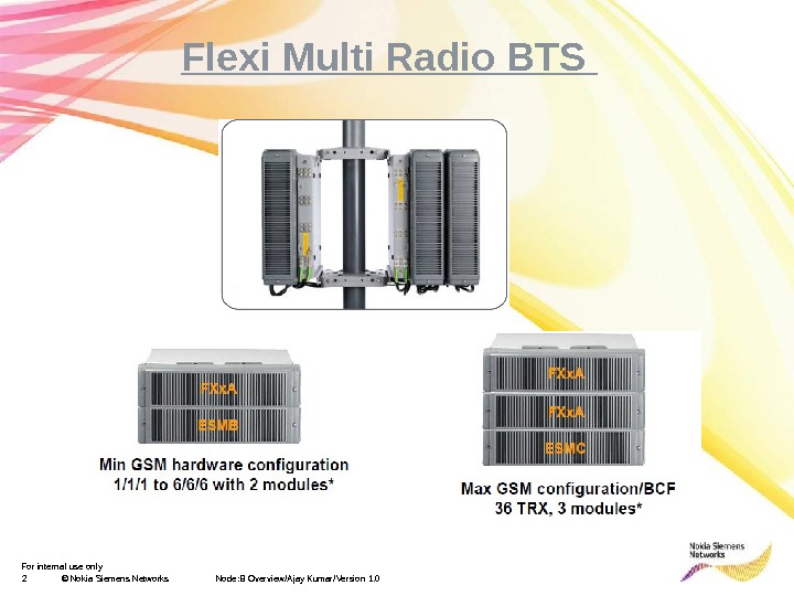
For internal use only 2 © Nokia Siemens Networks Node: B Overview/Ajay Kumar/Version 1. 0 Flexi Multi Radio BTS
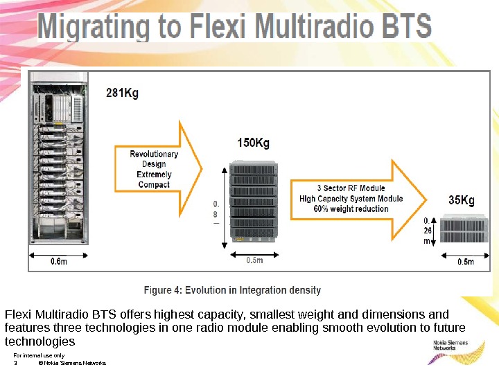
For internal use only 3 © Nokia Siemens Networks. Flexi Multiradio BTS offers highest capacity, smallest weight and dimensions and features three technologies in one radio module enabling smooth evolution to future technologies
For internal use only 4 © Nokia Siemens Networks Multi Radio Overview/Ajay Kumar/Version 1. 0 Multi Radio BTS Flexi Multi Radio BTS: is a base transceiver station that is part of the Nokia Siemens Networks Flexi BTS platform for GSM/EDGE, WCDMA, and LTE networks. It is a multi radio or multicarrier BTS that can use all these network technologies either in dedicated or concurrent mode of operation. • The Flexi Multiradio GSM/EDGE System Module provides baseband capacity for 18 or 36 GSM/EDGE TRXs depending on the version (ESMB or ESMC respectively). • The traffic capacity of Flexi Multiradio BTS depends on the radio capacity of the radio module, the baseband capacity and the transport capacity. The baseband capacity of GSM/EDGE and WCDMA/LTE are independent of each other as each technology uses separate System Modules and transport. • There are 3 radio branches in one Flexi Multiradio Radio Frequency module (FXxx). The TRX capacity of Flexi Multiradio BTS can be modified based on the traffic by increasing or decreasing the number of TRXs within a Radio Module branch, or by increasing the number of radio modules. Each radio module branch supports up to 6 GSM/EDGE TRXs. • The Radio module can be split into separate cells for multi-operator BTS. • Flexi Multiradio modules can be installed on a mast or a pole reducing the antenna feeder line length and thus increases the RF performance.
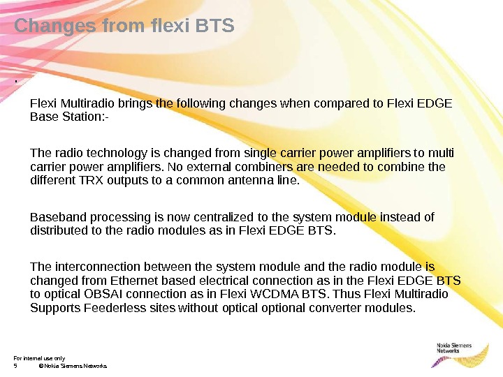
For internal use only 5 © Nokia Siemens Networks. Changes from flexi BTS Flexi Multiradio brings the following changes when compared to Flexi EDGE Base Station: — The radio technology is changed from single carrier power amplifiers to multi carrier power amplifiers. No external combiners are needed to combine the different TRX outputs to a common antenna line. Baseband processing is now centralized to the system module instead of distributed to the radio modules as in Flexi EDGE BTS. The interconnection between the system module and the radio module is changed from Ethernet based electrical connection as in the Flexi EDGE BTS to optical OBSAI connection as in Flexi WCDMA BTS. Thus Flexi Multiradio Supports Feederless sites without optical optional converter modules. .
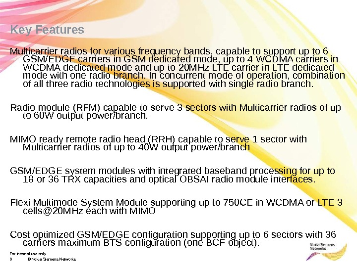
For internal use only 6 © Nokia Siemens Networks. Key Features Multicarrier radios for various frequency bands, capable to support up to 6 GSM/EDGE carriers in GSM dedicated mode, up to 4 WCDMA carriers in WCDMA dedicated mode and up to 20 MHz LTE carrier in LTE dedicated mode with one radio branch. In concurrent mode of operation, combination of all three radio technologies is supported with single radio branch. Radio module (RFM) capable to serve 3 sectors with Multicarrier radios of up to 60 W output power/branch. MIMO ready remote radio head (RRH) capable to serve 1 sector with Multicarrier radios of up to 40 W output power/branch GSM/EDGE system modules with integrated baseband processing for up to 18 or 36 TRX capacities and optical OBSAI radio module interfaces. Flexi Multimode System Module supporting up to 750 CE in WCDMA or LTE 3 cells@20 MHz each with MIMO Cost optimized GSM/EDGE configuration supporting up to 6 sectors with 36 carriers maximum BTS configuration (one BCF object).
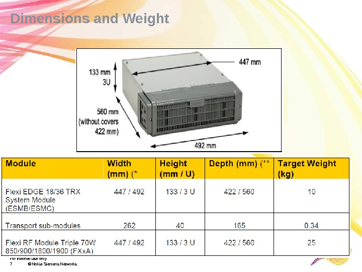
For internal use only 7 © Nokia Siemens Networks. Dimensions and Weight
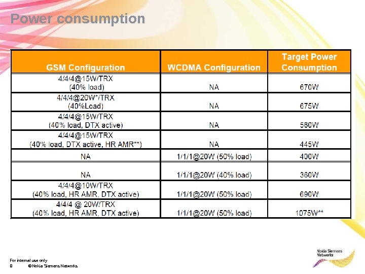
For internal use only 8 © Nokia Siemens Networks. Power consumption
For internal use only 9 © Nokia Siemens Networks Multi Radio Overview/Ajay Kumar/Version 1. 0 System Module
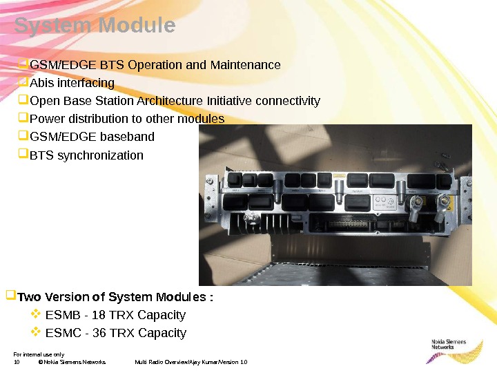
For internal use only 10 © Nokia Siemens Networks Multi Radio Overview/Ajay Kumar/Version 1. 0 System Module GSM/EDGE BTS Operation and Maintenance Abis interfacing Open Base Station Architecture Initiative connectivity Power distribution to other modules GSM/EDGE baseband BTS synchronization Two Version of System Modules : ESMB — 18 TRX Capacity ESMC — 36 TRX Capacity
For internal use only 11 © Nokia Siemens Networks. Flexi EDGE 18/36 TRX System Module Construction and Interfaces • 4 optical SFPs. OBSAI RP 3 -01 interface (3 Gbps). (3 for RF modules, 1 for 3 G/LTE system module connection or ESMB/ESMC chaining or alternatively all 4 for RF modules) • 48 VDC BTS power input terminals • 5 Power distribution I/Fs (4 for co-located RFMs, and 1 extra for any additional modules) • A slot for Integrated transport sub-module (various interface options available) • Ports for Power Module Alarms, Local Management and Q 1 • External Alarm Control port with 12 inputs and 6 outputs, or connectivity to EAC Ext. Module • Two ports for external synch. input or synch. extension to other co located base stations • Status-LED, Power LED and Power Push Button • Grounding terminal Q 1 FPA Optical RP 3 01 Synch out Synch in EAC LMP PWR Transmission PIU Power input Ground PWR PWR Status and Power LED 3 HU
For internal use only 12 © Nokia Siemens Networks. Flexi EDGE 18/36 TRX System Module ESMB/ESMC has an integrated transport unit which provides the physical transmission interfaces and the transport functionality of the BTS. Six different network interface alternatives are offered: E 1 symmetrical, E 1 unsymmetrical, T 1, Fast Ethernet, Gigabit Ethernet and Flexbus. These transport interface variants are same as with Flexi EDGE System Module ESMA. Flexi Multiradio BTS has Q 1 support for legacy networks, e. g. Talk-family BTS replacement, where network management is embedded in BSS using Q 1. Up to 34 Q 1 devices can be polled with Flexi Multiradio BTS. ESMx provides the OBSAI optical connectivity to the radios and to the other radio technology system module. It has 4 OBSAI RP 3 -1 interfaces. The OBSAI interfaces on both system modules can be used for radio connections in case of concurrent operation of several radio technologies.
For internal use only 13 © Nokia Siemens Networks. Flexi EDGE 18/36 TRX System Module The operating power can be supplied to the radios from ESMx. It has capability to distribute the 48 VDC power for up to 4 radios and one auxiliary device. The Flexi WCDMA system module can distribute the power for more radios in concurrent configurations. ESMx has an AUX power output (40. 5… 57 VDC, 5 A) for the site equipment like MWR ID units etc ESMB/ESMC has 12 integrated alarm inputs and 6 control outputs. The number of the external alarm inputs can be increased to 24 using optional Flexi alarm extension module (FSEB). The radios have also External alarm and control interfaces for Feederless or distributed site applications. RRH has 2 alarm inputs and RFM 4 alarm inputs and 4 control outputs that are compatible with the system module alarm interface. It also has an Element Manager Interface to connect the BTS to a Laptop computer, Flexi power alarm Interface which provides a Nokia Siemens Networks specific power alarm interface for the integrated power modules (FPMA, FPDA, MIBBU, i. PSU). And a Q 1 interface for managing legacy Nokia Siemens Networks equipment
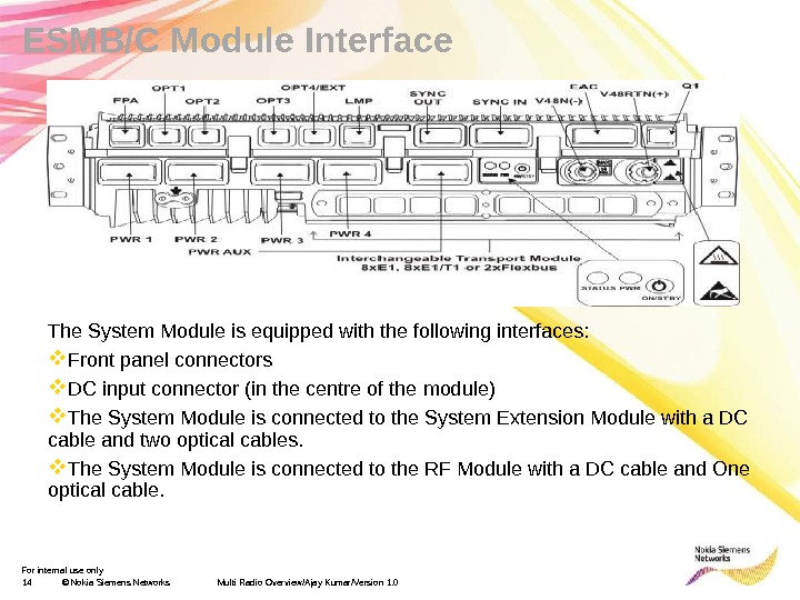
For internal use only 14 © Nokia Siemens Networks Multi Radio Overview/Ajay Kumar/Version 1. 0 ESMB/C Module Interface The System Module is equipped with the following interfaces: Front panel connectors DC input connector (in the centre of the module) The System Module is connected to the System Extension Module with a DC cable and two optical cables. The System Module is connected to the RF Module with a DC cable and One optical cable.
For internal use only 15 © Nokia Siemens Networks Multi Radio Overview/Ajay Kumar/Version 1. 0 RF Module
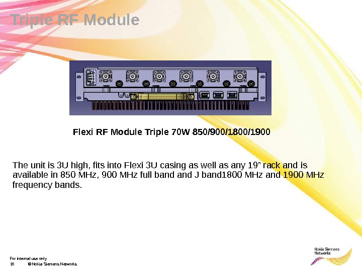
For internal use only 16 © Nokia Siemens Networks. Triple RF Module Flexi RF Module Triple 70 W 850/900/1800/1900 The unit is 3 U high, fits into Flexi 3 U casing as well as any 19” rack and is available in 850 MHz, 900 MHz full band J band 1800 MHz and 1900 MHz frequency bands.
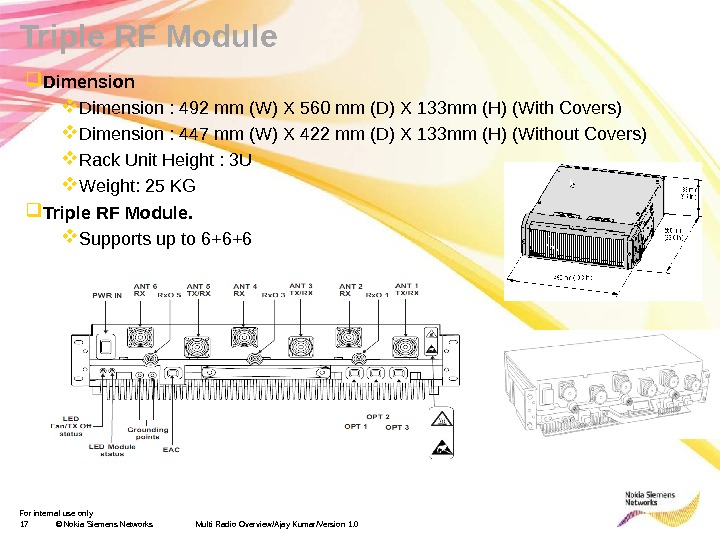
For internal use only 17 © Nokia Siemens Networks Multi Radio Overview/Ajay Kumar/Version 1. 0 Triple RF Module Dimension : 492 mm (W) X 560 mm (D) X 133 mm (H) (With Covers) Dimension : 447 mm (W) X 422 mm (D) X 133 mm (H) (Without Covers) Rack Unit Height : 3 U Weight: 25 KG Triple RF Module. Supports up to 6+6+
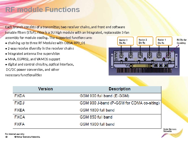
For internal use only 18 © Nokia Siemens Networks. RF module Functions Each branch consists of a transmitter, two receiver chains, and front end software tunable filters (STu. F). FXxx is a 3 U high module with an integrated, replaceable 3 -fan assembly for module cooling. The supported functions are: • chaining up to three RF Modules with OBSAI RP 3_01 • 2 -way receive diversity in the receiver chains • integrated antenna line supervision • MHA, EGPRS 2, and VAMOS support • digital and control circuitry, optical interface, DC/DC power conversion, and other necessary functionalities
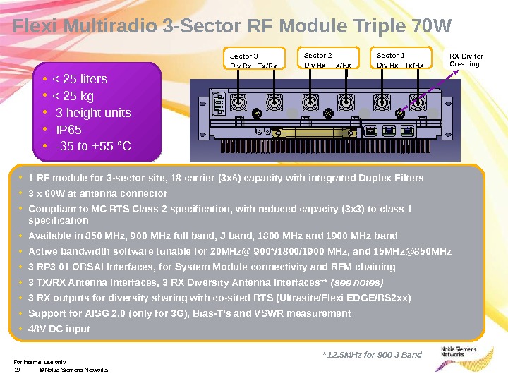
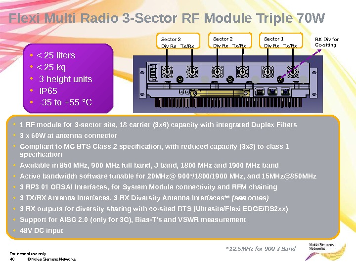
For internal use only 19 © Nokia Siemens Networks • < 25 liters • < 25 kg • 3 height units • IP 65 • -35 to +55 °CFlexi Multiradio 3 -Sector RF Module Triple 70 W • 1 RF module for 3 -sector site, 18 carrier (3 x 6) capacity with integrated Duplex Filters • 3 x 60 W at antenna connector • Compliant to MC BTS Class 2 specification, with reduced capacity (3 x 3) to class 1 specification • Available in 850 MHz, 900 MHz full band, J band, 1800 MHz and 1900 MHz band • Active bandwidth software tunable for 20 MHz@ 900*/1800/1900 MHz, and 15 MHz@850 MHz • 3 RP 3 01 OBSAI Interfaces, for System Module connectivity and RFM chaining • 3 TX/RX Antenna Interfaces, 3 RX Diversity Antenna Interfaces** (see notes) • 3 RX outputs for diversity sharing with co-sited BTS (Ultrasite/Flexi EDGE/BS 2 xx) • Support for AISG 2. 0 (only for 3 G), Bias-T’s and VSWR measurement • 48 V DC input Sector 3 Div Rx Tx/Rx Sector 2 Div Rx Tx/Rx Sector 1 Div Rx Tx/Rx RX Div for Co-siting * 12. 5 MHz for 900 J Band
For internal use only 20 © Nokia Siemens Networks. RF Module power requirements and output power Multi Radio Overview/Ajay Kumar/Version 1.
For internal use only 21 © Nokia Siemens Networks
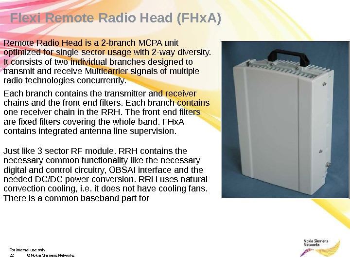
For internal use only 22 © Nokia Siemens Networks. Flexi Remote Radio Head (FHx. A) Remote Radio Head is a 2 -branch MCPA unit optimized for single sector usage with 2 -way diversity. It consists of two individual branches designed to transmit and receive Multicarrier signals of multiple radio technologies concurrently. Each branch contains the transmitter and receiver chains and the front end filters. Each branch contains one receiver chain in the RRH. The front end filters are fixed filters covering the whole band. FHx. A contains integrated antenna line supervision. Just like 3 sector RF module, RRH contains the necessary common functionality like the necessary digital and control circuitry, OBSAI interface and the needed DC/DC power conversion. RRH uses natural convection cooling, i. e. it does not have cooling fans. There is a common baseband part for
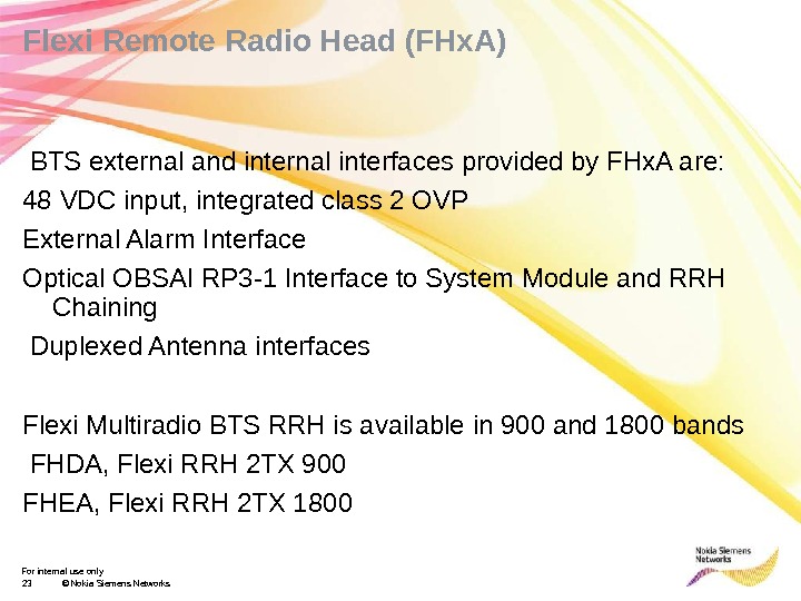
For internal use only 23 © Nokia Siemens Networks. Flexi Remote Radio Head (FHx. A) BTS external and internal interfaces provided by FHx. A are: 48 VDC input, integrated class 2 OVP External Alarm Interface Optical OBSAI RP 3 -1 Interface to System Module and RRH Chaining Duplexed Antenna interfaces Flexi Multiradio BTS RRH is available in 900 and 1800 bands FHDA, Flexi RRH 2 TX 900 FHEA, Flexi RRH 2 TX
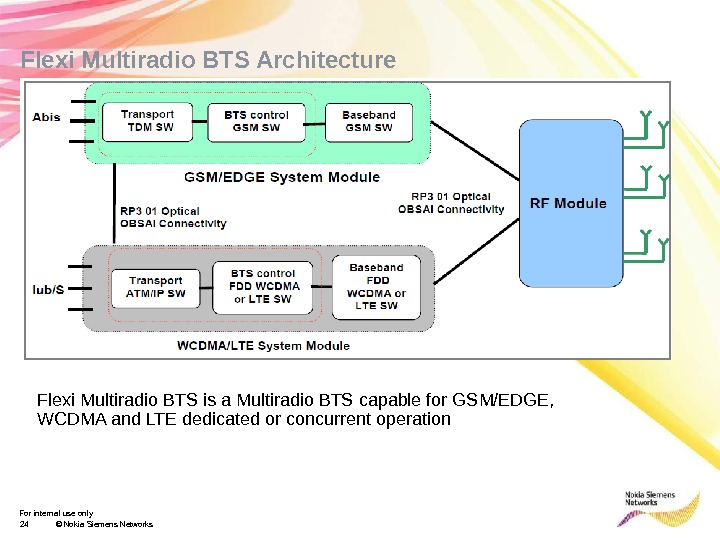
For internal use only 24 © Nokia Siemens Networks. Flexi Multiradio BTS Architecture Flexi Multiradio BTS is a Multiradio BTS capable for GSM/EDGE, WCDMA and LTE dedicated or concurrent operation
For internal use only 25 © Nokia Siemens Networks. Configurations RP 3 Configurations Optical OBSAI RP 3 -1 is used for the inter connection between the system module and the radio. There can be several radios simultaneously in a BTS configuration and they can be of different frequency band. The radios can be both 3 -sector radio modules and remote radio heads. The radios can be used in dedicated or in concurrent mode. GSM/EDGE and WCDMA/LTE have separate system modules ESMx and FSMx which can have common or independent connectivity to Radio Modules
For internal use only 26 © Nokia Siemens Networks. Configurations System module interconnection It is possible to inter connect the GSM/EDGE and the WCDMA/LTE system modules in concurrent configuration using RP 3 -1 connection. The connection can be used for synchronization only as well as for user and control data. an have an extension system module, which is another FSMx. The system modules are interconnected using RP 3 -1. The system modules within a BTS configuration are co located
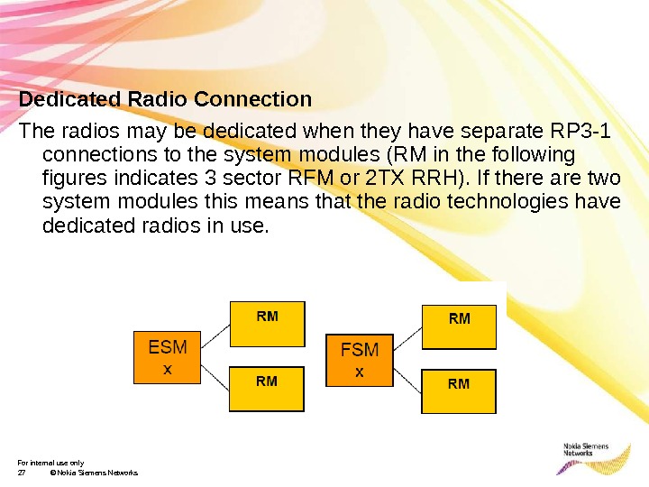
For internal use only 27 © Nokia Siemens Networks. Dedicated Radio Connection The radios may be dedicated when they have separate RP 3 -1 connections to the system modules (RM in the following figures indicates 3 sector RFM or 2 TX RRH). If there are two system modules this means that the radio technologies have dedicated radios in use.
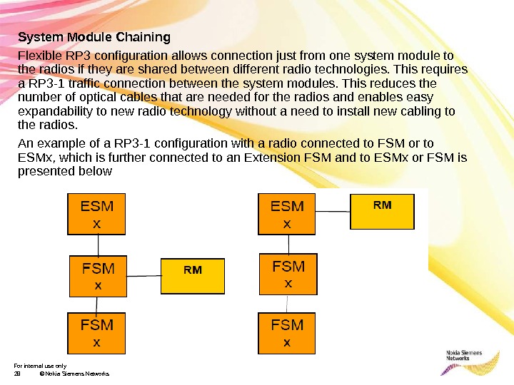
For internal use only 28 © Nokia Siemens Networks. System Module Chaining Flexible RP 3 configuration allows connection just from one system module to the radios if they are shared between different radio technologies. This requires a RP 3 -1 traffic connection between the system modules. This reduces the number of optical cables that are needed for the radios and enables easy expandability to new radio technology without a need to install new cabling to the radios. An example of a RP 3 -1 configuration with a radio connected to FSM or to ESMx, which is further connected to an Extension FSM and to ESMx or FSM is presented below
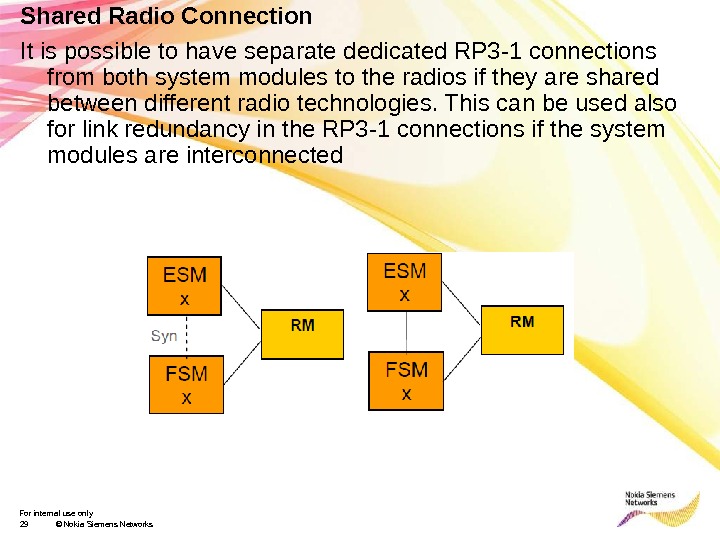
For internal use only 29 © Nokia Siemens Networks. Shared Radio Connection It is possible to have separate dedicated RP 3 -1 connections from both system modules to the radios if they are shared between different radio technologies. This can be used also for link redundancy in the RP 3 -1 connections if the system modules are interconnected
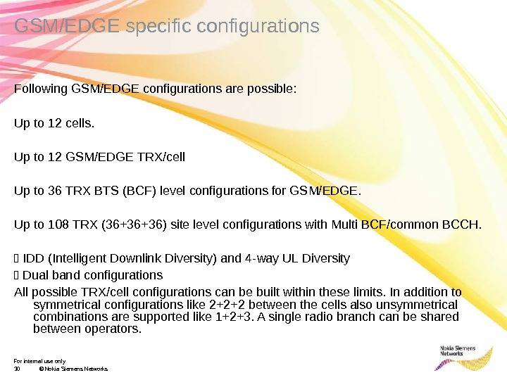
For internal use only 30 © Nokia Siemens Networks. GSM/EDGE specific configurations Following GSM/EDGE configurations are possible: Up to 12 cells. Up to 12 GSM/EDGE TRX/cell Up to 36 TRX BTS (BCF) level configurations for GSM/EDGE. Up to 108 TRX (36+36+36) site level configurations with Multi BCF/common BCCH. IDD (Intelligent Downlink Diversity) and 4 -way UL Diversity Dual band configurations All possible TRX/cell configurations can be built within these limits. In addition to symmetrical configurations like 2+2+2 between the cells also unsymmetrical combinations are supported like 1+2+3. A single radio branch can be shared between operators.
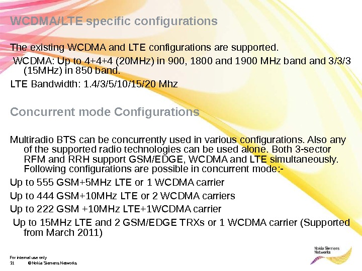
For internal use only 31 © Nokia Siemens Networks. WCDMA/LTE specific configurations The existing WCDMA and LTE configurations are supported. WCDMA: Up to 4+4+4 (20 MHz) in 900, 1800 and 1900 MHz band 3/3/3 (15 MHz) in 850 band. LTE Bandwidth: 1. 4/3/5/10/15/20 Mhz Concurrent mode Configurations Multiradio BTS can be concurrently used in various configurations. Also any of the supported radio technologies can be used alone. Both 3 -sector RFM and RRH support GSM/EDGE, WCDMA and LTE simultaneously. Following configurations are possible in concurrent mode: — Up to 555 GSM+5 MHz LTE or 1 WCDMA carrier Up to 444 GSM+10 MHz LTE or 2 WCDMA carriers Up to 222 GSM +10 MHz LTE+1 WCDMA carrier Up to 15 MHz LTE and 2 GSM/EDGE TRXs or 1 WCDMA carrier (Supported from March 2011)
For internal use only 32 © Nokia Siemens Networks. BTS Synchronization and transport solutions The Flexi Multiradio BTS transport solution is based on the Flexi platform. It supports chaining of the sites by having adequate number of interfaces and by supporting add-drop functionality which means that one common pipe backhaul for the complete radio site. Each system module uses its own transport plug in unit. The transport interfaces in the system modules can be chained so that only one physical connection leaves the BTS site. BTS transmission topologies such as hub sites and transmission loop masters are supported at the BTS site. The Abis and Dynamic Abis and Iub interfaces of the Flexi Multiradio BTS comply with the existing Flexi BSC and RNC. It is possible to reuse the existing BTS external transmission equipment with Flexi Multiradio BTS. The Flexi Multiradio BTS external transmission interfaces are compatible with the existing Nokia Siemens Networks products
For internal use only 33 © Nokia Siemens Networks. BTS Synchronization he Flexi Multiradio BTS is able to take its reference frequency from any of the following sources: External reference source, such as the LMU, GPS or other BTS PDH terrestrial transmission input BTS Internal Clock Source; to be used (for limited period) if external timing reference is lost In concurrent mode either ESMx or FSMx can be the synchronization master of Flexi Multiradio BTS while the other is a slave. The synchronization is done through RP 3 -1 connection between the system modules. Automatic master recovery in case of failure is supported by hardware. 2 G LMU Interface External 2 G synchronization can be provided by LMU (LMUB), which is an existing separate unit within the BTS. The BTS provides an interface for 2 G LMU clocks, control and power. In ESMx the interface is similar as in ESMA and the same cable can be used. The Q 1 interface of ESMx is used as LMU control interface. ESMx clock input (SIN) interface is used for LMU clocks and power.
For internal use only 34 © Nokia Siemens Networks. ESMx integrated transmission he Flexi Multiradio BTS GSM/EDGE system module uses the same transport options as with existing Flexi EDGE BTS. The transport interface comes in five different types of plug in units inserted into the system module (ESMx): FIEA : 8*E 1 asymmetrical FIPA : 8*E 1/T 1 symmetrical FIFA: 2*Flexbus; TNC-type 50 Ω coaxial connector FIQA: 1*SFP port, 2* Fast Ethernet, 4*E 1/T 1 symmetrical FIYA : 1*SFP port, 2* Fast Ethernet; 4*E 1/T 1 asymmetrical FIQB and FIYB will be supported with RG 20 SW release
For internal use only 35 © Nokia Siemens Networks. Mains power requirements Multi Radio Overview/Ajay Kumar/Version 1. 0 At the site there must be a main switch for disconnecting the BTS mains power. The disconnecting device shall disconnect both input supply poles simultaneously. The minimum cross-section of the mains power copper (Cu) conductor is following: o When 220 -240 VAC is used, power cables shall be 1. 5 — 2. 5 mm 2. o When 100 -110 VAC is used (split phase), power cables shall be 1. 5 — 2. 5 mm 2. o When 48 VDC is used, power cables shall be 10 -35 Sq. mm as per consumption and breaker ratings.
For internal use only 36 © Nokia Siemens Networks Presentation / Author / Date NSN Multi Radio Implementation Solutions
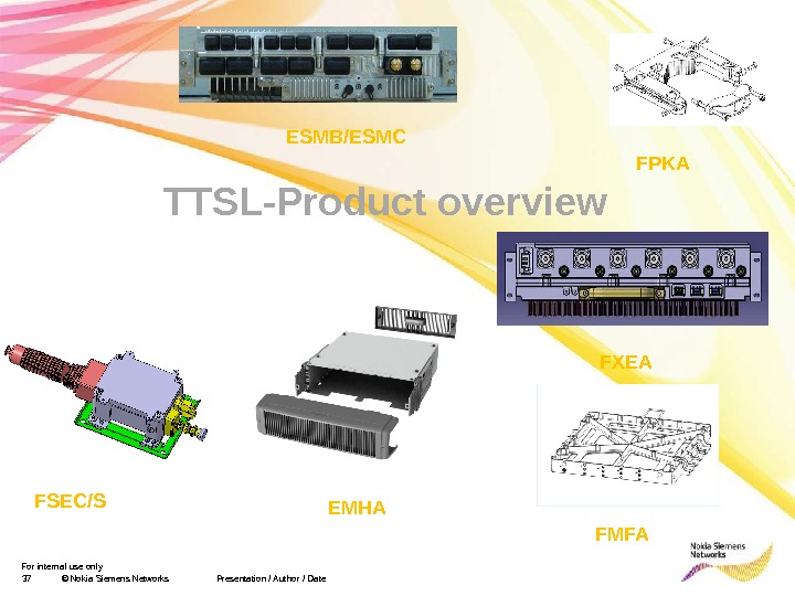
For internal use only 37 © Nokia Siemens Networks Presentation / Author / Date TTSL-Product overview ESMB/ESMC FXEA FPKA FMFAFSEC/S EMH
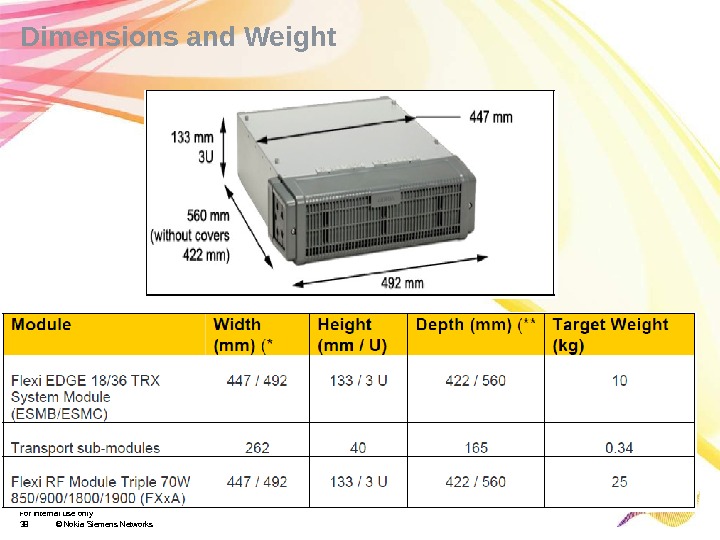
For internal use only 38 © Nokia Siemens Networks. Dimensions and Weight
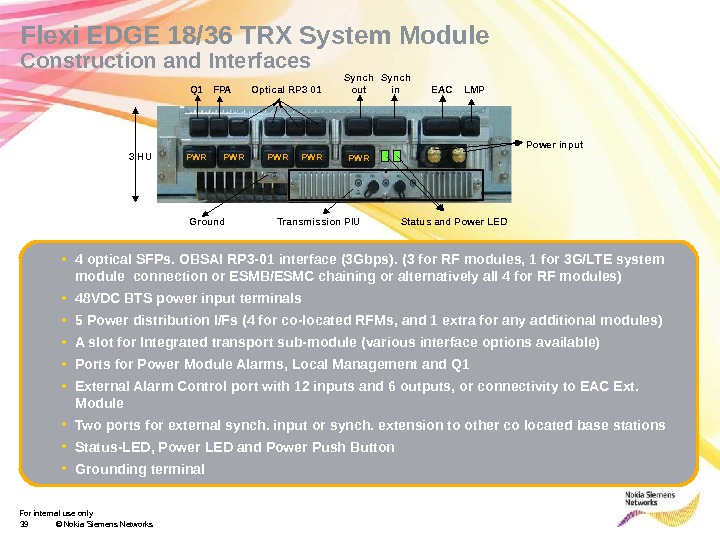
For internal use only 39 © Nokia Siemens Networks. Flexi EDGE 18/36 TRX System Module Construction and Interfaces • 4 optical SFPs. OBSAI RP 3 -01 interface (3 Gbps). (3 for RF modules, 1 for 3 G/LTE system module connection or ESMB/ESMC chaining or alternatively all 4 for RF modules) • 48 VDC BTS power input terminals • 5 Power distribution I/Fs (4 for co-located RFMs, and 1 extra for any additional modules) • A slot for Integrated transport sub-module (various interface options available) • Ports for Power Module Alarms, Local Management and Q 1 • External Alarm Control port with 12 inputs and 6 outputs, or connectivity to EAC Ext. Module • Two ports for external synch. input or synch. extension to other co located base stations • Status-LED, Power LED and Power Push Button • Grounding terminal Q 1 FPA Optical RP 3 01 Synch out Synch in EAC LMP PWR Transmission PIU Power input Ground PWR PWR Status and Power LED 3 HU
For internal use only 40 © Nokia Siemens Networks • < 25 liters • < 25 kg • 3 height units • IP 65 • -35 to +55 °CFlexi Multi Radio 3 -Sector RF Module Triple 70 W • 1 RF module for 3 -sector site, 18 carrier (3 x 6) capacity with integrated Duplex Filters • 3 x 60 W at antenna connector • Compliant to MC BTS Class 2 specification, with reduced capacity (3 x 3) to class 1 specification • Available in 850 MHz, 900 MHz full band, J band, 1800 MHz and 1900 MHz band • Active bandwidth software tunable for 20 MHz@ 900*/1800/1900 MHz, and 15 MHz@850 MHz • 3 RP 3 01 OBSAI Interfaces, for System Module connectivity and RFM chaining • 3 TX/RX Antenna Interfaces, 3 RX Diversity Antenna Interfaces** (see notes) • 3 RX outputs for diversity sharing with co-sited BTS (Ultrasite/Flexi EDGE/BS 2 xx) • Support for AISG 2. 0 (only for 3 G), Bias-T’s and VSWR measurement • 48 V DC input Sector 3 Div Rx Tx/Rx Sector 2 Div Rx Tx/Rx Sector 1 Div Rx Tx/Rx RX Div for Co-siting * 12. 5 MHz for 900 J Band
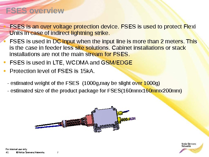
For internal use only 41 © Nokia Siemens Networks / • FSES is an over voltage protection device. FSES is used to protect Flexi Units in case of indirect lightning strike. • FSES is used in DC input when the input line is more than 2 meters. This is the case in feeder less site solutions. Cabinet installations or stack installations are not the main stream for FSES. • FSES is used in LTE, WCDMA and GSM/EDGE • Protection level of FSES is 15 k. A. — estimated weight of the FSES (1000 g, may be slight over 1000 g) — estimated size of the product package for FSES(160 mmx 200 mm)FSES overview
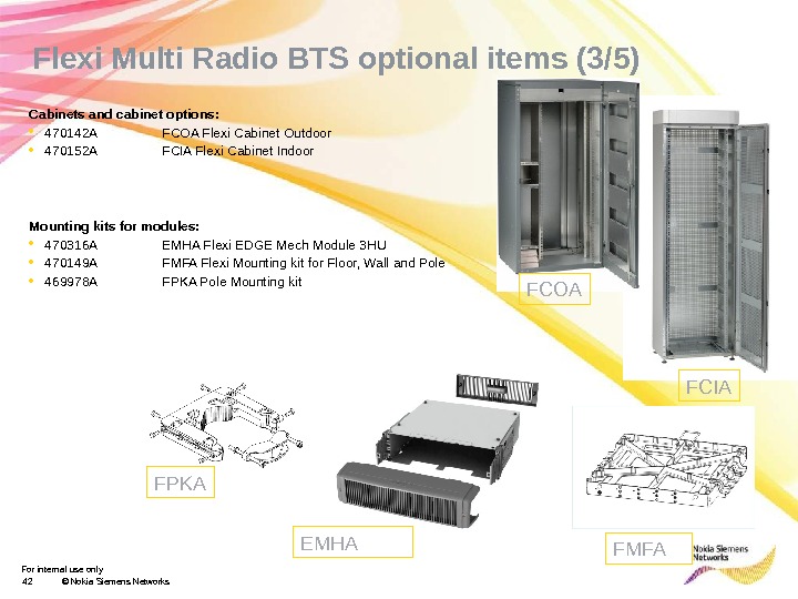
For internal use only 42 © Nokia Siemens Networks. Flexi Multi Radio BTS optional items (3/5) Cabinets and cabinet options: • 470142 A FCOA Flexi Cabinet Outdoor • 470152 A FCIA Flexi Cabinet Indoor Mounting kits for modules: • 470316 A EMHA Flexi EDGE Mech Module 3 HU • 470149 A FMFA Flexi Mounting kit for Floor, Wall and Pole • 469978 A FPKA Pole Mounting kit FCIAFCOA EMHAFPKA FM
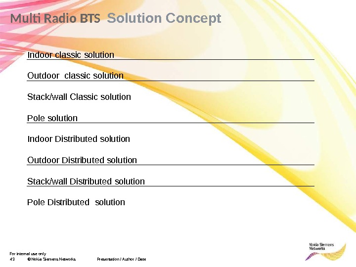
For internal use only 43 © Nokia Siemens Networks. Multi Radio BTS Solution Concept Presentation / Author / Date Indoor classic solution Outdoor classic solution Stack/wall Classic solution Pole solution Indoor Distributed solution Outdoor Distributed solution Stack/wall Distributed solution Pole Distributed solution
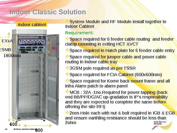
For internal use only 44 © Nokia Siemens Networks Indoor cabinet 1800 mm 600 Indoor Classic Solution System Module and RF Module install together in Indoor Cabinet Requirement: Space required for 6 feeder cable routing and feeder clamp mounting in exiting HCT &VCT Space required in Hatch plate for 6 feeder cable entry Space required for jumper cable and power cable routing in indoor cable tray 3 GSM pole required as per TSSR Space required for FCIA Cabinet (600 x 600 mm) Space required for Korne back mount frame and all infra Alarm patch to alarm panel MCB : 32 A -1 no. Required for power tapping (back end BB/PP/DG/AC up-gradation is IP’s responsibility and they are expected to complete the same before offering the site RFI) 2 nos Hole each with nut & bolt required in IGB & EGB and ensure earthling resistance should be less than 2 ohm 6 U ESMB EXx.
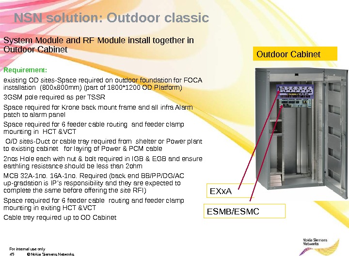
For internal use only 45 © Nokia Siemens Networks NSN solution: Outdoor classic System Module and RF Module install together in Outdoor Cabinet Requirement: existing OD sites-Space required on outdoor foundation for FOCA installation (800 x 800 mm) (part of 1800*1200 OD Platform) 3 GSM pole required as per TSSR Space required for Krone back mount frame and all infra Alarm patch to alarm panel Space required for 6 feeder cable routing and feeder clamp mounting in HCT &VCT O/D sites-Duct or cable tray required from shelter or Power plant to existing cabinet for laying of Power & PCM cable 2 nos Hole each with nut & bolt required in IGB & EGB and ensure earthling resistance should be less than 2 ohm MCB 32 A-1 no. 16 A-1 no. Required (back end BB/PP/DG/AC up-gradation is IP’s responsibility and they are expected to complete the same before offering the site RFI) Space required for 6 feeder cable routing and feeder clamp mounting in exiting HCT &VCT Cable trey required up to OD Cabinet Outdoor Cabinet ESMB/ESMC EXx.
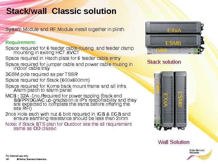
For internal use only 46 © Nokia Siemens Networks. Stack/wall Classic solution System Module and RF Module install together in plinth Requirement: Space required for 6 feeder cable routing and feeder clamp mounting in exiting HCT &VCT Space required in Hatch plate for 6 feeder cable entry Space required for jumper cable and power cable routing in indoor cable tray 3 GSM pole required as per TSSR Space required for Stack (600 x 600 mm) Space required for Korne back mount frame and all infra Alarm patch to alarm panel MCB : 32 A -1 no. Required for power tapping (back end BB/PP/DG/AC up-gradation is IP’s responsibility and they are expected to complete the same before offering the site RFI) 2 nos Hole each with nut & bolt required in IGB & EGB and ensure earthling resistance should be less than 2 ohm Note: If Stack BTS plan for Outdoor site the all requirement same as OD classic Stack solution Wall Solution EXx. A ESMBE X x. A E S M
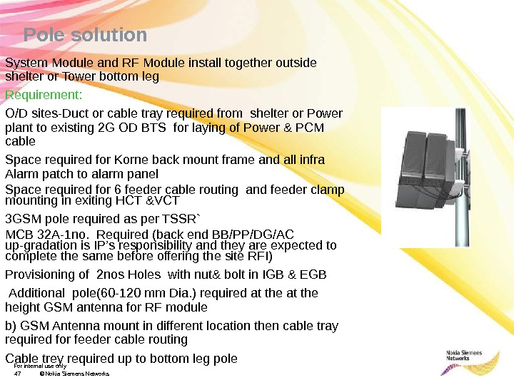
For internal use only 47 © Nokia Siemens Networks. Pole solution System Module and RF Module install together outside shelter or Tower bottom leg Requirement: O/D sites-Duct or cable tray required from shelter or Power plant to existing 2 G OD BTS for laying of Power & PCM cable Space required for Korne back mount frame and all infra Alarm patch to alarm panel Space required for 6 feeder cable routing and feeder clamp mounting in exiting HCT &VCT 3 GSM pole required as per TSSR` MCB 32 A-1 no. Required (back end BB/PP/DG/AC up-gradation is IP’s responsibility and they are expected to complete the same before offering the site RFI) Provisioning of 2 nos Holes with nut& bolt in IGB & EGB Additional pole(60 -120 mm Dia. ) required at the height GSM antenna for RF module b) GSM Antenna mount in different location then cable tray required for feeder cable routing Cable trey required up to bottom leg pole
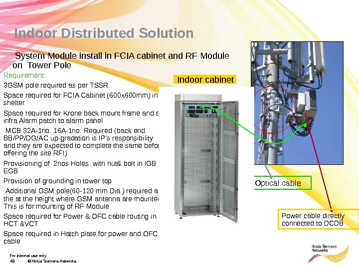
For internal use only 48 © Nokia Siemens Networks Indoor Distributed Solution Optical cable. Requirement: 3 GSM pole required as per TSSR Space required for FCIA Cabinet (600 x 600 mm) in shelter Space required for Krone back mount frame and all infra Alarm patch to alarm panel MCB 32 A-1 no. 16 A-1 no. Required (back end BB/PP/DG/AC up-gradation is IP’s responsibility and they are expected to complete the same before offering the site RFI) Provisioning of 2 nos Holes with nut& bolt in IGB & EGB Provision of grounding in tower top Additional GSM pole(60 -120 mm Dia. ) required at the height where GSM antenna are mounted. This is for mounting of RF Module Space required for Power & OFC cable routing in HCT &VCT Space required in Hatch plate for power and OFC cable System Module install in FCIA cabinet and RF Module on Tower Pole Power cable directly connected to DCDBIndoor cabinet
For internal use only 49 © Nokia Siemens Networks System Module install in OD cabinet and RF Module on Tower Pole Requirement: existing OD sites-Space required on outdoor foundation for OD cabinet installation (800 x 800 mm) O/D sites-Duct or cable tray required from shelter or Power plant to existing 2 G OD BTS for laying of Power & PCM cable OD sites- EGB with 2 nos hole along with nut and bolt is required. Provision of grounding in tower top 3 GSM pole required as per TSSR Cable trey required up to OD Cabinet Provisioning of 2 nos Holes with nut& bolt in IGB & EGB 32 A-1 no. MCB required for power taping of (back end BB/PP/DG/AC up-gradation is IP’s responsibility and they are expected to complete the same before offering the site RFI) Additional pole(60 -120 mm Dia. ) required at the height GSM antenna for RF module. Space required for Power & OFC cable routing in HCT &VCT Outdoor Distributed Solution Optical cable OD cabinet RF Module Power cable directly connected to DCDB System Module
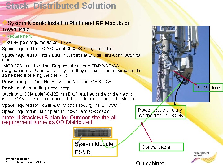
For internal use only 50 © Nokia Siemens Networks System Module install in Plinth and RF Module on Tower Pole Requirement: 3 GSM pole required as per TSSR Space required for FCIA Cabinet (600 x 600 mm) in shelter Space required for Krone back mount frame and all infra Alarm patch to alarm panel MCB 32 A-1 no. 16 A-1 no. Required (back end BB/PP/DG/AC up-gradation is IP’s responsibility and they are expected to complete the same before offering the site RFI) Provisioning of 2 nos Holes with nut& bolt in IGB & EGB Provision of grounding in tower top Additional GSM pole(60 -120 mm Dia. ) required at the height where GSM antenna are mounted. This is for mounting of RF Module Space required for Power & OFC cable routing in HCT &VCT Space required in Hatch plate for power and OFC cable Note: If Stack BTS plan for Outdoor site the all requirement same as OD Distributed Stack Distributed Solution Optical cable OD cabinet RF Module Power cable directly connected to DCDB System Module ESM
For internal use only 51 © Nokia Siemens Networks. Pole Distributed Solution System Module outside shelter or Tower bottom leg and RF Module install on tower pole Requirement: O/D sites-Duct or cable tray required from shelter or Power plant to existing 2 G OD BTS for laying of Power & PCM cable Space required for Korne back mount frame and all infra Alarm patch to alarm panel 3 GSM pole required as per TSSR` MCB 32 A-1 no. Required (back end BB/PP/DG/AC up-gradation is IP’s responsibility and they are expected to complete the same before offering the site RFI) Provisioning of 2 nos Holes with nut& bolt in IGB & EGB 2 nos Additional pole(60 -120 mm Dia. ) required at the height GSM antenna dor RF module another for System module bottem of tower leg RF Module Fiber, DC System module
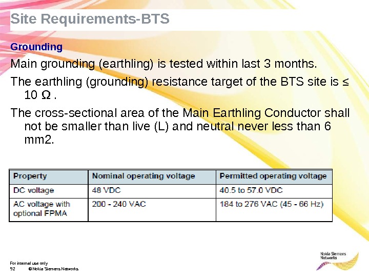
For internal use only 52 © Nokia Siemens Networks. Site Requirements-BTS Grounding Main grounding (earthling) is tested within last 3 months. The earthling (grounding) resistance target of the BTS site is ≤ 10 Ω. The cross-sectional area of the Main Earthling Conductor shall not be smaller than live (L) and neutral never less than 6 mm 2. Power
Thanks…………………