
Structural Analysis of Trusses – Method of Joints


- Размер: 3.8 Mегабайта
- Количество слайдов: 61
Описание презентации Structural Analysis of Trusses – Method of Joints по слайдам
Structural Analysis of Trusses – Method of Joints
2 Simple Trusses
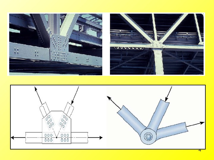
3 Truss • Definition: A truss is a structure composed of slender members joined together at their end points. The members are usually made of wood or metal • Steel trusses: Joints are usually formed by bolting or welding the members to a common plate, called a gusset plate, or simply passing a large bolt through each member.
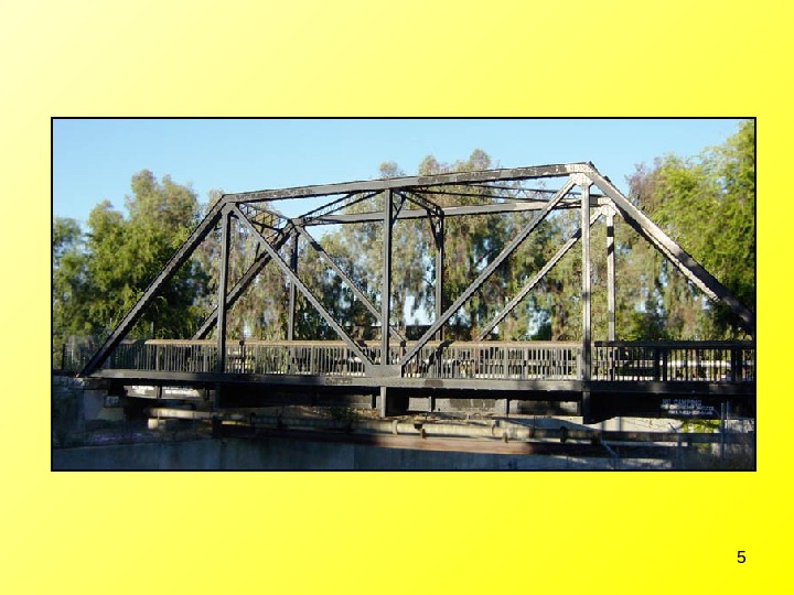
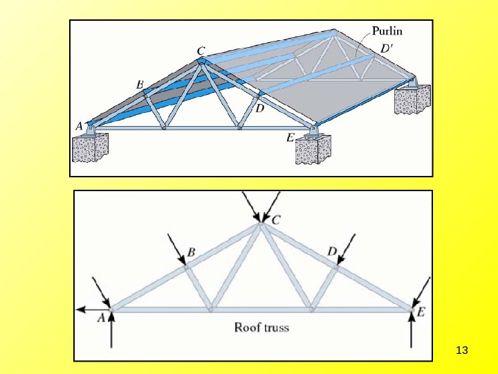
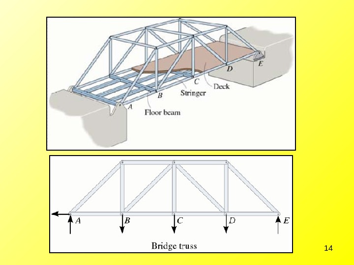
12 Planar Trusses • What we will encounter most frequently is planar truss structure. • Planar truss structures are structures which can be assumed to lie in a single plane and are often used to support roof and bridges.
15 Assumptions for Design • To design truss structure and its connections, it is first necessary to determine force in each member. • Newton’s First and Third Law will be used to solve the equilibrium equations.
16 • General assumptions concerning truss structures are: 1. All loadings are applied at the joints 2. The weights of the members are neglected. 3. All members are two force members 4. The members are joined together by smooth pins. • Note: 1. To prevent collapse, the framework of a truss must be rigid 2. The simplest framework which is rigid and stable is a triangle. 3. Therefore, a triangle is the building block of all truss structures.
17 The Method of Joints • It is important to know that for equilibrium of forces, the sufficient condition is External Force = Internal Force • External force: reaction forces, applied forces • Internal force: tension/compression force set up in the member
18 • To analyze a truss structure using method of joint, these steps are useful: 1. Draw the free-body diagram of a joint having at least one known force and at most two unknown forces. 2. Orient the x- and y -axes such that the force can be resolved into their x and y components 3. Apply force equilibrium equations 4. Continue to analyze each of the other joints by repeating procedure (i) to (iii) 5. A member in compression (C) “pushes” on the joint and a member in tension (T) “pulls” on the joints. Normally, take compression as –ve and tension as +ve.
19 Note: • In the beginning of a calculation, ignore all the compression/tension sign. • Start off by simply labeling each member consistently according to the applied force (a little bit of common sense is required here). • The final calculated numerical values will tell us if we have labeled the members correctly.
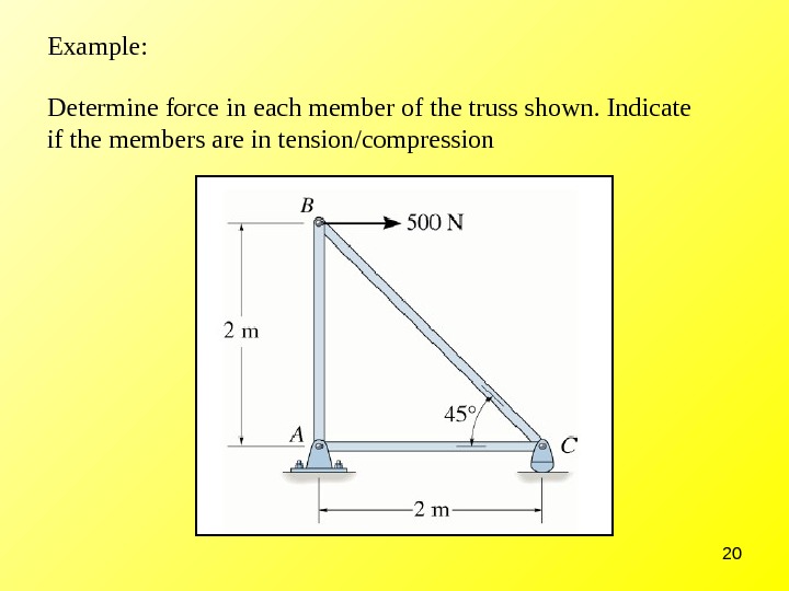
20 Example: Determine force in each member of the truss shown. Indicate if the members are in tension/compression
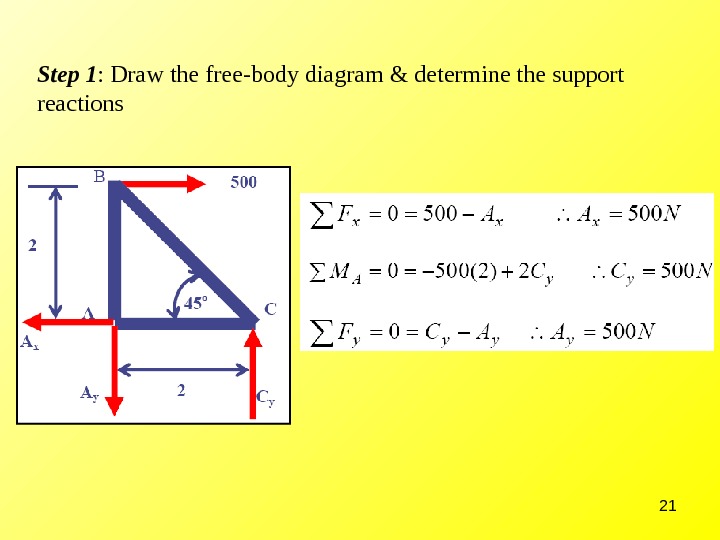
21 Step 1 : Draw the free-body diagram & determine the support reactions
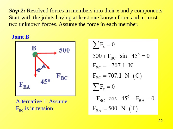
22 Step 2 : Resolved forces in members into their x and y components. Start with the joints having at least one known force and at most two unknown forces. Assume the force in each member. Joint B Alternative 1: Assume F BC is in tension
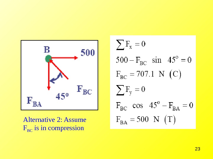
23 Alternative 2: Assume F BC is in compression
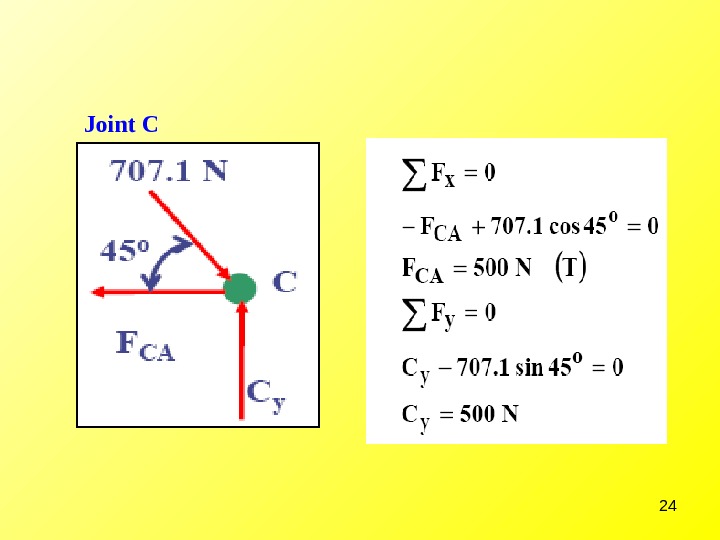
24 Joint
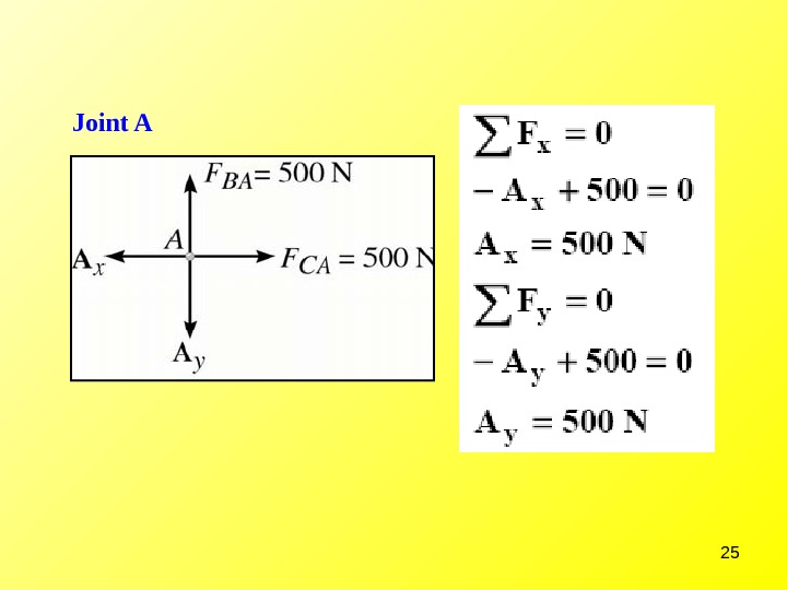
25 Joint
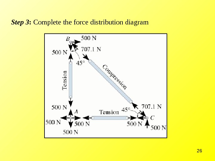
26 Step 3 : Complete the force distribution diagram
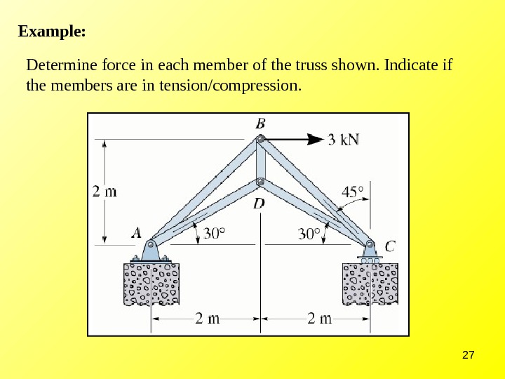
27 Example: Determine force in each member of the truss shown. Indicate if the members are in tension/compression.
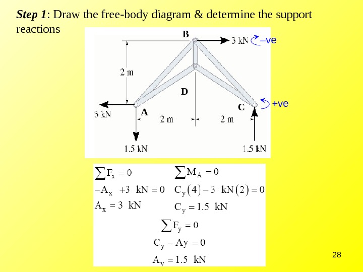
28 Step 1 : Draw the free-body diagram & determine the support reactions A CB D – ve +ve
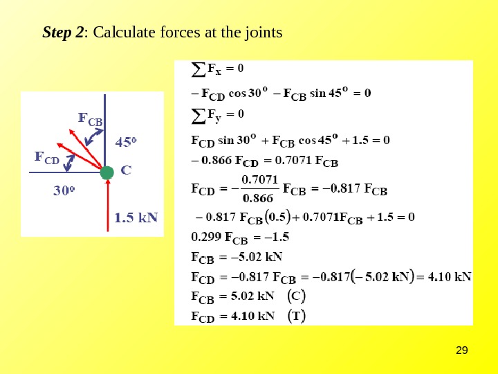
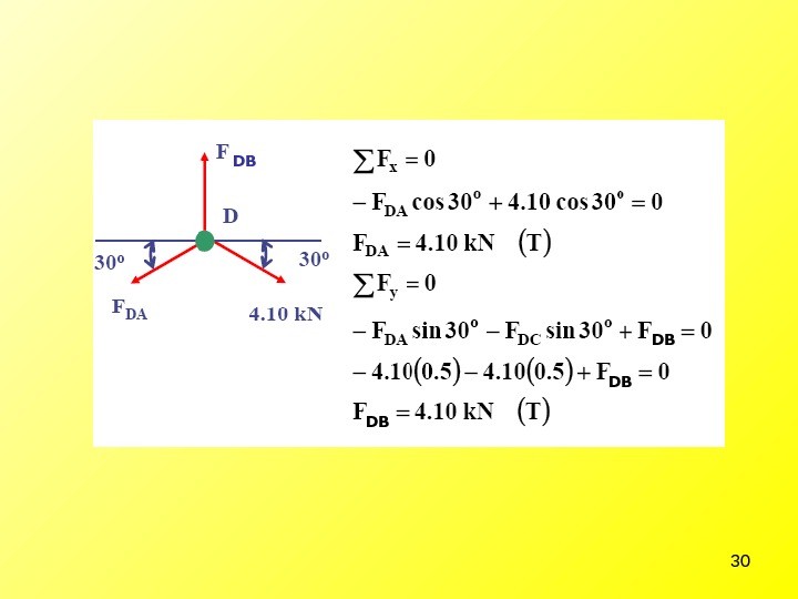
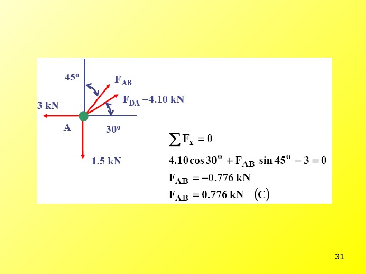
29 Step 2 : Calculate forces at the joints
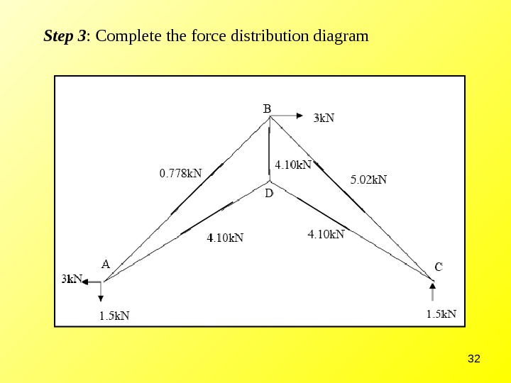
32 Step 3 : Complete the force distribution diagram
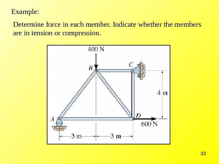
33 Determine force in each member. Indicate whether the members are in tension or compression. Example:
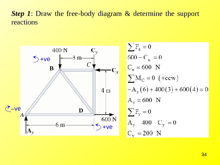
34 Step 1 : Draw the free-body diagram & determine the support reactions – ve +ve B D +ve
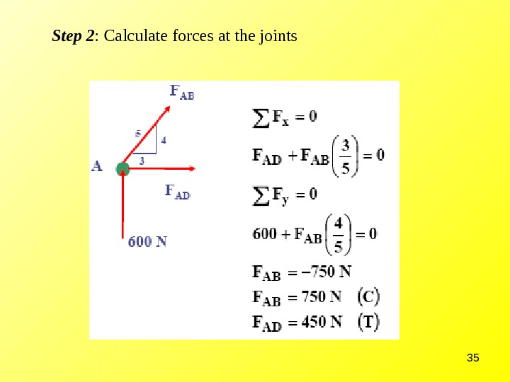
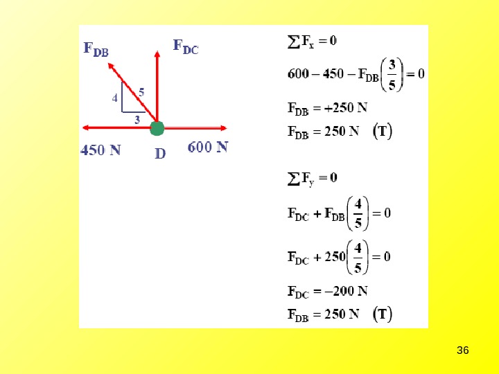
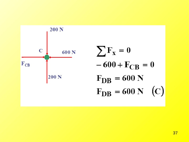
35 Step 2 : Calculate forces at the joints
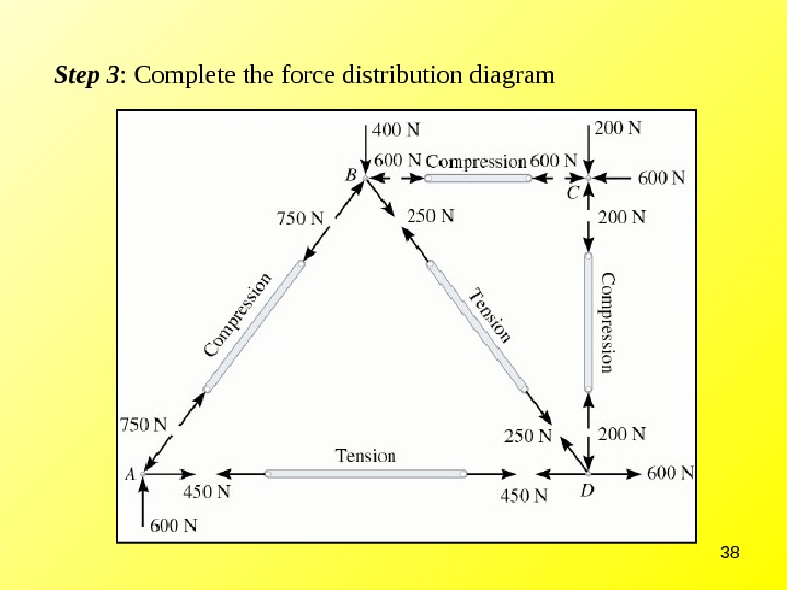
38 Step 3 : Complete the force distribution diagram
Structural Analysis of Trusses – Method of Sections
40 Zero-Force Members • Our analysis can be greatly simplified if one can identify those members that support no loads. We call these zero-force members. • These members can used to increase the stability of the truss during construction and to provide support if the applied loading is change.
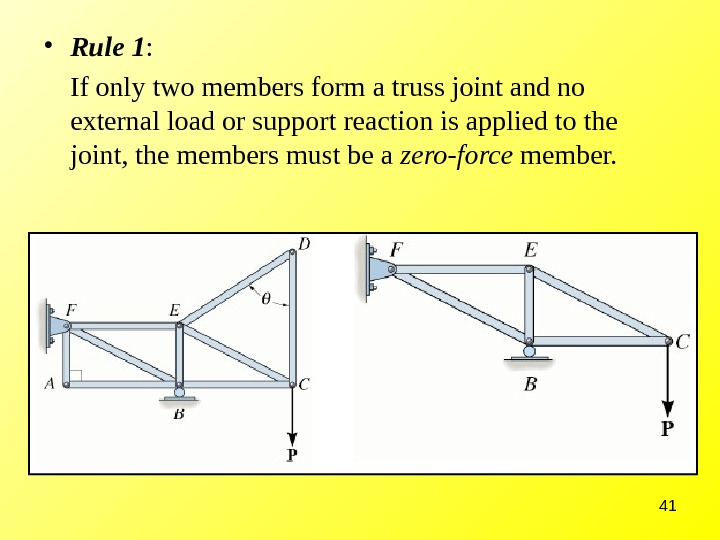
41 • Rule 1 : If only two members form a truss joint and no external load or support reaction is applied to the joint, the members must be a zero-force member.
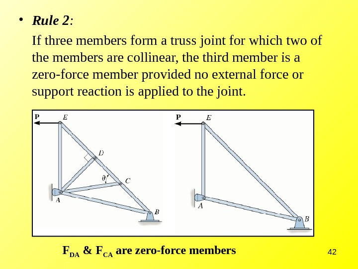
42 • Rule 2 : If three members form a truss joint for which two of the members are collinear, the third member is a zero-force member provided no external force or support reaction is applied to the joint. F DA & F CA are zero-force members
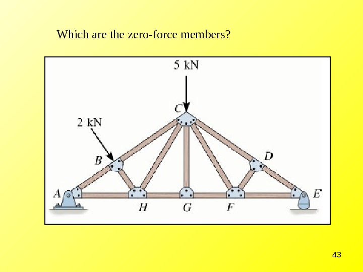
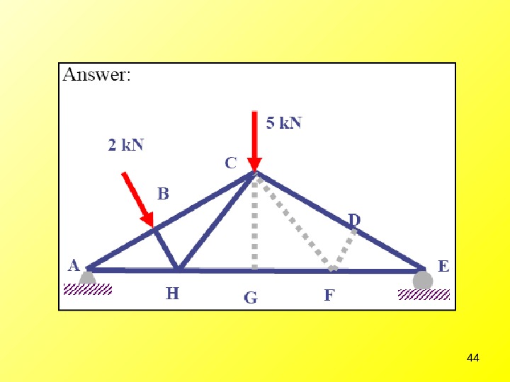
43 Which are the zero-force members?
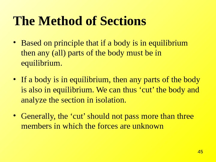
45 The Method of Sections • Based on principle that if a body is in equilibrium then any (all) parts of the body must be in equilibrium. • If a body is in equilibrium, then any parts of the body is also in equilibrium. We can thus ‘cut’ the body and analyze the section in isolation. • Generally, the ‘cut’ should not pass more than three members in which the forces are unknown
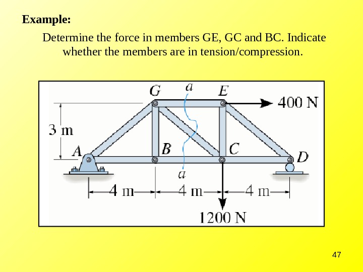
47 Determine the force in members GE, GC and BC. Indicate whether the members are in tension/compression. Example:
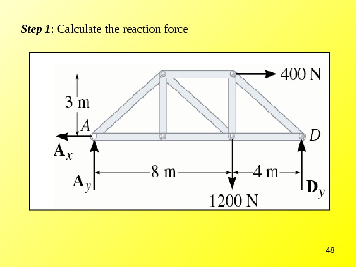
48 Step 1 : Calculate the reaction force
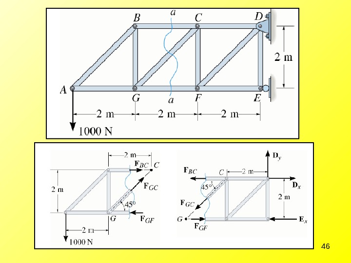
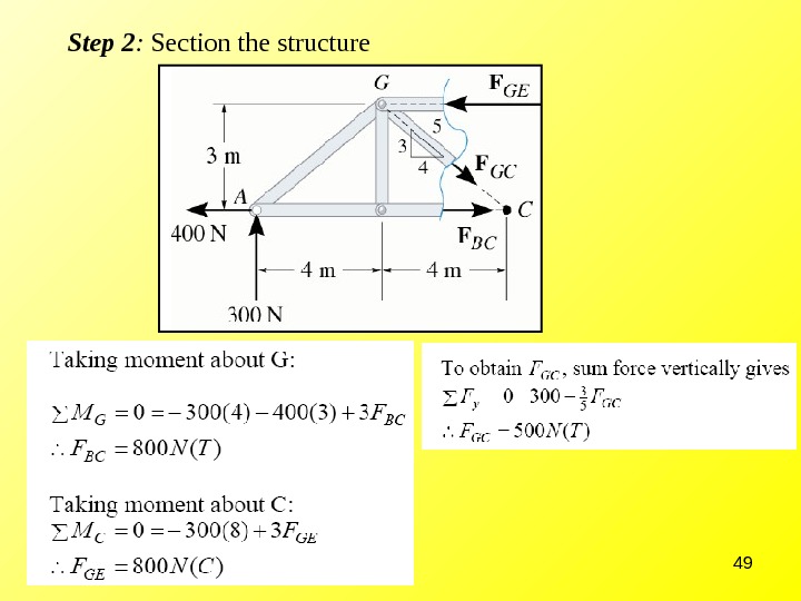
49 Step 2 : Section the structure
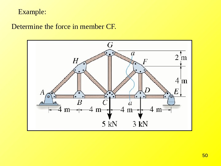
50 Example: Determine the force in member CF.
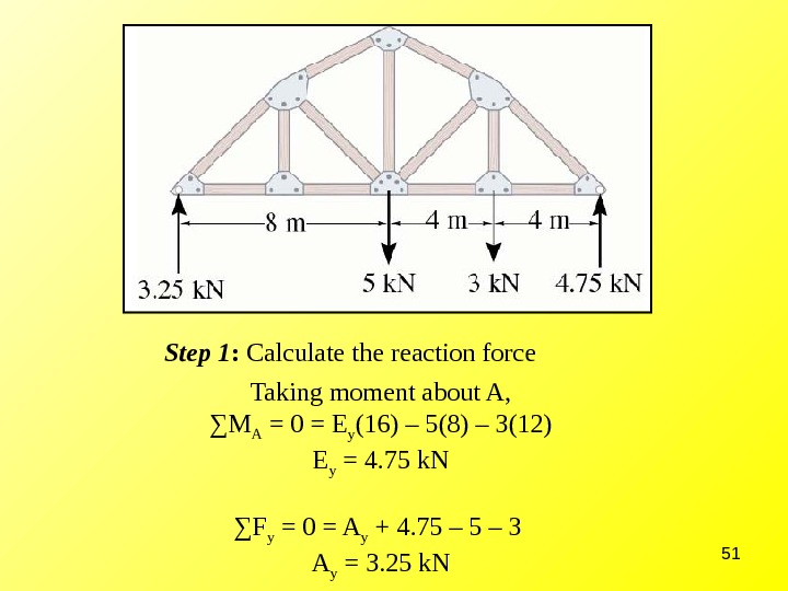
51 Taking moment about A, ∑ M A = 0 = E y (16) – 5(8) – 3(12) E y = 4. 75 k. N ∑ F y = 0 = A y + 4. 75 – 3 A y = 3. 25 k. NStep 1 : Calculate the reaction force
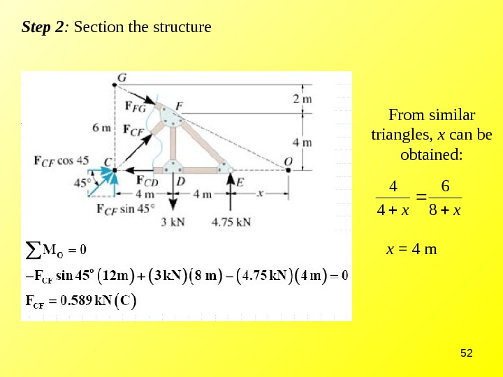
52 Step 2 : Section the structure From similar triangles, x can be obtained: xx 8 6 4 4 x = 4 m
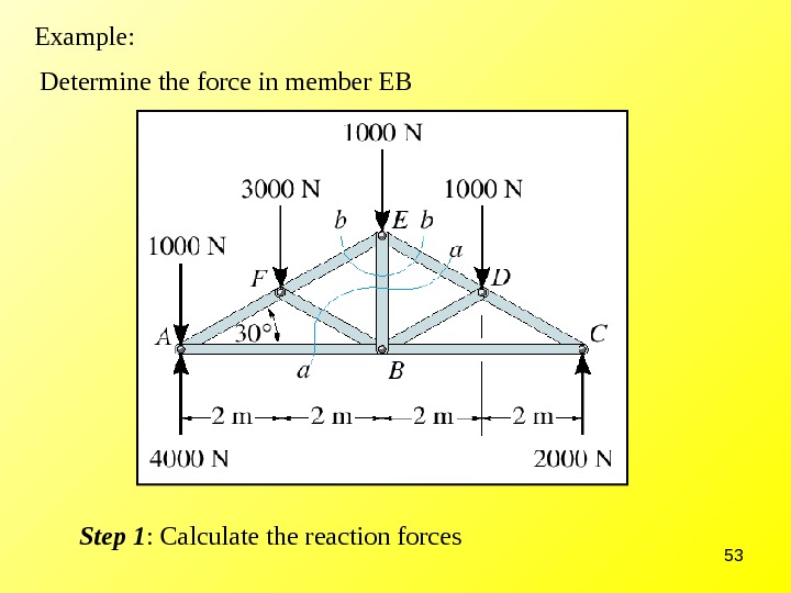
53 Example: Determine the force in member EB Step 1 : Calculate the reaction forces
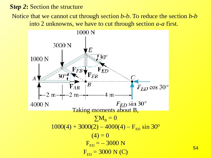
54 Step 2 : Section the structure Notice that we cannot cut through section b-b. To reduce the section b-b into 2 unknowns, we have to cut through section a-a first. Taking moments about B, ∑ M B = 0 1000(4) + 3000(2) – 4000(4) – F ED sin 30° (4) = 0 F ED = – 3000 N F ED = 3000 N (C)
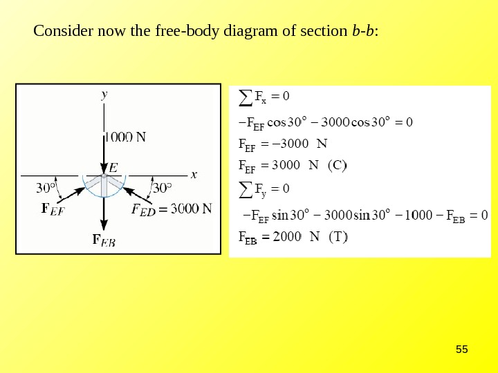
55 Consider now the free-body diagram of section b-b :
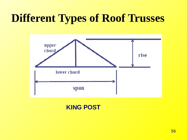
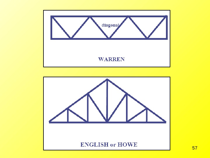
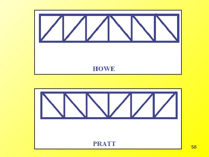
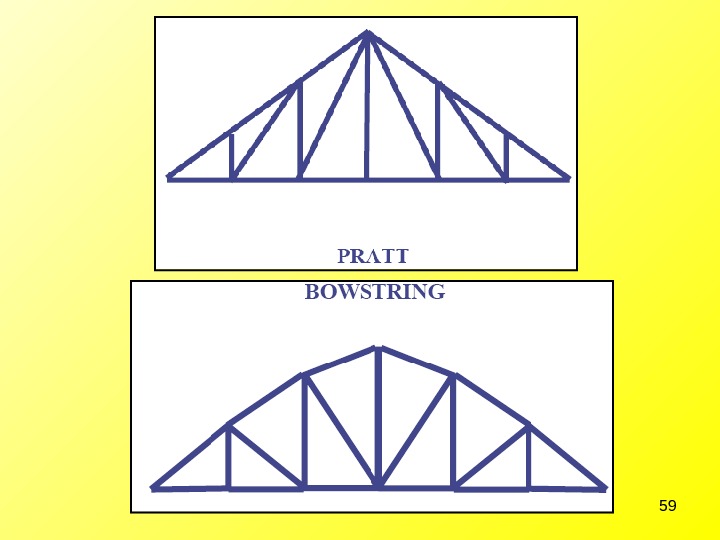
56 Different Types of Roof Trusses KING POST
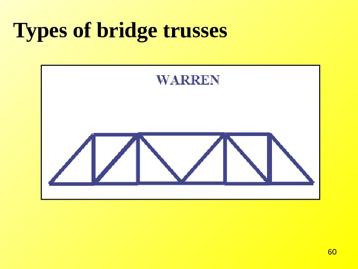
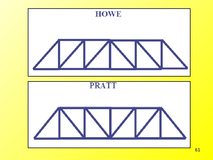
60 Types of bridge trusses