

6829576747b33e6365d6c606b7f1ba31.ppt
- Количество слайдов: 41
 STRATA MONITORING INSTRUMENTS Pawan Dhanuka
 Introduction We are pleased to introduce ourselves as a leading manufacturer of safety and support items for the past 27 years. We are a regular supplier of various safety items since a very long time. We offer a variety of instruments for your Strata Monitoring needs.
 STRATA CONTROL INSTRUMENTATION Permanent Roadways Monitoring Active Working Area monitoring Identification of locations Selection of Locations Marking over Instrumentation Plan Instrumentation Display Documentation Analysis Corrective Measure Apprehension of load in roof Apprehension of roof failure Proper support resistance / Immediate corrective action
 PARAMETERS TO BE MONITORED n n n Dilation & bed separation with in roof. Convergence of roof. Stress developed on pillars / ribs. Strain developed / Axial loading on roof bolts. Load on supports Axial Load
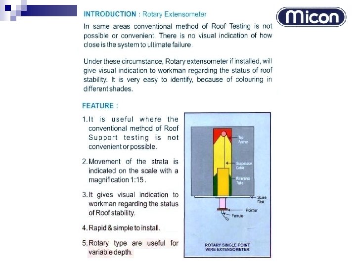
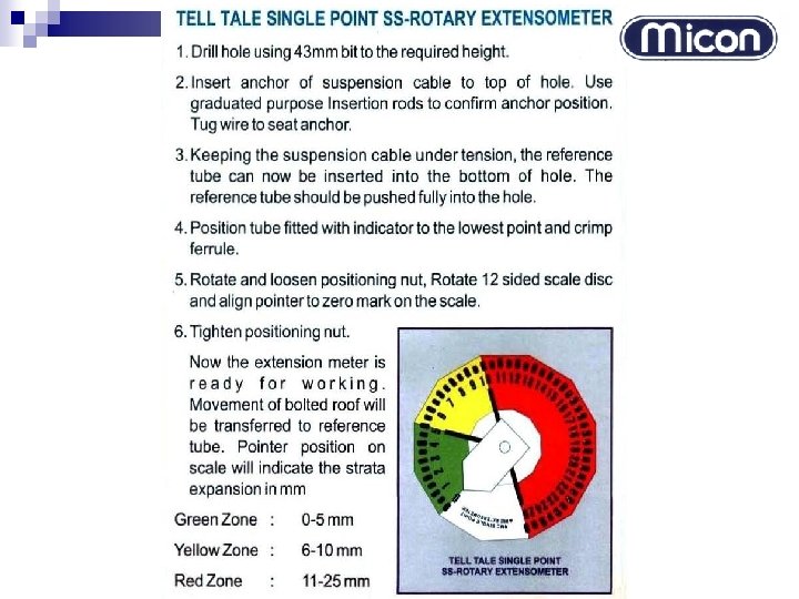
 DILATION This is the gap generated between two consecutive stratum due to bed separation. This can be monitored by installation and function of: n Tell Tale
") EXTENSOMETER (TELL TALE, 2 point)
EXTENSOMETER (TELL TALE, 2 point)
") EXTENSOMETER (TELL TALE)
EXTENSOMETER (TELL TALE)
 TELL TALE – 4 POINTS
 AUTO WARNING TELL TALE Introduction Intrinsically safe Auto-Warning Telltale has been designed to provide a highly visible immediate warning of excessive movement occurring in a rockbolted tunnel or mine roadway, over and above that provided by the coloured bands on a standard telltale. This can be of particular value in dynamic mining situations, such as pillar extraction operations, where the workmen and equipment are operating close to a developing goaf.
 AUTO WARNING TELL TALE Production Description The Auto-Warning Telltale has bright Light Emitting b Bulbs fitted to the underside of the drip tray. The LEDs are configured to begin to flash if the movement on the visual indicator shows total roof dilation exceeding 5 mm (or other factory set trigger value). The LEDs will continue to flash whilst the indicator shows more than the trigger level, until the battery is exhausted (at least 3 days). However the LED will stop flashing if the indicator movement reduces back to below the trigger level. This ensures that it is not inadvertently triggered during transportation, installation or cleaning. Safety The Auto-Warning Telltale has been designed and approved to be intrinsically safe to both IECEx and ATEX standards.
 CONVERGENCE This is the closure of vertical gap between roof & floor, created either due to down ward movement of roof or up ward bulging of floor or both. This is a phenomena, generally occurs during Dynamic Loading. This is an indicative parameter deciding extent of advance support during extraction. This can be measured by installation and analysis of out comes of n n Telescopic & Suspension Convergence Indicators Convergence Recorder (Mechanical Chart Drive)
 TELESCOPIC CONVERGENCE INDICATOR Construction It consists of an outer tube inside which a close fitting rod slides. On this rod a scale is graduated with 1 mm least count. Observation To, measure the convergence between roof and floor, stations are fixed by means of grouted stations: ' Instrument is fixed between these two stations and reading is taken against outer tube up to an accuracy of 1 mm. One instrument is sufficient for several stations and there is no like hood of stations being disturbed by movement of machinery etc.
 LIGHT WEIGHT TELESCOPIC CONVERGENCE INDICATOR Construction MICON’S Light Weight Telescopic Convergence Indicator consists of an outer & inner Light weight and durable fiber body tube. On the inner tube a scale is present with 1 mm least count, the same is highlighted by reflecting tape to enable easy viewing in underground low light surroundings. The advantages of Light Weight Indicator over the conventional Indicator are as follows: i) Easy to Use and Transport ii) Presence of Reflecting Tape Enable easy viewing in Low Light Conditions iii) Non Rusting Fibre Tubes iv) Less prone to Pilferage as opposed to Brass.
 SUSPENSION CONVERGENCE INDICATOR Construction Consists of an outer non-rusting tube, on this tube a scale is graduated with 1 mm least count by etching operation. The scale does not fade because of etching. It also consists of two pins 'A' & 'B' Pin 'A' is fixed to outer tube 'D' and other pin 'B' on movable rod 'C', Points between roof and floor is fixed by grouted stations. Observation Initial setting of instrument is done by chain through turn-buckle Distance between two pins is measured by vernier calliper to an accuracy of 0. 02 mm. The instrument is simple and retains its original position even when disturbed because of high tension spring.
 INSTALLATION n The base end of the outer pipe is fixed to the floor of the gallery by some means at a strategic place and the top end of the inner telescopic pipe is fixed to any point in the roof, keeping the instrument perfectly vertical. n Any convergence between roof and floor, causes relative movement of pipes, giving direct reading from the graduations of inner pipe. DOCUMENTATION Date Shift Place Time Cum. Rate of Reading Change / (mm) Shift (mm/Shift) Working position (m) Remarks
 DIRECT-RECORDING CONVERGENCE METER MICON’ Convergence Meter has been developed for continuously recording convergence in mines. Direct plots of convergence versus time are obtained over a range. The Convergence Meter Consists basically of a clockwork driver, a chart paper drum and a spring loaded scriber arm mounted on telescopic tubes. In use the tubes are coupled between two pins located on roof and floor. As the roof & floor converge the tubes telescope into each other causing the scriber arm to trace a varying path over the chart paper mounted on the slowly rotating drum. On removal the chart is a permanent direct record of convergence plotted against time. The mechanisms are totally enclosed in a transparent housing to exclude dust and moisture.
 DIRECT-RECORDING CONVERGENCE METER SECIFICATIONS: Chart Speed – 1 Rev. / 1 day & 7 day (or an option of Dual Speed drive, simple switch for alternating between 1 and 7 days) Convergence Range – 75 mm/100 mm/150 mm/250 mm Mechanical Clock- Spring Work Drive. Shock-resistant and antimagnetic Swiss anchor escapement Stainless steel winding spring , pinions and shaft Accuracy : +/- 5 sec/24 hour Stainless Steel Telescopic Tubes. . Rugged construction. Direct record of convergence versus time. Automatic continuous – recording ORDERING INSTRUCTIONS: Specify: 1) Maximum seam height 2) Convergence Range 3) Chart Speed – Daily /Weekly/Dual Speed (Option of Daily and Weekly Rotation in a single Clock)
 STRESS Stresses are the ground pressure associated with every location in the stratum. Principally these originate from the mechanism of dual equilibrium of forces due to spinning actions of the Earth around the Sun and around its own axis. Knowledge of magnitude and direction is important for safe strata management.
 TYPES OF STRESS n n In situ stress Induced Stress DIRECTION OF STRESS • Horizontal Stress • Vertical Stress
 STESS METER/CELL
 STESS METER/CELL Vibrating Wire Borehole Stress meters are designed to measure stress changes in rock and can be installed in boreholes up to 100 feet deep. The Stress meter consists of a high strength steel proving ring wedged tightly across one diameter inside a borehole and a vibrating wire tensioned across the other diameter inside the stress meter. Changes in rock stress cause a related change in the resonant frequency of vibration of the tensioned wire providing output which is read by the Geokon Readout Box. (Intrinsically safe)
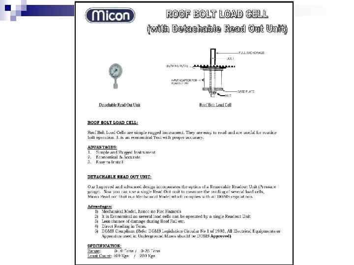
 LOAD ON SUPPORTS This is the release of vertical stress over support system due to Loading effects of super incumbent, both In situ and Dynamic loading. It can be monitored by; ¨ ¨ Hydraulic Load Cell for Roof Bolts with separate Read out Unit Hydraulic Load Cell for Roof Bolts Hydraulic Load Cell for Pit Props Intrinsically Safe Vibrating wire Load Cell.
 LOAD CELLS § We would also like to point out that as per our knowledge most users are using electronic vibrating wire type (battery operated) load cells with digital readout unit, which are not Intrinsically safe & DGMS APPORVED (Refer DGMS Legislation Circular No 1 of 1993).
 Hydraulic Load Cell for Roof Bolts with separate Mechanical Read out Unit § Our New and Improved design incorporates the option of a Removable Readout Unit (Pressure gauge). Now you can use a single Read Out unit to measure the reading of several load cells, Micon Read out Unit is a Mechanical Model which complies with all DGMS regulations. § Previously these Load cells came with a fixed Load/pressure gauge and hence were higher in cost and also in most cases the non detachable readout units were damaged during roof falls etc. Therefore in order to reduce cost and improve the life of the product we have developed this model.

 Vibrating Wire Load Cell
 PRINCIPLE OF OPERATION n It is potentiometer / resistance sensor based and is designed to measure load on support system at accessible and inaccessible locations. n This can be used with both positive and non positive support system. n Load on support system in turn on the Load Cell causes change in frequency / resistance, which can be inculcated from a safe distance through wires and Read out Units and subsequent conversion to the required units.
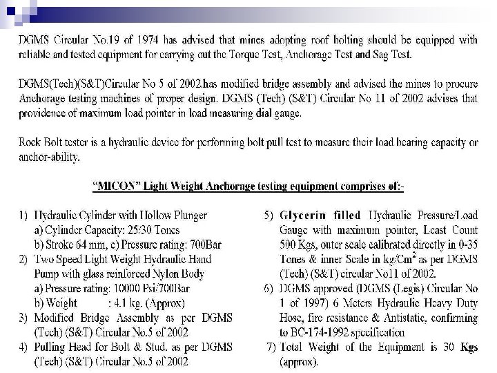
 Light Weight Anchorage Testing Machine
 SHORT ENCAPSULATION PULL TEST EQUIPMENT
 SHORT ENCAPSULATION PULL TEST EQUIPMENT As per DGMS Guidelines, it is advised to carry out Short encapsulation pull testing of every batch of resin capsule. (Ref: DGMS/S&T/Tech Cir (approval) No 3 of 2010) Short encapsulation pull testing is essentially to verify rock-bolt system performance. Micon supplies all the equipment needed to undertake short encapsulation pull testing on site in mining and tunneling environments. • Calibrated hollow ram, hand pump and pressure gauge • Face plate, bearing nut & pull bar • Monopod and dial gauge • Steel carrying case
 AXIAL LOAD These are the point loads acting on a vertical plane with in the crust, originated due to mining induced effects. This phenomenon is very useful in deciding bolting length and deciding strength of reinforcement in roof mass. STRAIN GAUGE ROCK BOLT
 MOVEMENT ALONG JOINTS, SLIPS & CRACKS Identification and inculcation of even slightest relative movement along slips and joints is important for prevention of strata failure at such places. Instruments available for identification and inculcation of relative movement along slips / joints are; n n Crack Meter Joint Meter
 CRACK METER PRINCIPLE OF OPERATION -It is designed for measuring movements across surface cracks or joints preferably in the roof. It can be used at both accessible / inaccessible locations. -It consists of an electrical transducer coil and two anchors. These anchors are pre fixed in the roof. -Any change in the distance across the two anchors, changes the tension corresponding to change in electrical signal, which gives the reading in mm through ROU.
 JOINT METER
 SCCL ITEM CODE NO. § § § Load Cell Hydraulic, Material Code No : 4439153847 Tell Tale (2 Point, 1 Meter), Material Code No : 4439154591 Tell Tale (2 Point, 5 Meter), Material Code No : 4439154608 Tell Tale (4 Point), Material Code No : 4439153800 Convergence Indicator, Material Code No : 4439153847 Vibrating Wire Stress Cell, Material Code No. : 4439154580
 THANK YOU