

0f8f4b75b3233be690f48178de81e6d6.ppt
- Количество слайдов: 27
 STF Plan & Schedule H. Hayano, KEK
 Superconducting RF Test Facility Comprehensive Test Facility dedicated to ILC SC-RF R&D (expandable to FEL, ERL) for superconducting cavity; fabrication, process, installation, vertical test / horizontal test, system test with beam for cryomodule; cavity installation, cryostat operation, heat cycle test, input coupler R&D, tuner mechanism R&D for power source; modulator development, klystron development, WG components for He plant; High efficiency cryogenic system for beam instrumentation; ILC beam generation, BPM, HOM, Low-Level RF control
 Issues of existing ILC-SC engineering 1. Reliability of cavity gradient >35 MV/m 2. Complexity and cost of Input coupler 3. Rigidity of cavity-jacket relating to Lorentz detuning 4. Reliability of tuner mechanism, Reliability of Piezo in cold 5. Cavity alignment after cooling down 6. Cost optimization of RF Waveguide System 7. Cost optimization of cryomodule 1. … 2. etc.
 Purpose of Test Facility in KEK STF Phase 1 1. To provide stable and reliable gradient 35 MV/m with reasonable yield rate. 2. To provide reliability data of 45 MV/m gradient. 3. To provide a solution to issues of existing ILC-SC engineering using KEK SC engineering experience. 4. Construct cavity treatment facility in KEK. 1. STF Phase 2 2. 1. Construct assembling facility of ILC cryomodule. 2. Assemble ILC cryomodule. 3. Construct cryomodule test facility. Both 1. To be a base facility for international collaboration. • To provide a basis of realistic cost estimation and mass production. 2. To promote LC researchers and industries for production of SC-Cavities and cryomodules. 3. To give an opportunity to train up young researchers and students.
 KEK SC RF technology and many expert: TRISTAN SC cavity") Test Facility Background 1) KEK SC RF technology and many expert: TRISTAN SC cavity (500 MHz, CW) 1980’s - 1990’s KEK-B SC cavity (500 MHz, CW) 1990’s - …. KEK L-band R&D (1. 3 GHz, 972 MHz, CW) 1990’s - …. J-PARC SC cavity R&D (972 MHz, pulse) 2000’s - …. 2) Existing Test Facility Infrastructure: 1. Cavity treatment, vertical test stand at KEK L-band R&D Stand 2. Spare 600 W He Plant at AR-East hall (TRISTAN) & KEK-B Cryogenic System Operation Team 3. Proton Linac Building for J-PARC ( DTL accelerator system will be moved and installed in J-PARC, Tokai by August 2005. Then, air conditioned building & Tunnel with cooling water is available. )
Test Facility Background 1) KEK SC RF technology and many expert: TRISTAN SC cavity (500 MHz, CW) 1980’s - 1990’s KEK-B SC cavity (500 MHz, CW) 1990’s - …. KEK L-band R&D (1. 3 GHz, 972 MHz, CW) 1990’s - …. J-PARC SC cavity R&D (972 MHz, pulse) 2000’s - …. 2) Existing Test Facility Infrastructure: 1. Cavity treatment, vertical test stand at KEK L-band R&D Stand 2. Spare 600 W He Plant at AR-East hall (TRISTAN) & KEK-B Cryogenic System Operation Team 3. Proton Linac Building for J-PARC ( DTL accelerator system will be moved and installed in J-PARC, Tokai by August 2005. Then, air conditioned building & Tunnel with cooling water is available. )
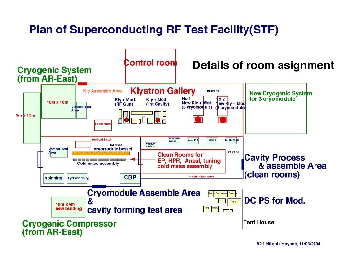
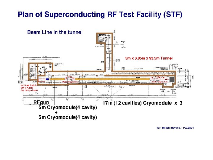
 60 m x 30 m building: Klystron Gallery (with extendable") Proton Linac Building 1) 60 m x 30 m building: Klystron Gallery (with extendable space) Cavity installation room magnet power supply room (with extendable space) Control room (with extendable space) Cooling water facility AC power yard external Tent House 2) 5 m x 3. 85 m x 93. 5 m tunnel: Access hatch only 2 m x 4. 5 m with elevator (with extendable space)
Proton Linac Building 1) 60 m x 30 m building: Klystron Gallery (with extendable space) Cavity installation room magnet power supply room (with extendable space) Control room (with extendable space) Cooling water facility AC power yard external Tent House 2) 5 m x 3. 85 m x 93. 5 m tunnel: Access hatch only 2 m x 4. 5 m with elevator (with extendable space)
 Location of Test Facilities Proton Linac Building KEK-B He Plant Control Center ATF L-band R&D Stand #4 building
 Proton Linac Building outside
 DTL assembling room Q-magnet P. S. room
 Klystron Gallery
") Underground Tunnel (DTL)
Underground Tunnel (DTL)
 Proton Linac Building Plane View
 Available Devices for STF He plant : TCF 200 spare plant DC gun : from ERL development (now under commissioning) Klystron Modulator, Waveguide, RF components : kept in Tent House, from PNC Beam dump : kept in ATF space, from PNC Concrete shield for dump : kept in Proton Linac Building
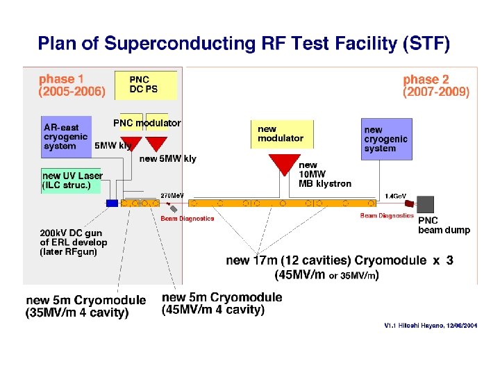
: 1. 3 GHz 1. 5 cell") STF Test Accelerator ---- phase 1 ------------(RF gun): 1. 3 GHz 1. 5 cell copper cavity 42 MV/m, 3. 2 n. C/bunch 3. 2 MW, 1 ms klystron, 5 Hz DC gun : 200 k. V Cs. Te photocathode for quick start UV(262 nm) Laser (337 ns spacing, 2820 bunches) Capture cavity ( & Horizontal Test stand) : 4 x 9 cell TESLA SC cavity (5 m cryomodule), 35 MV/m 4 x 9 cell LL SC cavity (5 m cryomodule), 45 MV/m 4 x 350 k. W + 4 x 450 k. W = 3. 2 MW, 1. 5 ms klystron, 5 Hz Vertical Test Stand : deep enough for superstructure cavity Coupler Test Stand : 1 MW, 1. 5 ms klystron, 5 Hz (switch use between horizontal stand) ---- phase 2 ------------Accelerating Unit : 3 set of 17 m full-size (12 cavities) cryomodule 2 x 10 MW, 1. 5 ms klystron, 5 Hz
STF Test Accelerator ---- phase 1 ------------(RF gun): 1. 3 GHz 1. 5 cell copper cavity 42 MV/m, 3. 2 n. C/bunch 3. 2 MW, 1 ms klystron, 5 Hz DC gun : 200 k. V Cs. Te photocathode for quick start UV(262 nm) Laser (337 ns spacing, 2820 bunches) Capture cavity ( & Horizontal Test stand) : 4 x 9 cell TESLA SC cavity (5 m cryomodule), 35 MV/m 4 x 9 cell LL SC cavity (5 m cryomodule), 45 MV/m 4 x 350 k. W + 4 x 450 k. W = 3. 2 MW, 1. 5 ms klystron, 5 Hz Vertical Test Stand : deep enough for superstructure cavity Coupler Test Stand : 1 MW, 1. 5 ms klystron, 5 Hz (switch use between horizontal stand) ---- phase 2 ------------Accelerating Unit : 3 set of 17 m full-size (12 cavities) cryomodule 2 x 10 MW, 1. 5 ms klystron, 5 Hz
 Accelerator Laboratory Concept of test facility for quick and inexpensive start Making use of power supply and waveguide component moved from PNC (Power Reactor and Nuclear Fuel Corp). Power supply has 3 modes; (1)Short pulse (100µs), (2)long pulse (4 ms) and (3)CW for the modulating anode type klystron. For mode(2), possible klystron is modulating anode type TH 2115 (Thales). About 2 MW output is possible for this case. 5-10 MW Reform to (PT+Bouncer) allows to use TH 2104 C. Photo of Modulator in PNC Block diagram of PNC modulator SF 041104
 Conceptual design of 4 cavity cryomodule TESLA design Same inner structure with TESLA design, Extendable to long cryomodule, R&D on Input coupler improvement, Cavity rigidity improvement, Tuner mechanism improvement, Alignment accuracy improvement, Maintainability improvement, Cost reduction, Industrialization …….
 2.") Improvement Example 1. Input coupler improvement for simple & cost reduction (no tuning) 2. cavity and He jacket rigidity improvement for small Lorentz detuning 3. Simplification of Tuner mechanism, exchangeability of Piezo Element
Improvement Example 1. Input coupler improvement for simple & cost reduction (no tuning) 2. cavity and He jacket rigidity improvement for small Lorentz detuning 3. Simplification of Tuner mechanism, exchangeability of Piezo Element
 Cryogenic System Plan similar to TESLA cryomodule
 Conceptual design of cryomodule connection Valve Box Phase 1 Weld connection 35 MV/m TESLA design cavities 45 MV/m Low-loss cavities Become to 8 cavities in one cryostat Like TTF cryomodule
 High Power RF (inc.") Man-power for STF Cryogenic plant : Team K. Hosoyama (7) High Power RF (inc. LLRF) : Team S. Fukuda(11) Cryomodule (exc. Cavity) : Team S. Noguchi(3) & Team K. Tsuchiya(2) SC-Cavity : Team K. Saito(14) Electron Gun : Team S. Osawa(4) Control & Operation : Team ATF(9) & Team XTF(5) Surface Process Facility : Team K. Saito(14) & Team K. Ueno (Mec. Eng. Center) Total 52 (excl. double count), ~23 FTE
Man-power for STF Cryogenic plant : Team K. Hosoyama (7) High Power RF (inc. LLRF) : Team S. Fukuda(11) Cryomodule (exc. Cavity) : Team S. Noguchi(3) & Team K. Tsuchiya(2) SC-Cavity : Team K. Saito(14) Electron Gun : Team S. Osawa(4) Control & Operation : Team ATF(9) & Team XTF(5) Surface Process Facility : Team K. Saito(14) & Team K. Ueno (Mec. Eng. Center) Total 52 (excl. double count), ~23 FTE
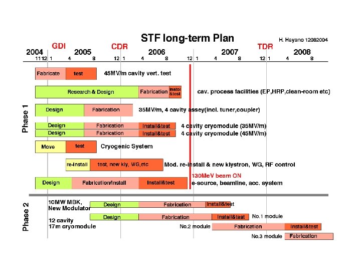
 STF phase 1 start-up 2004 - 2005 Cryogenic plant movement: March 2005 4 cavity Cryomodule : start design Cavities: 45 MV/m cavity fabrication and test continue 35 MV/m cavity fabrication in 2005 Cavity treatment facility : start research and design, equip in 2006 Power source : start re-building modulator, buy 5 MW klystron DC gun: move to Tunnel in August 2005, Laser development in 2006 ( start RF gun cavity design ) Phase 1 beam line: equip in 2006, RF-test & beam-test in Dec. 2006
 STF phase 2 1 full unit of ILC Main Linac Multi-beam Klystron 17 m cryomodule
 Collaboration Plan with Overseas Asia: mainly on design works, people, magnets, instrumentation etc. Europe: collaboration on TESLA/TTF designs and engineering information, provide SC technologies, exchange people, obtain other technologies( power source, control, beam generation, instrumentation) US: done by US-Japan collaboration mainly, provide SC technologies, exchange people, obtain other technologies( power source, control, beam generation, instrumentation) (Success of STF phase 1 is key of collaboration success)