

a4da69bbfc14083eedb68de3c780a6f7.ppt
- Количество слайдов: 36
 State of Structural Health Monitoring Erdal Safak and Ken Hudnut USGS, Pasadena ANSS National Steering Committee November 18, 2004 Westin St. Francis Hotel, San Francisco
 ANSS Objectives • Improve the Nation’s ability to respond effectively to damaging earthquakes, reduce monetary losses, and save lives • Provide data necessary to improve structural safety and speed emergency response and recovery (so as to reduce losses) The current draft ANSS plan does not optimally achieve these stated objectives; so, an alternative approach is suggested & explained
 State of Health Monitoring of Structures Ø Damage Detection and Damage. Map Ø GPS & INS Integration Technology Ø Instrumentation Needs
 FORCE Non-linear dynamics can be detected by inertial sensors Not reliable though DISPLACEMENT D 0 = Permanent displacement Hysteretic forcedeformation DISPLACEMENT FORCE Stiffness remains about the same despite damage D 0
 Millikan Library at Caltech

") (From www. ce. caltech. edu/~jclinton/thesis. html)
(From www. ce. caltech. edu/~jclinton/thesis. html)
") (From USC Report CE 99 -02 by Trifunac et al. , 1999)
(From USC Report CE 99 -02 by Trifunac et al. , 1999)
 Big Bear – No damage 0. 75 Hz FREQ. (Hz) Northridge –") FREQ. (Hz) Big Bear – No damage 0. 75 Hz FREQ. (Hz) Northridge – Damaged 0. 50 Hz TIME (S)
FREQ. (Hz) Big Bear – No damage 0. 75 Hz FREQ. (Hz) Northridge – Damaged 0. 50 Hz TIME (S)
 AUTOMATED TAGGING AND REAL-TIME DAMAGE DISTRIBUTION MAPS Automated Tagging and Real-Time Damage Distribution Maps FRC. Multiple sensor package: • Acceleration / Velocity • Displacement (GPS) • Rotation (tilt-meter) Linear Nonlinear DIS P. Permanent displacement Pre-earthquake: Post-earthquake: ØReference static displacement ØReference static rotation ØMean and variance of dynamic characteristics ØPermanent static displacement ØPermanent static rotation ØMean and variance of dynamic characteristics During earthquake: ØChanges in dynamic characteristics ØHysteretic behavior ØDamage initiation


 State of Health Monitoring of Structures Ø Damage Detection and Damage. Map Ø GPS & INS Integration Technology Ø Instrumentation Needs
 Gyros and MEMS with GPS • Stable gyro technology is costly but MEMS-gyro and IFOG are low-cost and approaching accuracy Barbour & Schmidt, 1998
 in airborne imaging Ø GPS aircraft trajectory relative to groundbased GPS array") GPS/INS (RLG) in airborne imaging Ø GPS aircraft trajectory relative to groundbased GPS array Ø INS for aircraft attitude Ø Laser mirror and/or camera position and orientation very well known Ø New imaging capabilities (also for satellite imagery)
GPS/INS (RLG) in airborne imaging Ø GPS aircraft trajectory relative to groundbased GPS array Ø INS for aircraft attitude Ø Laser mirror and/or camera position and orientation very well known Ø New imaging capabilities (also for satellite imagery)
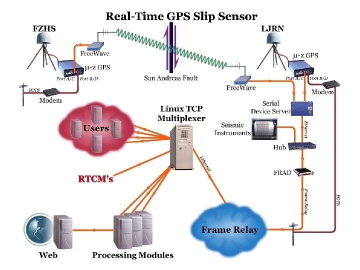
 Lone Juniper Ranch and Frazier Park High School First prototype GPS fault slip sensor; up to 10 Hz (Hudnut et al. , 2002) Spans the San Andreas fault near Gorman, California
 San Andreas fault Ø 35 mm/yr slip rate; Ø Ø Ø Big Bend compression Ø Ø Ø Ø Ø >70% of plate motion 1685, 1812, 1857 eq’s 1971 Sylmar (M 6. 7) 1994 Northridge (M 6. 7) So. Cal is now heavily ‘wired’ - need more? 150+ BB CISN stations 250+ SCIGN stations Catalog; SCEC CMM 3 ‘Natural laboratory’ Likely source of most future ‘Big Ones’ Fault physics experiment: Ø Ø GPS/INS in near-field ALSM & DG scan ‘net’
 analysis • Larson, Billich and Choi - see AGU poster;") GPS high-rate (1 Hz) analysis • Larson, Billich and Choi - see AGU poster; also Ji et al. – Sidereal filtering (GRL, in press) – Stacking (Billich) • Significant reduction in long-period drift • Compares well now with our static GPS displacements
GPS high-rate (1 Hz) analysis • Larson, Billich and Choi - see AGU poster; also Ji et al. – Sidereal filtering (GRL, in press) – Stacking (Billich) • Significant reduction in long-period drift • Compares well now with our static GPS displacements
 Raw GPS solution in") Doubly-integrated seismic vs. GPS for Parkfield 2004 (co-located @ PHOB) Raw GPS solution in blue Filtered GPS in green Seismic in red (Boore) These show results prior to final GPS analysis step of stacking, shown previously
Doubly-integrated seismic vs. GPS for Parkfield 2004 (co-located @ PHOB) Raw GPS solution in blue Filtered GPS in green Seismic in red (Boore) These show results prior to final GPS analysis step of stacking, shown previously
 State of Health Monitoring of Structures Ø Damage Detection and Damage. Map Ø GPS & INS Integration Technology Ø Instrumentation Needs
 THE REAL SEISMIC INPUT TO STRUCTURES X top-2 X top-1 Bldg. Xfree-field Soil Rock + Xfree-field ENGINEER ¹ Soil Rock Xrock SEISMOLOGIST REALITY
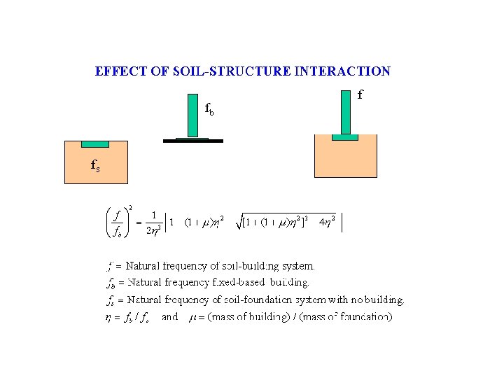
 EFFECT OF SSI ON NATURAL FREQUENCY OF STRUCTURE f/fb h=fb /fs
 INSTRUMENTATION FOR SOIL-STRUCTURE INTERACTION
 ROTATION OF BEAM-COLUMN JOINTS Case 1: • No joint rotations • Floors remain horizontal • Most rigid • Generally assumed case Case 2: • Equal joint rotations within each floor • Floor slabs do not deform • More flexible than Case 1 Case 3: • No restrictions on joint rotations • Floor slabs deform • Most flexible
 EFFECTS OF JOINT ROTATIONS 20 -STORY STEEL-FRAME BUILDING (from Dynamics of Structures, Hurty and Rubinstein, 1964) • Case 1: No joint rotations f=0. 61 Hz ( T=1. 63 sec. ) • Case 2: Equal joint rotations within each floor f=0. 31 Hz ( T=3. 25 sec. ) • Case 3: No restrictions on joint rotations f=0. 29 Hz ( T=3. 41 sec. )
 DISTRIBUTION OF FORCES BETWEEN FRAMES AND SHEAR WALLS Frame structures Flexural deformations Shear walls Shear deformations Real life: Frame + shear wall Deformations ? ? ?
 IN-PLANE FLEXIBILITY OF FLOOR SLABS Frame Shear wall Sensors Force Rigid diaphragm Force Flexible diaphragm
 KEY COMPONENTS Ø Each structural instrumentation project is a research project involving a field experiment. Ø Each instrumentation addresses to an unresolved problem in earthquake engineering. Ø Process involves peer-reviewed proposals open to both internal and external researchers. Ø USGS External Grants program can be used as a model.
 RESPONSIBILITIES • Once the proposal is approved, the researcher will be in charge of : Ø management of budget, Ø building selection and permits, Ø instrument selection, design, and installation, Ø data processing and analysis Ø releasing data according to standards set by USGS.
 RESPONSIBILITIES • The USGS’s role will be to: Ø provide funds, and if needed purchase the instruments, Ø help with the installation and provide maintenance, Ø set the standards for data collection and dissemination, Ø take over the instrumentation if required.
 ADVANTAGES Ø RFP and peer-review process will help to maximize the scientific benefits. Ø The USGS program will have its own identity, which is different than but complimentary to the CDMG program. Ø Each instrumented structure will have a scientific owner who will take care of the structure and data. Ø Some of the time-consuming tasks, such as selection of buildings, obtaining permits, and data collection and processing will no longer be the responsibility of the USGS. Ø The process will help to increase the number of outside engineers/researchers that are involved, which should create more support for the ANSS and the USGS.
 DISADVANTAGES Ø The cost of instrumentation might increase due to salary and overhead costs in proposals from outside researchers. Solution: USGS buys the instruments. Ø Having different people doing different types of instrumentation might create problems with the standardization for data archiving and dissemination. Solution: The USGS sets the standards and closely monitors the projects to make sure standards are followed.
 Issues for Consideration • Continuous monitoring is required in order to perform accurate damage assessment – ANSS must manage high-rate data streams • ambient vibrations during wind, construction, etc. • e. g. , 500 Hz Factor Bldg. - SEED format to IRIS • Permanent deformations are reliable indicators for damage - must utilize sensors other than accelerometers to observe such long-period, static deformation reliably
 Summary Ø Performance-based design requires accurate displacement observations, not only acceleration - the future of structural engineering relies on displacement data; existing acceleration and velocity data are inadequate, and only new instrumentation for permanent deformation will address this deficiency Ø The envisioned real-time damage indication system, “Damage. Map, ” is feasible now, yet requires true displacement observations not attainable with accelerometers alone - an investment in R & D is therefore needed as part of the ANSS program - such a system should be prototyped in an urban area with existing high-rate CGPS array and wireless (3 G) network for telemetry Ø RLGs, IFOGs, MEMs and GPS complement accelerometers (which alone are deficient in measuring displacement, tilt and rotation) - these sensors are dropping rapidly in cost - should be used in ANSS structural monitoring Ø Instrumentation deployments should be proposal-driven and peer-reviewed so as to provide best scientific and engineering return on the ANSS structural monitoring investment