0729741e9eea8f0c4028aaf27d662960.ppt
- Количество слайдов: 41


SST electrical cable qualification Simone Paoletti CERN, 11 July 2006

Routing of the Power in the SST PSUs will be placed on “balconies” in the experimental cavern (UXC), ~10 m (direct) distance from the beams crossing point. From there: Power cables will be used also to route signals from T and H probes inside the tracker • ~35 m of cables will be needed to reach the “patch panel 1” (PP 1) A Cu cable is to be used in this region, in order to have better performances • ~6 m of cables will be needed to reach the tracker internal structures from PP 1. An Al cable is to be used in this region, in order to keep low the material budget. “Balconies” ~ 35 m PSU Crates Cu Cable - COST and PERFORMANCE - Detector volume Tracker “Patch Panel 1” ~6 m Tracker structures Al Cable - MATERIAL BUDGET -
 cables")
short ( 6 m) cables
 cables")
long ( 30 m) cables

Quality Control • All cables are checked upon reception before being used for the experiment – LIC, PLCC, TIB/TID short cables automatic test setup checking connections, isolation and capacitance – TEC/TOB short cables Lyon box checking connections and isolation. • Each cable is checked at production by the connectorising firm: – QC checks for PLCC and LIC after connectorisation were agreed with us. • For the LIC cables additional QC tests are performed by the cable producing firm, before connectorisation, as specified in the tender. – Standard qualification tests on all produced spools – Sampling destructive tests

The LIC cable

The LIC cable Two versions: • v 1 for TIB/TID • v 3 for TEC/TOB • the connectorisation of he two versions is compatible (TEC/TOB may use LIC_v 1 and vice-versa) “LIC V 1” All relevant documentation (design, tests, safety) is on EDMS: https: //edms. cern. ch/ First steps of PRR passed: • the LIC cable was approved for safety • we are allowed to buy the cables • still missing cable lengths definition inside CMS cabling database “LIC V 3”
")
LIC QC before connectorisation • The LIC is produced by Elettronica Conduttori (Volpiano, TO) • Each production lot is certified by the firm according to contract and to CERN-required specifications: – IEC 60317 -0 -1, IEC 60317/51, CEI 20 -11, CEI 20 -35, IEC 60332 -1, 73/23/CEE, 93/68/CEE, 2002/95/CEE, TECH SPEC. LIC V 1, LIC V 3 • The manufacturer performs the following isolation tests, on each spool, before cutting to individual lengths: – – – 3000 Vcc (between twisted pairs) 2000 Vcc (twisted versus shield braid) 3000 Vcc (twisted versus enamelled) 250 Vcc (enamelled vs shield braid) • The certified working voltages are: – 30 V for the enamelled wires (LV lines) – 600 V for the twisted pairs (HV, LV senses and T, H probes)

Production lot certificate
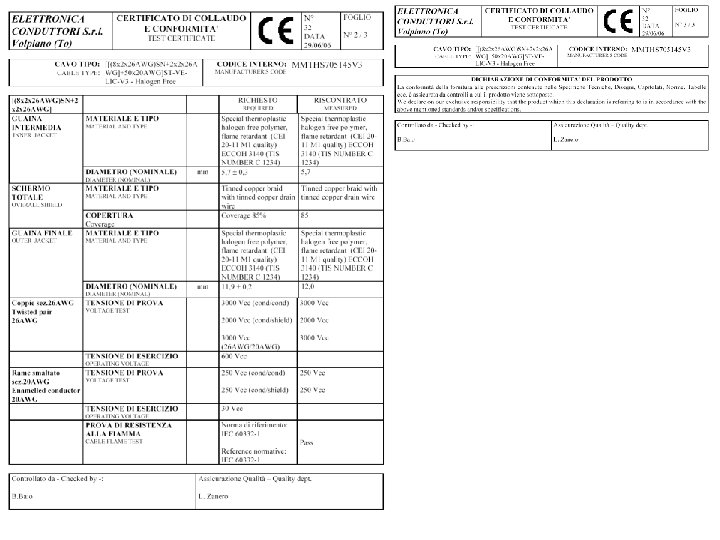

Electrical test results

LIC QC: destructive tests • Additional destructive tests are performed on each production lot, on a sample basis, in order to spot possible mechanical problems – These tests are not addressing any weakness specific of the LIC cable, but were required as a safety measure, since the LIC cable design is new (use of enamel wire). • Traction – 820 N / 60 s • “U” bends – 200 cycles (Rbend = 75 mm) + 5 cycles (Rbend = 20 mm) • Crushing – 150 kg on 80 mm length • The electrical properties of the cable samples are measured after the destructive tests and have to be good within large safety margins

Traction test

Crush test

Bending test

Bending radius • The LIC is certified for Rbend = 8 cm – Rule of thumb (“average” manufacturer): Rbend ~ 10 x ø • The QC procedure was agreed with the manufacturer in order to allow us to lower Rbend in a few difficult installation points – Once bent below 8 cm, any further movement of the cable is strongly discouraged – We have to keep Rbend as large as we can during the installation • It is a single-pose cable – the characteristics and costs of movement cables are different (cost higher by ~ factor 3) – we can re-use this cable a limited number of times, provided it is adequately handled and never bent below 8 cm – some bad handlings which can damage the cable (from my personal experience): • drop from height while fastened at the bottom • wrong re-winding into drum

Outer jacket • The jacket material is ECCOH 3140 LS 0 H polyolefin compound – satisfies CERN IS 23 safety rules (fire and radiation resistance) – similar compound (Megolon S 304) used in previous LIC preproduction – polyolefin compounds used by several sub-detectors • The jacket is 1 mm thick – adequate to the cable dimensions – constraints: • occupancy on cable trays • bending radius • power consumption

Connectorisation • Connectorisation technique for enamel wires developed: – bath in tin/lead at 390°C • initial technical problems due to the constrained dimensions in PP 1 solved • molding technique developed using polyurethane (Rampf’s RAKO-PUR) PSU end PP 1 end insertion key

Connectorisation schemes

Tests performed after connectorisation • Continuity and isolation tests performed at the firm using a programmable tester machine: – SCHAFFNER ELECTROTEST SYSTEM W 427 • More refined tests (using the same instrument) performed at CERN upon cable reception: – “four point” R measurement allows to monitor the quality of connections – capacitance measurements ensure the correct twisted pair assignments

Test performed by firm

Test performed at CERN: SCHAFFNER ELECTROTEST SYSTEM W 427 ---------------------Programma di test: LIC versione 3 (35 metri) Nome del file : LIC_V 3 -35 mt Data/ora : 06/06/2006 15. 00. 55 Seriale : 213 header Test APERTI Parameter: R=8. 500 Ohm I=200. 0 m. A Tmin=2. 000 ms Tmax=2. 000 ms Test CORTI Parameter: R=100. 0 k. Ohm U=20. 00 V Tmin=5. 000 ms Tmax=5. 000 ms Test HV-DC Parameter: R=1. 500 GOhm U=1000 V Tempo salita=1000 V/Ms Tmin=500. 0 ms Tmax=200. 0 ms tests against shorts (20 V) Test CORTI -----R=100. 0 k. Ohm U=20. 00 V Tmin=5. 000 ms Tmax=5. 000 ms NCL S >100. 00 MOhm NCL R 32. 00 MOhm NCL B 6. 106 MOhm NCL P 61. 54 MOhm NCL X >100. 00 MOhm NCL Y >100. 00 MOhm NCL V >100. 00 MOhm NCL W 100. 00 MOhm NCL T >100. 00 MOhm NCL U >100. 00 MOhm NCL N >100. 00 MOhm NCL O >100. 00 MOhm NCL L >100. 00 MOhm NCL M >100. 00 MOhm NCL J >100. 00 MOhm NCL K >100. 00 MOhm NCL H >100. 00 MOhm NCL I 100. 00 MOhm NCL F >100. 00 MOhm NCL G >100. 00 MOhm NCL D >100. 00 MOhm NCL E >100. 00 MOhm NCL A >100. 00 MOhm NCL C 100. 00 MOhm NCL FM 36 -CASE >100. 00 MOhm NCL FM 36 -31 11. 59 MOhm NCL FM 36 -30 100. 00 MOhm NCL FM 36 -27 >100. 00 MOhm NCL FM 36 -12 >100. 00 MOhm NCL FM 36 -9 100. 00 MOhm NCL FM 36 -10 >100. 00 MOhm NCL FM 36 -8 >100. 00 MOhm NCL FM 36 -4 100. 00 MOhm

Test APERTI Parameter: R=8. 500 Ohm I=200. 0 m. A Tmin=2. 000 ms Tmax=2. 000 ms Conn. Conn. J K U C O H G A I N Y X V W L M F T E D FM 36 -2 FM 36 -1 FM 36 -3 FM 36 -6 FM 36 -5 FM 36 -7 FM 36 -11 FM 36 -14 FM 36 -13 FM 36 -15 FM 36 -20 FM 36 -19 FM 36 -22 FM 36 -21 FM 36 -24 FM 36 -23 FM 36 -26 FM 36 -25 FM 36 -28 FM 36 -29 4. 770 Ohm [7] T 24. 775 Ohm [8] T 2+ 4. 770 Ohm [9] T 3+ 4. 750 Ohm [10] Vbias 4 4. 745 Ohm [11] Vbias 1 4. 845 Ohm [12] Vbias 7 4. 712 Ohm [13] Vbrtn 1 4. 772 Ohm [14] Vbias 5 4. 850 Ohm [15] Vbias 2 4. 825 Ohm [16] Vbias 8 4. 715 Ohm [17] Sense 2504. 760 Ohm [18] Sense 250+ 4. 735 Ohm [19] Sense 1254. 717 Ohm [20] Sense 125+ 4. 932 Ohm [21] T 14. 695 Ohm [22] T 1+ 4. 727 Ohm [23] Vbrtn 2 4. 762 Ohm [24] T 34. 797 Ohm [25] Vbias 3 5. 313 Ohm [26] Vbias 6 continuity tests (tw pairs) drains Test APERTI Parameter: R=600. 0 m. Ohm I=200. 0 m. A Tmin=2. 000 ms Tmax=2. 000 ms Conn. FM 36 -CASE FM 36 -case 385. 5 m. Ohm [29] Case Conn. FM 36 -16 FM 36 -17 389. 1 m. Ohm [30] Drain 2 Conn. FM 36 -16 FM 36 -18 422. 9 m. Ohm [30] Drain 2 Conn. FM 36 -16 FM 36 -31 557. 0 m. Ohm [30] Drain 2 Conn. FM 36 -16 FM 36 -32 582. 4 m. Ohm [30] Drain 2 Test APERTI Parameter: R=60. 00 m. Ohm I=200. 0 m. A Tmin=2. 000 ms Tmax=2. 000 ms Conn. B FM 36 -A 1 47. 91 m. Ohm [35] GND Test APERTI Parameter: R=80. 00 m. Ohm I=200. 0 m. A Tmin=2. 000 ms Tmax=2. 000 ms Conn. S FM 36 -A 2 64. 94 m. Ohm [37] V 250 Test APERTI Parameter: R=170. 0 m. Ohm I=200. 0 m. A Tmin=2. 000 ms Tmax=2. 000 ms Conn. R FM 36 -A 3 161. 9 m. Ohm [39] V 125 Test APERTI Parameter: R=300. 0 m. Ohm I=200. 0 m. A Tmin=2. 000 ms Tmax=2. 000 ms Conn. P FM 36 -A 4 231. 9 m. Ohm [41] Drain 1 LVs
 one vs all others DC-NCA DC-NCA DC-NCA DC-NCA DC-NCA J")
isolation tests (1000 V) one vs all others DC-NCA DC-NCA DC-NCA DC-NCA DC-NCA J K U C O H G A I N Y X V W L M F T E D 17. 91 GOhm [47] T 214. 58 GOhm [48] T 2+ 99. 34 GOhm [49] T 3+ 17. 21 GOhm [50] Vbias 4 14. 28 GOhm [51] Vbias 1 129. 6 GOhm [52] Vbias 7 159. 9 GOhm [53] Vbrtn 1 24. 26 GOhm [54] Vbias 5 20. 46 GOhm [55] Vbias 2 7. 883 GOhm [56] Vbias 8 16. 13 GOhm [57] Sense 25012. 66 GOhm [58] Sense 250+ 15. 16 GOhm [59] Sense 12512. 02 GOhm [60] Sense 125+ 11. 72 GOhm [61] T 19. 986 GOhm [62] T 1+ 22. 39 GOhm [63] Vbrtn 2 18. 43 GOhm [64] T 3155. 6 GOhm [65] Vbias 3 130. 0 GOhm [66] Vbias 6 Test HV-DC Parameter: R=10. 00 MOhm U=200. 0 V Tempo salita=500 V/s Tmin=1. 000 s Tmax=200. 0 ms DC-NCA B 419. 7 MOhm [69] GND DC-NCA S 511. 4 MOhm [70] V 250 DC-NCA R 1. 430 GOhm [71] V 125 Test HV-DC Parameter: R=1. 500 GOhm U=1000 V Tempo salita=1000 V/Ms Tmin=500. 0 ms Tmax=200. 0 ms DC-NCA FM 36 -4 20. 38 GOhm [74] Empty DC-NCA FM 36 -8 22. 76 GOhm [75] Empty DC-NCA FM 36 -9 21. 65 GOhm [76] Empty DC-NCA FM 36 -10 22. 09 GOhm [77] Empty DC-NCA FM 36 -12 22. 74 GOhm [78] Empty DC-NCA FM 36 -27 22. 18 GOhm [79] Empty DC-NCA FM 36 -30 22. 18 GOhm [80] Empty twisted pair capacitance C-Twist T+01/T-01 FM 36 -23 FM 36 -24 C-Twist T+02/T-02 FM 36 -1 FM 36 -2 C-Twist T+03/T-03 FM 36 -25 C-Twist Vbias 1/Vbias 4 FM 36 -5 FM 36 -6 C-Twist Vbias 2/Vbias 3 FM 36 -13 FM 36 -28 C-Twist Vbias 5/Vbias 6 FM 36 -14 FM 36 -29 C-Twist Vbias 7/Vbias 8 FM 36 -7 FM 36 -15 C-Twist Vbrtn 1/Vbrtn 2 FM 36 -11 FM 36 -26 C-Twist S 250+/S 250 - FM 36 -19 FM 36 -20 C-Twist S 125+/S 125 - FM 36 -21 FM 36 -22 C-Twist Drain 1/GND FM 36 -A 4 FM 36 -A 1 C-Twist Drain 2/GND FM 36 -31 FM 36 -A 1 Risultato del Test ------------------Test APERTI : B U O N O Test CORTI : BUONO Test COMPONENTI : B U O N O Test HV-DC : BUONO Test HV-AC : non attivo Test Shield : non attivo Messaggi errore : B U O N O 3. 029 n. F [84] 2. 890 n. F [85] 3. 327 n. F [86] 3. 256 n. F [87] 3. 417 n. F [88] 3. 313 n. F [89] 3. 393 n. F [90] 3. 190 n. F [91] 3. 593 n. F [93] 3. 464 n. F [94] 60. 03 n. F [96] 28. 08 n. F [97]

First LIC_V 1 sample

first 35 m LIC prod. deliveries Summer !

Experience with LIC cables • LIC cable prototypes have been used to power our detectors with our PS system since more than three years • Around 270 LIC cables are in use: – 2003/2004 prototypes – 2005 pre-production – 2006 first deliveries • Their performance is good – several of them installed a lot of times and survived bad handlings: • test beams • Louvain irradiation tests • PSU test setup • Few problems reported so far: – regarding damage of outer jacket (de-coloring, perforation or peeling) • Proper handling procedure, according to the cable specs, has to be adopted and trained manpower has to handle the cables: – never bend below nominal bending radius – never pull over sharp edges – use some specific (slippery) product to de-install the cable • If not, we don’t have cables for TIF ! (or for CMS !)
")
Experience with connectors • One weakness of the FM 36 W 4 (pp 1) connectorisation spotted after first prototypes – occasional contact of LVs, now solved • Pins may occasionally get pushed inside the bajonet connector – it’s not a damage: they can be simply repositioned with tweezers • Occasional difficulty in plugging the cable into the PSU back-boards – limited experience with this kind of problems: too few and incomplete problem reports – from personal experience: it’s better to follow the natural torsion of the cable. Do not try to exercise too much force in de-torsion • the thicker 40 A pins may get distorted • not a damage: the pins get back into position when the torsion force is released • General rule of thumb: – do not exaggerate with the force applied in connecting the cables – never try to force the connector’s guide insertion key

Power long control cables

The PLCCs • 20 PLCC_TIB/TID + 20 PLCC_TOB prototypes produced in 2005 – currently used in integration setups and MTCC • production with final connectors just started – PLCC_TIB/TID the first one to be produced • Electrical tests (same kind as for LIC) performed both by connectorising firm and at CERN, upon reception PLCC TEC TOB TIB/TID
 PLCC_TIB/TID (92 + Rconn. expected)")
20+20 PLCC test production PLCC_TIB/TID (151 + Rconn. expected) PLCC_TIB/TID (92 + Rconn. expected)

Short cables

TIB/TID cables CAB 60 Cu– 6 m-ctrl 2 twp senses LV senses Section: 2. 5 mm 2 (Habia) (Novacavi) 4 HVbias + 2 RTN 12 wires for T, H probes • Electrically tested (opens and shorts) at the connectorising firm (ADAPT) • Tested upon reception at CERN with the usual cable testing machine.

typical CAB 60 test SCHAFFNER ELECTROTEST SYSTEM W 427 ---------------------Programma di test: CAB 60 Nome del file : CAB_60 Data/ora : 10/05/2006 14. 26. 14 Seriale : 249 -560 continuity tests Test APERTI Parameter: (cut at R = 1. 5 W) R=1. 500 Ohm I=200. 0 m. A Tmin=2. 000 ms Tmax=2. 000 ms Test CORTI Parameter: R=100. 0 k. Ohm U=20. 00 V Tmin=5. 000 ms Tmax=5. 000 ms isolation tests (1000 V) Test HV-DC Parameter: R=1. 500 GOhm U=1000 V Tempo salita=1000 V/Ms Tmin=500. 0 ms Tmax=20. 00 ms Test CORTI -----R=100. 0 k. Ohm U=20. 00 V Tmin=5. 000 ms Tmax=5. 000 ms NCL FM 36 -CASE >100. 00 MOhm NCL FM 36 -01 >100. 00 MOhm NCL FM 36 -02 >100. 00 MOhm … NCL FM 36 -A 2 >100. 00 MOhm NCL FM 36 -A 3 >100. 00 MOhm Conn. FM 36 -19 FM 36 -20 FM 36 -21 FM 36 -22 FM 36 -05 FM 36 -28 FM 36 -07 FM 36 -29 FM 36 -11 FM 36 -26 FM 13 -05 FM 13 -04 FM 13 -10 FM 13 -09 FM 13 -01 FM 13 -02 FM 13 -07 FM 13 -06 FM 13 -08 FM 13 -03 1. 095 Ohm 1. 205 Ohm 1. 007 Ohm 1. 028 Ohm 1. 083 Ohm 1. 092 Ohm 1. 066 Ohm 1. 092 Ohm 1. 044 Ohm 1. 074 Ohm [7] Sense 250+ [8] Sense 250[9] Sense 125+ [10] Sense 125[11] Vbias 1 [12] Vbias 2 [13] Vbias 3 [14] Vbias 4 [15] Vb. RTN 1 [16] Vb. RTN 2

Test APERTI Parameter: R=800. 0 m. Ohm I=200. 0 m. A Tmin=2. 000 ms Tmax=2. 000 ms Conn. FM 36 -CASE FM 36 -case 368. 9 m. Ohm [19] CASE-FM 36 Conn. FM 36 -16 FM 36 -17 385. 9 m. Ohm [20] Drain 2 Conn. FM 36 -16 FM 36 -18 386. 9 m. Ohm [20] Drain 2 Conn. FM 36 -16 FM 36 -31 636. 5 m. Ohm [20] Drain 2 Conn. FM 36 -16 FM 36 -32 642. 0 m. Ohm [20] Drain 2 Conn. FM 36 -16 FM 13 -CASE 570. 1 m. Ohm [20] Drain 2 Conn. FM 36 -16 FM 13 -case 566. 8 m. Ohm [20] Drain 2 Test APERTI Parameter: R=100. 0 m. Ohm I=200. 0 m. A Tmin=2. 000 ms Tmax=2. 000 ms Conn. FM 36 -A 4 FM 13 -CASE 74. 84 m. Ohm [24] Drain 1 Conn. FM 36 -A 3 FM 13 -A 3 84. 08 m. Ohm [25] V 125 Test APERTI Parameter: R=60. 00 m. Ohm I=200. 0 m. A Tmin=2. 000 ms Tmax=2. 000 ms Conn. FM 36 -A 2 FM 13 -A 2 51. 13 m. Ohm [27] V 250 Test APERTI Parameter: R=40. 00 m. Ohm I=200. 0 m. A Tmin=2. 000 ms Tmax=2. 000 ms Conn. FM 36 -A 1 FM 13 -A 1 32. 78 m. Ohm [29] GND DC-NCA FM 36 -19 103. 2 GOhm [33] Sense 250+ 80 m. W expected 53 m. W expected 33 m. W expected

DC-NCA DC-NCA DC-NCA DC-NCA DC-NCA DC-NCA DC-NCA FM 36 -20 FM 36 -21 FM 36 -22 FM 36 -05 FM 36 -28 FM 36 -07 FM 36 -29 FM 36 -11 FM 36 -26 FM 36 -01 FM 36 -02 FM 36 -03 FM 36 -04 FM 36 -06 FM 36 -08 FM 36 -09 FM 36 -10 FM 36 -12 FM 36 -13 FM 36 -14 FM 36 -15 FM 36 -23 FM 36 -24 FM 36 -25 FM 36 -27 FM 36 -30 23. 26 GOhm [34] Sense 25025. 16 GOhm [35] Sense 125+ 93. 02 GOhm [36] Sense 12585. 11 GOhm [37] Vbias 1 >4000 GOhm [38] Vbias 2 21. 51 GOhm [39] Vbias 3 26. 89 GOhm [40] Vbias 4 85. 11 GOhm [41] Vb. RTN 1 85. 11 GOhm [42] Vb. RTN 2 13. 26 GOhm [43] Empty 186. 0 GOhm [44] Empty 85. 11 GOhm [45] Empty 85. 11 GOhm [46] Empty 164. 9 GOhm [47] Empty 10. 06 GOhm [48] Empty 9. 662 GOhm [49] Empty 82. 05 GOhm [50] Empty 85. 11 GOhm [51] Empty 85. 11 GOhm [52] Empty 421. 1 GOhm [53] Empty 11. 78 GOhm [54] Empty 8. 806 GOhm [55] Empty 14. 71 GOhm [56] Empty 145. 5 GOhm [57] Empty 85. 11 GOhm [58] Empty 85. 11 GOhm [59] Empty C-Twist S 250+/S 250 - FM 36 -19 FM 36 -20 C-Twist S 125+/S 125 - FM 36 -21 FM 36 -22 C-Twist Drain/GND FM 13 -CASE FM 13 -A 1 Risultato del Test ------------------Test APERTI : B U O N O Test CORTI : BUONO Test COMPONENTI : B U O N O Test HV-DC : BUONO Test HV-AC : non attivo Test Shield : non attivo Messaggi errore : B U O N O ------------ 380. 7 p. F [61] 376. 7 p. F [62] 1. 767 n. F [63] isolation tests

TEC/TOB cables • CAB 60, CAB 48, CAB 36 and ctrl-pwr-s 1 • The cable material is qualified at Habia: visual inspection, mechanical and geometrical checks, resistance measurements • The cables are tested at ADAPT: 1. mechanical and geometrical checks 2. pin-to-pin continuity test and short check; 3. hv test at 1 KV (absorbed current and insulation among HV wires); (Habia) • visual inspection and electrical tests (Lyon test box) at CERN 1. pin-to-pin continuity test and short check; 2. hv test at 600 V (absorbed current (information from G. Magazzu`) and insulation among HV wires);

Data base • Each cable used in CMS has to appear in the cabling database: • start point • end point • ID • Each cable is labeled by firm after connectorisation – type, date, length, serial number • We intend to store general cable information (production date, length, some of test results) in our construction database – part of the structure already defined • Cannot glue multiple labels on the same cable: – the IDs assigned by the cabling database have to match those of the construction database, and possibly resemble the serial number assigned by the firm. • Two-D labels will be used for short cables • We have to think carefully to which labels, and where, should be stuck on long (LIC and PLCC) cables.

Further installation issues • Do we check cables once they are installed in P 5 ? – topic still under discussion – short cables: no way, I guess – long cables: • electrical tests with cable tester from the balcony (short pairs of cables at PP 1) • test complete LV and HV chain after the cable is plugged into the PSU, using a test box in PP 1 – we may benefit from the monitoring provided by the PP 1 interconnect board – is the installation scenario allowing to use powered racks ? • Can we repair cables after installation ? – PP 1: forget it – balcony: it might be possible (depends on kind of damage) • Cable spares: – – we can foresee producing some spares we are heavily limited by space on cable trays have still to define the final cable distribution “hope” to place one or two spares per PP 1 • at least PLCC spare
0729741e9eea8f0c4028aaf27d662960.ppt