aa671b74da7bb3ed23a9fdf9463258cd.ppt
- Количество слайдов: 46


 Joonhong Park Yonsei CEE Department 2015.")
Solid Waste Management and Sustainability Technology (NOTE 6) Joonhong Park Yonsei CEE Department 2015. 11. 01

Landfill Technology: Contents Planning, Siting and Permitting of Landfills Landfill Processes Landfill Design

Background How residues that have no value can best be managed and disposed of. Is Land the best location for waste disposal? (ocean, space, etc). Combustion and then Landfill (EU) vs. Landfill as a bioreactor (US) One the most difficult facility to plan, site and permit.
, 30 year (an appropriate long-term plan), longer")
Planning Design Period: 10 year (short-term plan), 30 year (an appropriate long-term plan), longer than 50 year (difficult to predict). Sufficient landfill capacity for a design period - MSW (compaction effect has to be considered). - coverage (20 -50% of the volume of the landfill) - An in-place density of “ 700 kg/m 3” - facilities for its treatment processes (leachate, gas, special waste treatments). Factors affecting the volume requirement after landfill construction (new regulations, competing facilities, different cover options, nonresidential waste changes)

Volume Reduction An important design and operational variable. Step 1. Set the compaction density (compacted bulk density) in landfill (1200 lb/yd 3 or 700 kg/m 3), ρc Volume basis Mass basis Step 2. calculate the overall density, ρo Step 3. Calculate the fraction remaining of initial volume as a result of compaction (volume reduction), F F = ρ o/ ρ c

Calculation of landfill capacity Year 1 2. . 20 Total population Per capita generation rate (mass rate) Diversion fraction 5. 6 5. 8 0. 25 0. 35 6. 4 Waste to landfill, (mass) Waste to landfill, (volume) 0. 35 One year volume Accum. One year’s volume = [(Population) x (per capita generation rate) x (1 -Diversion) x 356 d/yr] / (compacted bulk density) Landfill Capacity (T) = cover soil volume (0. 25 * T) + accumulative volume
 -")
Siting The execution is far from easy. - NOPE (Not on Planet Earth) - NIMTO (Not In My Term of Office) Step 1: Determination of geographic boundary. Step 2: Identification of “unsuitable” locations. - Fatal flaw analysis (wetlands, flood plain, seismic zone, endangered species habitat, close to airport, GW recharge area, unsuitable soil conditions). Step 3: Ranking potential locations (population, land use, groundwater quality, visual and noise impact, soil condition, proximity to the centroid of solid waste generation. )
 - Examination of requirements")
Permitting Subtitle D of RCRA (Resource Conservation and Recovery Act) - Examination of requirements (siting, design requirements, operating conditions, groundwater monitoring, landfill closure, post closure, and financial assurance). - Combination of performance standards and design standards. Other - Permitting for land use conformance, air emissions, groundwater and surface waster discharge, operations, extraction for cover material and closure - Cost for Taking Land Compensation for Relocation

Landfill Processes - Biological degradation - Leachate Production - Gas Production
 67%")
Biological Degradation 45 -60% organic matter among refuse (proteins, lipids, carbohydrates, and lignins) 67% of the organic matter is biodegradable. - Readily biodegradable fraction (food and garden wastes) - Moderately biodegradable fraction (paper, textiles, and wood) 33% of the organic matter is recalcitrant (nondegradable or very difficult to degrade).

Predominant decomposition pathways Proteins Carbohydrates Lipids Amino acids Simple sugars Glycerol /LCVAs Hydrogen/CO 2 Methane Fermentation. SCVAs Acetate Methane + Methanogenesis CO 2 Acetate Acid formation

Landfill Ecosystem Soil microbes are responsible for major rate limiting steps of biodegradation of organic wastes. High degree of diversity due to heterogeneous nature of waste and landfill operating characteristics. The greater microbial diversity, the more stable the system against environmental perturbation. Electron donor (ED) and Electron acceptor (EA) - Rich in EDs (organic matters) - Predominant EAs: CO 2 and sulfate.

Seven key microbial groups in MSW stabilization steps Microbial group Substrate Amylolytic bacteria Proteolytic bacteria Celluloytic bacteria Hemicellulolytic bacteria Hydrogen-oxidizing methanogenic bacteria Acetoclastic methanogenic bacteria Sulfate-reducing bacteria Starches Proteins Cellulose Hemicellulose Hydrogen Acetic acid Sulfate

Phases in MSW Stabilization Phase I – Initial Adjustment - initial placement of MSW and accumulation of moisture - acclimation to activate microbial communities Phase II - Transition Phase - Aerobic environment => anaerobic environment - EA use is shifted from O 2 to sulfate/nitrate - hydrolysis Phase III - Acid Formation Phase - Conversion into VO acids by acid-formers (decrease in p. H, metal mobilization) - Rapid consumption of sulfate and nitrate

Phases in MSW Stabilization Phase IV- Methane Fermentation Phase - VO acids are consumed by methane-forming bacteria and converted into methane and CO 2. - Sulfate => Sulfides; nitrate => NH 4 - p. H increase but self controlled by bicarbontate buffer system (helpful in methanogenesis) - Heavy metal transport by complexation and precipitation.

Phases in MSW Stabilization Phase V- Maturation Phase - Limitation of EAs and EAs results in dormancy. - Gas production drops; leachate pollutant concentration decreases; reappearance of oxygen - Slow degradation of resistant organic fractions continues with the production of humic-like substrates
 Total VOCs")
Phases in MSW Stabilization Transition Acid Formation Methane Fermentation Maturation COD (mg/l) Total VOCs (mg/l) Ammonia-N (mg/l) p. H 480 -18, 000 1, 500 -71, 000 580 -9, 760 31 -900 100 -3, 000 -18, 800 250 -4, 000 0 120 -125 2 -1, 030 6 -430 6. 7 4. 7 -7. 7 6. 3 -8. 8 7. 1 -8. 8 Conductivity (μS/cm) 2, 450 -3, 310 1, 600 -17, 100 2900 -7, 700 1, 4004, 500

Leachate Production ØDefinition of Leachate: polluted water generated from MSU landfill. ØQuantity ØQuality
 Infiltration Interception and Evaporation by vegetation Evapotranspiration (E)")
Leachate Production - Quantity Precipitation (P) Infiltration Interception and Evaporation by vegetation Evapotranspiration (E) Surface runoff (R) Percolation (C) Groundwater E (evapotranspiration, mm/yr) Moisture in MSW (S) Leachate production P (precipitation, mm/yr) R*P here R: runoff coeff. (dimensionless) (1 -R)*P S, storage within the soil or waste (mm/yr) Leachage Out (Percolation, C)
 – S - E ØHELP (Hydrologic")
Leachate Production - Quantity ØC = P(1 -R) – S - E ØHELP (Hydrologic Evaluation of Landfill Performance, the US Army Corps of Engineers): good at long-term prediction of leachate production and at comparision of various design alternatives. ØStudy Example 4 -3. Ø Hydraulic Retention Time (HRT) of leachate depends on operation history…(not easy)

Leachate Production - Quality ØHigh concentrations of organic pollutants (BOD= up to ~100, 000 ppm [cf. 200 ppm BOD in raw sewer) ØLead and Cadimum (from batteries, plastics, packaging, electronic applicances, light bulbs etc. ) ØSite-to-site specific leachate quality makes landfill design and operation very difficult (need to more detailed investigation of quality in leachate). ØNeed to pretreatment of young leachage to make it amenable to biodegradation.

Gas Production - Quantity ØGas Production = function (gas yield per MSW weight, lag time, shape of the lifetime gas production curve, and the duration of gas production). ØIn theory one of MSW produces 442 m 3 landfill gas containing 55% methane and a heat value of 19, 730 k. J/m 3). => In practice, only 10% efficiency…. . and many other variables.
 n QT")
Gas Production - Quantity ØLand. GEM (EPA model; www. epa. gov/ttn/catc. ) n QT = Σ 2 k Lo Mi e-k * ti i=1 QT: total gas emission rate from a landfill, volume/time n = total time periods of waste placement k = landfill gas emission constant, time-1 Lo = methane generation potential, volume/mass of waste ti = age of the i th section of waste, time Mi = mass of wet waste, placed at time i.
 Methane Carbon dioxide Nitrogen (N")
Gas Production - Quality Component % by volume (dry) Methane Carbon dioxide Nitrogen (N 2) Oxygen Ammonia Hydrogen 45 -60 40 -60 2 -5 0. 1 -1. 0 0 -0. 2 ØMethane is a potent green-house gas ØMany of VOCs are odorous and/or toxic.

Landfill Design - Liners - Leachate collection, treatment, and disposal - Landfill gas collection and use
 Leachate")
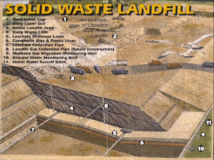
Design Components Final Cover Gas control Methane monitoring Waste Liner (synthetic or Natural) Leachate Collection System Groundwater Monitoring well
 HDPE Liner GCL (geosynthetic clay")
Liner Systems for MSW Landfills LCS (Leachate Collection Sys) HDPE Liner GCL (geosynthetic clay liner) Geomembrane single-liner system Low permeability soil single-liner system LCS (Leachate Collection Sys) LCS GCL Low permeability soil single-liner system GCL LDS (Leachate Detection System) Double liner system With bottom composite liner

Components of LCS Ø protective and drainage layers ØPerforated collection lateral and header pipes ØPump station sump ØLeachate pump ØPump controls ØPump station appurtenances ØForce main or gravity sewer lines

Leachate-Collection System Design
 600 -1000 Max. leachate")
Leachate-Collection System Design Guideline Parameter Range Leachate loading rate (gpd/ac) 600 -1000 Max. leachate head (in) 9 -12 (30 cm) Pipe spacing, P (ft) 60 -400 Collection pipe dia. (in) 6 -8 Collection pipe material PVC or HDPE Pipe slope (%) 0. 5 -2 Drainage slope (%) = tan α 0. 2 -2 PLEASE STUDY EXAMPLE 4 -5. Median 750 11 180 8 HDPE 1 1
 Ø Biological -Activated sludge (BOD/COD): good for young")
Leachate Treatment Options (Table 4 -11) Ø Biological -Activated sludge (BOD/COD): good for young leachate -Aerated lagoons (BOD/COD): good for a small scale -Anaerobic (BOD/COD): good for high organic conc. Ø Physical/chemical - Coagulation/precipitation (heavy metals): good for Fe, Zn; little effective for Cd, Pb, and Ni. - Chemical oxidation (COD): efficient but requiring a great dosage. - Ion exchange (COD): 10 -70% COD removal, slight heavy metal removal. - Adsorption (BOD/COD): 30 -70% COD removal after biological or chemical treatment - Reverse osmosis (total dissolved solids): 90 -96% TDS removal. Of course expensive

Leachate Recirculation ØRecirculation of leachate back through the landfilled waste Ø Offers more rapid development of active anaerobic microbial populations and increases reaction rates and predictability of these organisms. Ø Moisture may result in reduced efficiency of Gas collection. Therefore, the location of leachate recirculaiton should be changed frequently (an integral part of landfill operations)
 -Greenhouse gases -Modern landfill")
Gas Recovery Gas (CO 2 50% and CH 4 50%) -Greenhouse gases -Modern landfill has facilities to use methane to generate electricity.

Gas Collection Ø Passive collection -vent collectors -release the gas to the atmosphere w/o treatment -typical spacing for a passive vent is one per 7500 m 3. Ø Active extraction - extract the gas under vacuum created by a central blower - typically vertical gas wells are used.
 - Interior")
Typical vertical gas well Casing: PVC or HDPE pipe (3 -8 in) - Interior Spacing: 200 -250 ft. - Perimeter Spacing: 100 -250 ft. - Min. slope 3% Wide Slots (High Permeability) Crushed Rock (High Permeability) Well Bore Seal Zone Well Depth (75% of depth or to water table) Impermeable Zone Well Bore Seal (Diameter 24, 30, or 36 in) Perforations (min. 25 ft) Cover Soil (Low Permeability)
 Ø Gas flow: v = Q/A -Q: landfill")
Pressure Drop Calculation (p. 145 -147) Ø Gas flow: v = Q/A -Q: landfill gas flow rate -A: cross-sectional interior area of the pipe Ø Pressure drop ∆P = ρ f L v 2/(2 g. D) - ρ: gas density = M. W. of the gas * Pressure /(R*T) - L: length of pipe - D: diameter of pipe - f: Darcy-Weisbach friction factor (function of roughness/D; attainable from a Moody diagram) - g: gravitational constant

Technical Issues in Gas Use Ø Gas Composition has significant impact on energy recovery, gas cleanup, collection and operation systems. Ø Effects of corrosives on equipment (organic acids, H 2 S, water vapor) ØEffect of particles on equipment (small soil particles, combustion of dimethyl siloxane [gas] into silica deposits) ØEffects of H 2 S and halide compounds on the efficiency of energy recovery from the gas.

Applications of Landfill Gas Use ØBoilers and other direct combustion applications (e. g. , vehicle fuel=> reduced NOx): economically feasible. ØConversion of landfill gas to synthetic fuels and chemicals (e. g. , hydrocarbon production, methanol synthesis): economically not feasible. ØElectrical power generation for internal combustion engines and gas turbines (the most common landfill gas-toenergy application; for large scale): the most profitable. Ø Electrical power generation for fuel cells (well established; higher energy efficiency; for small scale): also profitable. ØPurification to pipeline-quality gas (not that popular): ØTax incentives and favorable purchase price are key nontechnical issues.

Geotechnical Aspects of Landfill Design ØLandfill stability: Slope failures during the landfilling and after its closure. => potential for catastropes. ØCritical point of failure: soil/geosynthetic & geosynthetic/geosynthetic interfacial surfaces as well as waste slopes ØLandfill stability must be investigated under both static and seismic conditions. ØSeepage in a “bioreactor” landfill will result in slope failure. Ø side slopes ofcompleted and capped landfills be no greater than 1: 3 with 1: 4 being preferable. (risk versus design volume)

Stormwater Management ØControl of the size of the working place: higher than its surrounding area. Ø Placement of interim cover on the waste. ØRunon control: prevention of the introduction of stormwater to the active area of the landfill; a higher location, ditches, dikes, or culverts to divert flow. ØRunoff control: swales, ditches, berms, dikes, or Channel lining culverts. system Erosion control Outlet pipe

Landfill Cap ØPurpose: prevent the production of leachate after closure of a landfill. ØTypical side slope: - 1: 3 to 1: 4 - the interface friction bet. Adjacent layers must resist seepage forces - decrease the contact stresses between layers due to buildup of water and/or gas pressures.

Landfill Cap Plant Revegetated topsoil. Protective material Capillary force use Drainage material Clay barrier. Impermeable Gray (supporter) * Three mode of cap failures: Desiccation, Shear setting, and Rotation setting.

Landfill Operation ØLandfill Equipment ØFilling Sequences ØDaily Cover (disease control, odor and litter control, air emission, reducing the risk of fire, minimization of leachate production) Ø Monitoring (groundwater, gas)

Post-closure care and use of old landfills ØRequirements during post-closure period -Maintenance of the integrity and effectiveness of the final cover -Operation of the leachate collection system -Groundwater and gas-migration monitoring. ØFinal use alternatives -Golf courses - Natural areas -Recreation parks - Ski slopes -Parking lots - Building construction

Landfill Mining ØIf significant biodegradation occurs, it might be possible to dig up old landfills, separate the nonbiodegradable fraction, and use the dirt and organic soil as a cover material for present landfills. ØProblems…. . ØOnly shallow landfills that have few vertical lifts are candidates for landfill mining since they are most likely to have fully biodegraded. ØMay provide an economical alternative to the siting of new landfill.
aa671b74da7bb3ed23a9fdf9463258cd.ppt