

8f372692e14f069a5ea0446f198f7591.ppt
- Количество слайдов: 57
 Solar Cells need a top side conductor to collect the current generated They also need a conductive film on the backside
 Conductor Options
 Silver is the typical choice because it has the top conductivity However, Silver is an expensive conductor
 Silver is typically printed via a screen printer to keep manufacturing cost low
 Because of equipment and cost limitations, we will use vacuum deposition processes for our conductor
 Thin Film Deposition n Materials are deposited using a vacuum chamber n The vacuum chamber reduces the atmosphere to high vacuum levels (no atmosphere) n This reduces contaminating the films, provides a non-contaminating environment free of oxygen, water vapor, etc. and allows materials to melt at lower temperatures.
 Thin Film Deposition n Thin film deposition tools are very complex due to the need to create high vacuum levels. n Vacuum levels of 5 x 10 -7 torr and better are typical. Sea level atmospheric pressure is about 740 torr or 7. 4 x 10² n Because of their complexity, vacuum chambers are very expensive.
 Thin Film Deposition n To achieve high vacuum levels, several types of vacuum pumps are used. 1. 2. Mid level vacuum levels (2 x 10 -3 torr) are reached with rotary vane vacuum pumps. These pumps are also know as mechanical or roughing vacuum pumps High level vacuum levels are reached using n n n Diffusion vacuum pumps – requires liquid nitrogen to prevent oil contamination Turbomolecular pumps – like a small jet engine, clean and fast, good for processes that require the introduction of a process gas. Because of the high speed vanes, subject to catastrophic failure Cryogenic vacuum pumps – uses low temperature (10 o. K) – also clean and fast pumping but requires regeneration periodically which is time consuming
 Mid level vacuum pumps Roughing, fore line, mechanical Oil pump – oil can be standard hydrocarbon or inert synthetic (for extreme chemical pumping) Oil level must be monitored and replaced periodically Exhaust required and needs filter to trap oil droplets Uses no oil, usually an air or nitrogen bearing and seal Nitrogen and cooling water required Exhaust required
 Ultra High vacuum Pumps Cryogenic Pump Turbomolecular Pump
 Thin film deposition tools in the ECE Microelectronics Clean Room Cooke-thermal deposition CHA Mark 50 e-beam deposition CVC 601 -sputter deposition Varian 3125 e-beam deposition
 Conductor Deposition The Cooke thermal evaporator is not currently used. n The CVC sputter tool is used for aluminum depositions. A silver/antimony and copper targets are available. n The Varian 3125 and CHA Mark 50 e-beam deposition tools are used for all other conductors, Cu, Ag, Cr, Ni n – An e-beam evaporates material, it get the material so hot it becomes a gas and evaporates. It then travels in a straight line, because it is under vacuum, until it condenses when it strikes a colder surface
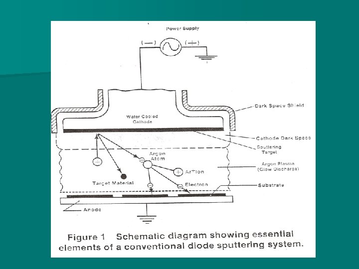
 With sputtering, an Argon plasma is formed, causing argon ions to strike a metal target and knock loose material. Because an electric field is created, material is deposited on the substrate Material target Substrate to be coated Argon plasma – ionized argon in an electric field
 E-beam Evaporation uses a high energy electron beam to vaporize (change from a solid to vapor) materials, especially metals
 Overall view of the Varian 3125 vacuum chamber. This tool deposits thin films using e-beam evaporation
 Portion of Varian 3125 control rack
 Varian 3125 quartz heater controller, shutter controller and planetary rotation controller Quartz heater controller E-beam shutter controller
 Electron beam power supply Typically 6 -8 KV are required to form the electron beam Electron beam can be steered by magnetic fields
 Cryopump temperature-must be below 15 o. K
 Varian 3125 ion gauge controller and deposition controller Ion Gauge controller Deposition controller
 Varian 3125 view of open chamber Wafer planetary – can rotate or stay stationary. Can be removed for loading
 Varian 3125 4 -pocket e-beam crucible
 evaporator the material is heated to a vapor (gas)") With an e-beam (electron beam) evaporator the material is heated to a vapor (gas) and then condenses on cooler surfaces Substrates (wafers) sit at the top of the chamber Molten material hot enough to vaporize (become a gas) Electron beam is formed and strikes the metal crucible
With an e-beam (electron beam) evaporator the material is heated to a vapor (gas) and then condenses on cooler surfaces Substrates (wafers) sit at the top of the chamber Molten material hot enough to vaporize (become a gas) Electron beam is formed and strikes the metal crucible
 Varian 3125 wafer planetary Wafer planetary for Varian 3125
 Varian 3125 Wafers are held down by spring clips
 Varian 3126 Quartz Heaters
 Varian 3125 door showing glass slide holder Glass slide must be replaced before each run
 Overall view of the CHA Mark 50 vacuum chamber. This tool deposits thin films using e-beam evaporation
 Inside of CHA Mark 50 chamber showing wafer platen – can be removed from the chamber and replaced with a larger wafer platen
 CHA Mark 50 wafer adapter ring Adapter ring for 4”/100 mm wafer Adapter rings are available for 2”, 3” and 4” wafers
 CHA Mark 50 4 -pocket e-beam crucible Four different materials are available to do sequential evaporations
 CHA Mark 50 crucible materials and chamber temperature monitor Materials currently inside the 4 pocket crucible are shown with their pocket number Pocket is chosen using this indexer
 CHA Mark 50 crystal oscillators for evaporation material thickness measurement Crystal oscillators
 New glass slides must be used for each evaporation
 CHA Mark 50 cryo-pump control Cryogenic pump temperature – should be around 20 o. K
 CHA Mark 50 vacuum gauge controller Vacuum chamber pressure. Gauge is showing a vacuum pressure of 7. 6 x 10 -6 torr. E-beam power supply is interlocked to prevent high voltage if pressure is too high
 CHA Mark 50 E-beam power supply and controller High voltage switch and current control Power supply main on/off switch Power supply is interlocked to prevent activation if vacuum pressure, cooling water, and zero current conditions are not met
 E-beam evaporation Crucible being heated by an electron beam
 Overall view of the CVC vacuum chamber. This tool deposits thin films using “sputtering”
 CVC 601 Sputter down configuration shown - the CVC has the target on the base and the wafers facing down Sputter up configuration On the Cameron CVC 601 1 - 8” DC aluminum target 2 - 3” RF targetsmultiple materials are available inch
 CVC sputter tool with chamber lid open Wafers are loaded into position
 Looking into the CVC sputter tool chamber, showing the 8” aluminum target Viewport – plasma can be seen here when sputtering 8 inch aluminum target
 CVC sputter tool control racks Argon flow MFC controller Press esc key to turn on Chamber vacuum gauge Must be restarted after automatic pump down
 Control rack – right side Chamber pressure needs to be in the 10 -6 torr range Cryo pump temperature must be below 20 o. K Do not sputter if cooling water alarm is sounding
 Control rack – left side RF matching network and power supply for 3 inch targets Shutters and RF target material tags Argon MFC controller Channel 1 Argon 30 sccm Channel 4 Argon 300 sccm
 CVC sputter tool DC power supply for aluminum target DC Voltage about 4 KV DC current 0. 5 to 2. 0 A
 CVC sputter tool view port
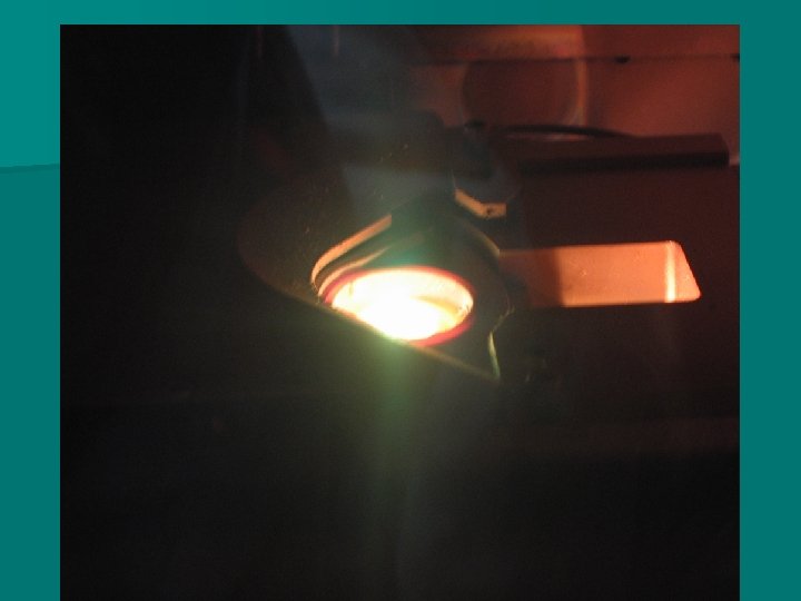
 View of argon sputter plasma in CVC sputter tool
 stage") View of argon plasma in AJA sputter tool Sputter target Shutter Substrate (wafer) stage Wafer stage can rotate and heat
View of argon plasma in AJA sputter tool Sputter target Shutter Substrate (wafer) stage Wafer stage can rotate and heat
 Once the wafer has been coated, the actual thickness of the metal can be measured The tool used to measure thickness is a surface profiler, in our lab it is the Alpha Step 200 In a surface profiler a stylus is dragged across a surface, if there is a step present, it will measure the height of the step (metal layer)
 Alpha Step surface profiler
 can be used to create") To create a representative step, an evaporation mask (stencil) can be used to create steps
To create a representative step, an evaporation mask (stencil) can be used to create steps
 Example of an Alpha Step printout Reference line #1 Step height 4. 220 KA or 422 nm Reference line #2
 Assignment Thin film worksheet on web site Due next lecture