

713db8cb9420447919e3933e98b38175.ppt
- Количество слайдов: 12
 • Software engineering occurs as a consequence of a process called system engineering. • Instead of concentrating solely on software, system engineering focuses on a variety of elements, analyzing, designing, and organizing those elements into a system that can be a product, a service, or a technology for the transformation of information or control.
 • System engineering may take on two different forms depending on the application domain – “Business process” engineering – conducted when the context of the work focuses on a business enterprise – Product engineering – conducted when the context of the work focuses on a product that is to be built • Both forms bring order to the development of computer-based systems • Both forms work to allocate a role for computer software and to establish the links that tie software to other elements of a computer-based system
 – A set or arrangement of things so related as") System • System (Webster) – A set or arrangement of things so related as to form a unity or organic whole – A set of facts, principles, rules. etc. , … to show a logical plan linking the various parts – A method or arrangement plan of classification or – An established way of doing something such as a method or procedure 3
System • System (Webster) – A set or arrangement of things so related as to form a unity or organic whole – A set of facts, principles, rules. etc. , … to show a logical plan linking the various parts – A method or arrangement plan of classification or – An established way of doing something such as a method or procedure 3
 Computer-based System • Defined: A set or arrangement of elements that are organized to accomplish some predefined goal by processing information • The goal may be to support some business function or to develop a product that can be sold to generate business revenue • A computer-based system makes use of system elements • Elements constituting one system may represent one macro element of a still larger system • Example – A factory automation system may consist of a numerical control machine, robots, and data entry devices; each can be its own system – At the next lower hierarchical level, a numerical control machine, is a computer-based system that may integrate other macro elements 4
 • CBS - makes use of the following elements that combine in a variety of ways to transform information – Software: computer programs, data structures, and related work products that serve to effect the logical method, procedure, or control that is required – Hardware: electronic devices that provide computing capability, interconnectivity devices that enable flow of data, electromechanical devices that provide external functions and – People: Users and operators of hardware and software – Database: A large, organized collection of information that is accessed via software and persists over time • The uses of these elements are described in the following: – Documentation: Descriptive information that portrays the use and operation of the system – Procedures: The steps that define the specific use of each system element or the procedural context in which the system resides 5
 • To summarize, the manufacturing cell and its macro elements each are composed of system elements with the generic labels: software, hardware, people, database, procedures, and documentation. • In some cases, macro elements may share a generic element. • For example, the robot and the NC machine both might be managed by a single operator (the people element). • In other cases, generic elements are exclusive to one system. • The role of the system engineer is to define the elements for a specific computer based system in the context of the overall hierarchy of systems (macro elements).
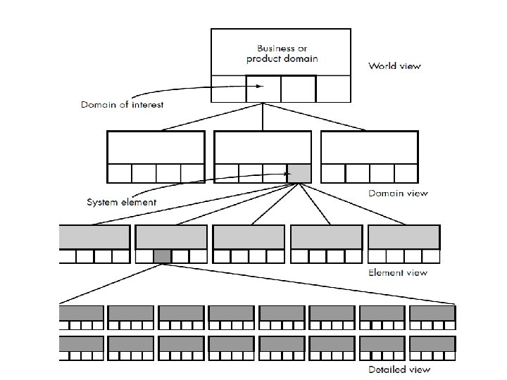
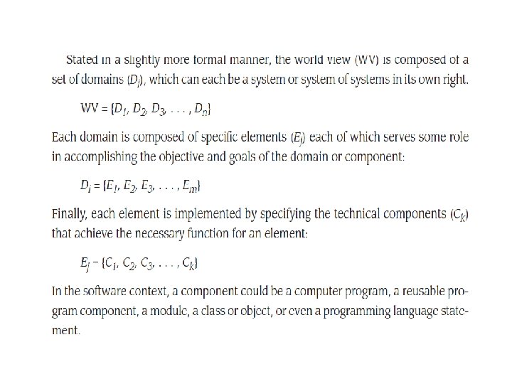
 System Engineering Process • The system engineering process begins with a world view; • the business or product domain is examined to ensure that the proper business or technology -established • The world view is refined to focus on a specific domain of interest • Within a specific domain, the need for targeted system elements is analyzed • Finally, the analysis, design, and construction of a targeted system element are initiated • At the world view level, a very broad context is established • At the bottom level, detailed technical activities are conducted by the relevant engineering discipline (e. g. , software engineering) 7
 System Engineering Hierarchy World View Domain View Element View Component View 8
 • Defines the processes (e. g. , domain") System Modeling (at each view level) • Defines the processes (e. g. , domain classes in OO terminology) that serve the needs of the view under consideration • Represents the behavior of the processes and the assumptions on which the behavior is based • Explicitly defines intra-level and inter-level input that form links between entities in the model • Represents all linkages (including output) that will enable the engineer to better understand the view • May result in models that call for one of the following – Completely automated solution – A semi-automated solution – A non-automated (i. e. , manual) approach 11
System Modeling (at each view level) • Defines the processes (e. g. , domain classes in OO terminology) that serve the needs of the view under consideration • Represents the behavior of the processes and the assumptions on which the behavior is based • Explicitly defines intra-level and inter-level input that form links between entities in the model • Represents all linkages (including output) that will enable the engineer to better understand the view • May result in models that call for one of the following – Completely automated solution – A semi-automated solution – A non-automated (i. e. , manual) approach 11
 Factors -when Constructing a Model • Assumptions – reduce the number of possible variations, thus enabling a model to reflect the problem in a reasonable manner • Simplifications – These enable the model to be created in a timely manner • Limitations – These help to bound the maximum and minimum values of the system • Constraints – These guide the manner in which the model is created and the approach taken when the model is implemented • Preferences – These indicate the preferred solution for all data, functions, and behavior – They are driven by customer requirements 12