

45f33f34c51f1592bc0ef36e0b0e0175.ppt
- Количество слайдов: 29
 SESSION ACCELERATEURS 10 -15 participants au groupe de travail 3 exposés 1 invité Arguments : 1) Accélération laser-plasma 2) Futurs collisioneurs 3)Technologie des accélérateurs
 Variola, R. Roux, S. Cavalier, M. Omeich, B. Mouton, G. Bienvenu, J. Brossard, H. Jenhani, P. Puzo, P. Bambade, O. Dadoun, C. Rimbault Accelerator Physics : Future Colliders
 ILC 2) CLIC 3)") New Prospects in the field of future colliders : 1) ILC 2) CLIC 3) Super. B These machines do not yet exist. They are already projected in the future… (near? Far? )
New Prospects in the field of future colliders : 1) ILC 2) CLIC 3) Super. B These machines do not yet exist. They are already projected in the future… (near? Far? )
 all") Why a linear collider? Particle physics colliders to date have (at my knowledge) all been circular machines (with the exception – SLAC SLC). Highest energy e+e- collider was LEP 2: ECM=200 Ge. V High energy in a circular machine becomes prohibitive large power or huge tunnels (and tech. problems as e- cloud, desorption…etc) ILC cost Energy increases at given radius DE ~ E 4/r (synchrotron radiation) e. g. LEP DE = 4 Ge. V/turn; P~20 MW Circular Collider Linear Collider Energy
Why a linear collider? Particle physics colliders to date have (at my knowledge) all been circular machines (with the exception – SLAC SLC). Highest energy e+e- collider was LEP 2: ECM=200 Ge. V High energy in a circular machine becomes prohibitive large power or huge tunnels (and tech. problems as e- cloud, desorption…etc) ILC cost Energy increases at given radius DE ~ E 4/r (synchrotron radiation) e. g. LEP DE = 4 Ge. V/turn; P~20 MW Circular Collider Linear Collider Energy
 • ILC
• ILC
 The ILC : concept Beams with energy tuneable up to 250 Ge. V (upgrade to 500 Ge. V); Two identical linear several km long linacs. 90% polarised electron source; positrons formed by g’s creating e+-e- pairs (possibly polarisation 60%). Damping rings to produce very small emittance beams. Final focus to collide nanobeams (crossing angle? ).
 ~50 km (1 Te. V) 2 x") ILC layout ~30 km (500 Ge. V) ~50 km (1 Te. V) 2 x 250 Ge. V linear accelerators ECM < 500 Ge. V, 20 mrad crossing angle. Cold technology : SC cavities Positrons made from g’s (can be polarized) striking a conversion target. Two interaction points. Using backscattered laser light 0 ption for a g-g collider. Option for a low energy collision region (Giga. Z)
ILC layout ~30 km (500 Ge. V) ~50 km (1 Te. V) 2 x 250 Ge. V linear accelerators ECM < 500 Ge. V, 20 mrad crossing angle. Cold technology : SC cavities Positrons made from g’s (can be polarized) striking a conversion target. Two interaction points. Using backscattered laser light 0 ption for a g-g collider. Option for a low energy collision region (Giga. Z)
 ILC Challenges => A lot, but we can divide them in two categories : 1 ) Technology Bunch train length 950 ms 2) Scheme and machine physics Train rep rate 5 Hz Beam height at collision 6 nm Beam width at collision 540 nm Accel. Gradient 31. 5 MV/m Wall plug effic. 23% L=2 x 1034 cm-2 s-1 Site power (500 Ge. V) 140 MW
 High Power Couplers (see R. Roux talk) 2) Polarised") ILC @ LAL : 1) High Power Couplers (see R. Roux talk) 2) Polarised Positron Source & Polarimeter 3) Interaction point studies
ILC @ LAL : 1) High Power Couplers (see R. Roux talk) 2) Polarised Positron Source & Polarimeter 3) Interaction point studies
 The alternative solution : “Compton Ring” 1)The idea comes from") Polarised Positron Source (POSIPOL) The alternative solution : “Compton Ring” 1)The idea comes from LAL (K. Moenig) 2)A community is working covering a lot of different activities ( Fabry-Perot cavities, Compton simulations, Optimisation of the collection system, …. ) 3)We promote the first “POSIPOL” workshop 4)We are working to propose a definitive scheme based on low repetition frequency, high duty cycle, less cavities (interaction points)
Polarised Positron Source (POSIPOL) The alternative solution : “Compton Ring” 1)The idea comes from LAL (K. Moenig) 2)A community is working covering a lot of different activities ( Fabry-Perot cavities, Compton simulations, Optimisation of the collection system, …. ) 3)We promote the first “POSIPOL” workshop 4)We are working to propose a definitive scheme based on low repetition frequency, high duty cycle, less cavities (interaction points)
 Electron Energy (Ge. V)") Polarised positron source : Snowmass Proposal Electron Beam (Compton Ring) Electron Energy (Ge. V) Ne-/bunch Spot Size at CP (micron) Circumferences (m) Number of Bunches Number of Trains 4. 1 6. 3 x 10 10 5(h)x 25(v) 649. 4 280 x 2 2 1. 3 6. 3 x 10¹⁰ 5(h)x 25(v) 276. 7 280 1 Laser Beam Photon Energy (e. V) Pulse Energy/bunch(m. J) Spot Size at CP (micron) 0. 117 210 25(h)x 25(v) 1. 16 590 5(h)x 5(v) Gamma-rays Energy(Me. V) 23 -29 Very interesting and multidisciplinary activity: machine physics, radiation theory, lasers and cavities, positron production and mechanisms of polarisation propagation…… It is a huge, self standing project!!!!
Polarised positron source : Snowmass Proposal Electron Beam (Compton Ring) Electron Energy (Ge. V) Ne-/bunch Spot Size at CP (micron) Circumferences (m) Number of Bunches Number of Trains 4. 1 6. 3 x 10 10 5(h)x 25(v) 649. 4 280 x 2 2 1. 3 6. 3 x 10¹⁰ 5(h)x 25(v) 276. 7 280 1 Laser Beam Photon Energy (e. V) Pulse Energy/bunch(m. J) Spot Size at CP (micron) 0. 117 210 25(h)x 25(v) 1. 16 590 5(h)x 5(v) Gamma-rays Energy(Me. V) 23 -29 Very interesting and multidisciplinary activity: machine physics, radiation theory, lasers and cavities, positron production and mechanisms of polarisation propagation…… It is a huge, self standing project!!!!
 @LAL Capture Cavities Int. Point
 Very complex scheme…. in continuous evolution => LAL PROSPECTS => Playing a leading role in conceiving the right scheme and in developing the technology for the Fabry-Perot Cavity. Optimisation of the collection and of the positron production. Analysis of the polarisation issue. Example: scheme for the Nd-Yag laser
 Interaction region background studies in e+ e- collider When beams collide: mixing of classical and quantum effects • • • Bunches deformed by EM attraction: Disruption luminosity enhancement High beam-beam field Energy loss in the form of synchrotron radiation: beamstrahlung Secondary backgrounds Electromagnetic : e+ + e- → gg → e+e- … Hadronic : e+ + e- → gg → hadrons • After the collision: disrupted beam induces backgrounds (photons, pairs, neutrons. . . ) Electromagnetic deflections Effect on backgrounds (pairs. . . ) Effect on luminosity measurements (Bhabha scattering) • e+ è GUINEA-PIG & CAIN: beam-beam simulation tools e- spin depolarisation effects • Possible damage of beam magnets in the extraction beam line • Backscattering of background particles in the detector è BDSIM based on GEANT 4: uses to evaluate backgrounds generated along the extraction line
 x & y emittances (ILC) x") Ex: ILC & Super B studies (C. Rimbault) x & y emittances (ILC) x & y emittances super. B Biagini Pair phase space Vertex Detector background for 3, 4 and 5 T Bhabha focusing versus production angle q 0 (mrad)
Ex: ILC & Super B studies (C. Rimbault) x & y emittances (ILC) x & y emittances super. B Biagini Pair phase space Vertex Detector background for 3, 4 and 5 T Bhabha focusing versus production angle q 0 (mrad)
 Future Extend Guinea. Pig, beam-beam interaction simulation code for linear colliders, to circular colliders. Customize the existing neutron propagation in GEANT 4. Finalizing procedure for submitting our softwares on GRID LCG/EGEE (under ILC virtual organization) and Xtrem. Web.
 • CLIC
 • High acceleration gradient (150 MV/m) • “Compact” collider") CLIC @ CERN (relativistic Klystron) • High acceleration gradient (150 MV/m) • “Compact” collider - overall length 40 km • NC accelerating structures • High frequency (30 GHz) • Two-Beam Acceleration Scheme (Relativistic Klystron) • High frequency • Cost-effective & efficient (~ 10% overall)
CLIC @ CERN (relativistic Klystron) • High acceleration gradient (150 MV/m) • “Compact” collider - overall length 40 km • NC accelerating structures • High frequency (30 GHz) • Two-Beam Acceleration Scheme (Relativistic Klystron) • High frequency • Cost-effective & efficient (~ 10% overall)
 Philosophy The RF power source can be described as a blind box combining very long RF pulses, and transforming them in many short pulses, with higher power and with higher frequency 350 Klystrons Power stored in electron beam Power extracted from beam in resonant structures low frequency high efficiency Long RF Pulses P 0 , n 0 , t 0 48000 Accelerating Structures high frequency high gradient Electron beam manipulation Short RF Pulses PA = P 0 N t. A = t 0 / N f. A = f 0 N R. Corsini
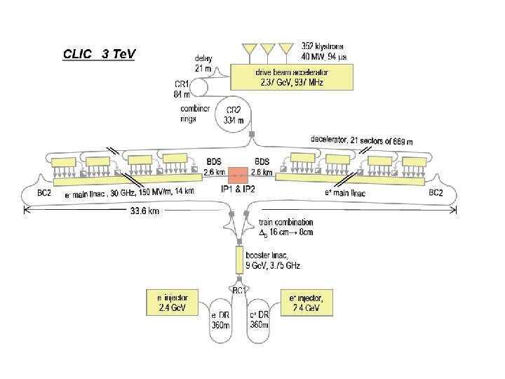
 CLIC Parameters @ 3 Te. V Center of mass energy Ecm 3000 Ge. V Main Linac RF Frequency f. RF 30 GHz Luminosity L 6. 5 1034 cm-2 s-1 Luminosity (in 1% of energy) L 99% 3. 3 1034 cm-2 s-1 Linac repetition rate frep 150 Hz No. of particles / bunch Nb 2. 56 109 No. of bunches / pulse kb 220 Bunch separation Δtb 0. 267 (8 periods) ns Bunch train length τtrain 58. 4 ns Pb 20. 4 MW Unloaded / loaded gradient Gunl/l 172 / 150 MV/m Overall two linac length llinac 28 km Total beam delivery length l. BD 2 x 2. 6 km Proposed site length ltot 33. 2 km Total site AC power Ptot 418 MW Wall plug (RF) to main beam power efficiency ηtot 12. 5 % Beam power / beam
 project : photo-injector") LAL – Now CTF 3 2004: Start of the PHIN (CARE) project : photo-injector for the CERN ( and another similar one for machine studies at LAL) Motivations: -High charge per pulse -Short pulses -Little emittances + easy to transport -No low energy tails Competence: -Vacuum -Magnetic elements -HF Installation: end 2006
LAL – Now CTF 3 2004: Start of the PHIN (CARE) project : photo-injector for the CERN ( and another similar one for machine studies at LAL) Motivations: -High charge per pulse -Short pulses -Little emittances + easy to transport -No low energy tails Competence: -Vacuum -Magnetic elements -HF Installation: end 2006
 2005: Start of the test gun construction Goal: facility that simulate the principal beam at 30 GHz Installation: half 2007 … we hope Prospects @ SERA on CTF 3 1. CERN experiments participation 2. Modify or built another gun (if needed) 3. R&D on the HF gun @ LAL in the NEPAL hall (? ? ? ) - Weak emittance gun - High gradient - High repetition rate ( average current) And what about the far future (CLIC)? SOURCES 1) Injector e 2) Polarised Positron Source (F. Zimmermann)
 • SUPERB B
 Goal : 1036 Luminosity For the time being : crazy schemes & ideas main goal : reduce the power consumption !!!! Simplified layout in the Small Disruption Regime Collisions every Turn ILC ring with ILC FF ILC Compressor, Crossing angle optional Decompressor Compressor FF Decompressor I P FF Compressor
 An exemple of parameter set and solutions: • • • Flat case, Collisions in the Ring, Uncompressed Bunches Nbunches=5000, 3 Km ring Crab focus on in vertical plane X_crossing_angle=2*25 mrad sz=4 mm se=5 Me. V ex=0. 4 nm ey=0. 002 nm ez=4. 0 mm Collision frequency=500 MHz Lmultiturn=0. 8*1036 (Lsingleturn=1. 2*1036) with Np=2*1010 Vertical tune shift like in PEP!!! (similar currents, 100 times more luminosity, 100 times smaller betay) L=1. 6*1036 with Np=4*1010 Luminosity higher with further simultaneuos betax and betay squeeze A lot of work and ideas are still possible in the conception phase. Determinant is the study of the interaction point!!! So prospects @ LAL : interaction point studies & Positron source (conventional / Compton) &
 Conclusions • 3 main international collider projects : ILC, CLIC & Super. B • A lot of similarities between the different project and a lot of challenges • Prospects @ LAL: we have the possibility to give a significant contribution to the design and construction phase in the three projects • Specific topics are : positron sources (polarised and not), couplers, interaction point studies, photoguns, injectors. . . (in mixed order) • To reach this goal we need a close collaboration between the different LAL departments and. . .
 • Are these dreams? For real future prospects we need a strong accelerator group (as in the most important European Labs )! Because now the situation @ SERA: Logistics Personnel Technology Electronics
 Thanks very much to all the “ transparencies providers ”.