SEISMIC RESEARCH VESSELS Training program SEISMIC RESEARCH VESSELS


18708-seismic_research_vessels.ppt
- Количество слайдов: 23
 SEISMIC RESEARCH VESSELS Training program
 SEISMIC RESEARCH VESSELS CONTENTS. Purpose of seismic survey. Marine seismic methods: A. Underlying Principles; B. Towed Streamer Acquisition: 2D Seismic; 3D Seismic; Time Lapse (4D) Seismic; Sonar. C. Seafloor Acquisition; D. Borehole Acquisition; E. Seismic Energy Sources: Airgun; Sparker; Alternate Marine Seismic Sources. 3. Non-seismic methods: - A. Marine Magnetotellurics (MMT). - B. Gravity & Magnetic. C. Passive Acoustic Seismic. 4. Impacts of seismic survey on ocean life. 5. Protection of marine life during marine seismic survey. 6. POLARCUS class ships. 7. RAMFORM class ships
 PURPOSE OF SEISMIC SURVEY Seismic vessels are ships that are solely used for the purpose of seismic survey in the high seas and oceans. A seismic vessel is used as a survey vessel for the purpose of pinpointing and locating the best possible area for oil drilling in the middle of the oceans. Companies engaged in the oil drilling process make use of such vessels so that they find the best possible subsea areas to drill oil. Another major reason such seismic vessels are so important is that if oil drillers do not get the best subsea location to drill the oil and gas, then it could lead to dangerous and threatening consequences for the marine eco-system. The usage of the seismologic vessels prevents such inadvertent mistakes. Seismic Survey and Seismic Vessels For the purpose of seismic survey, seismic waves are the main components that are analysed. The process involves a seismic detector that shoots such seismic waves to a selected underwater point. The time taken for the waves to refract back to their origin point determines whether that particular subsea area is feasible for the oil drilling purpose A survey vessel is the one that helps monitor such seismic waves. It is the primary requirement for any shipping concern engaged in or planning to engage in the process of oil and gas excavation from the oceanic reservoirs. A seismic vessel is fitted with all technological gadgets like GPS, computers, nautical charts and any other equipment that would enhance the process of seismic survey. Such vessels are built very carefully and only in selected locations across the world. This is because the entire ship-building process for seismic vessel involves fitting all the necessary gadgets (mentioned above) without missing even a single one. Seismic vessels are more in demand in today’s time considering the amount of subsea drilling that is being carried out. They are also known as research vessels because in a completely different way, they do help research the oceans and seas. Additional Benefits In addition to being vessels that survey underwater seismology, seismic vessels are also used to study the geology of the oceans and seas. This aspect includes the formation of rocks, oceanic trenches and many other details that are important and could affect the lives of humans and marine creatures alike. Thus it can be seen that the main USP of seismic vessels lies in the fact that it helps not just scientists and researchers find out relevant oil and gas but also helps them to prevent any other major catastrophe in the form of natural calamities from occurring. Seismic survey is a must. In fact it can be said that every underwater operation requires a seismic survey with the help of seismic vessels. A seismic vessel is one of those technological developments that have the ability to enable more successes than failures in fields where losses are far more costly than wins. And for this purpose alone, a survey vessel can be regarded as the pride of modern technological invention and initiation.
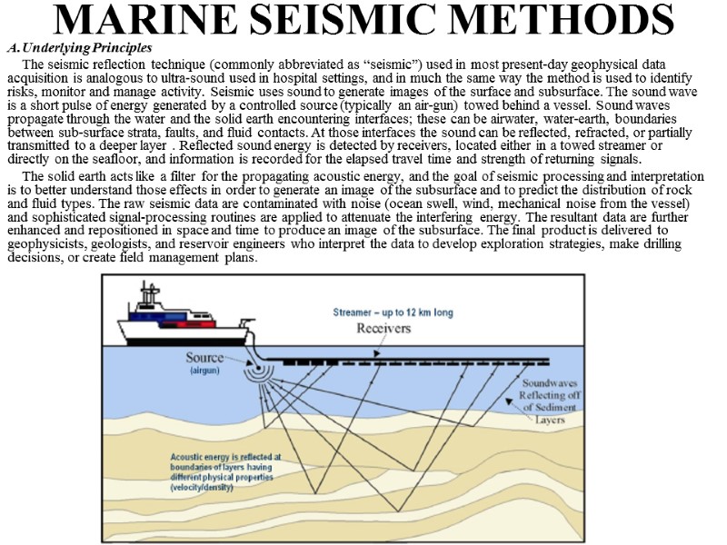
 MARINE SEISMIC METHODS Underlying Principles The seismic reflection technique (commonly abbreviated as “seismic”) used in most present-day geophysical data acquisition is analogous to ultra-sound used in hospital settings, and in much the same way the method is used to identify risks, monitor and manage activity. Seismic uses sound to generate images of the surface and subsurface. The sound wave is a short pulse of energy generated by a controlled source (typically an air-gun) towed behind a vessel. Sound waves propagate through the water and the solid earth encountering interfaces; these can be airwater, water-earth, boundaries between sub-surface strata, faults, and fluid contacts. At those interfaces the sound can be reflected, refracted, or partially transmitted to a deeper layer . Reflected sound energy is detected by receivers, located either in a towed streamer or directly on the seafloor, and information is recorded for the elapsed travel time and strength of returning signals. The solid earth acts like a filter for the propagating acoustic energy, and the goal of seismic processing and interpretation is to better understand those effects in order to generate an image of the subsurface and to predict the distribution of rock and fluid types. The raw seismic data are contaminated with noise (ocean swell, wind, mechanical noise from the vessel) and sophisticated signal-processing routines are applied to attenuate the interfering energy. The resultant data are further enhanced and repositioned in space and time to produce an image of the subsurface. The final product is delivered to geophysicists, geologists, and reservoir engineers who interpret the data to develop exploration strategies, make drilling decisions, or create field management plans.
 The solid earth acts like a filter for the propagating acoustic energy, and the goal of seismic processing and interpretation is to better understand those effects in order to generate an image of the subsurface and to predict the distribution of rock and fluid types. The raw seismic data are contaminated with noise (ocean swell, wind, mechanical noise from the vessel) and sophisticated signal-processing routines are applied to attenuate the interfering energy. The resultant data are further enhanced and repositioned in space and time to produce an image of the subsurface. The final product is delivered to geophysicists, geologists, and reservoir engineers who interpret the data to develop exploration strategies, make drilling decisions, or create field management plans. Geophysical technologies have been a critical tool in hydrocarbon exploration since the early part of the 20th century. Prior to the mid-1980s, the majority of seismic data collected in offshore settings were two-dimensional (2D), meaning they defined a plane where the seismicderived structure (depth of the plane) pertained to a single surface traverse (edge of the plane). Since that time, techniques to assemble three-dimensional (3D) seismic data were developed by integrating multiple 2D planes (as multiple surface traverses) into projection of a 3D volume. Currently, 3D seismic has become the standard tool for exploration and development, especially in the Gulf of Mexico. In an exploration context, seismic data are used to identify regions or geologic trends which have higher potential for commercial resources, with the ultimate goal being to reduce the amount of wildcat drilling necessary to successfully locate economic reserves. Once a prospect has been identified, seismic is a critical tool to identify potential drilling hazards. During the production phase, time-lapsed 3D seismic acquired over months or years (commonly called 4D seismic in recognition of the time dimension), can be a critical tool for understanding the effectiveness of the development strategy and allow for adjustments to maximize production from existing wellbores, potentially eliminating the need for additional drilling. Geophysical technologies are also critical to the advance of Earth science. In the last several decades, efforts to understand the natural forces that shape and change our planet have accelerated rapidly, particularly in the field of marine geophysics, where researchers use advanced technology to probe deep beneath the oceans and observe Earth's interior. Here we have records of sea-level rise that are key to understanding global climate change, clues about fault behavior that lead to great tsunami-generating earthquakes, and structures that might contain new hydrocarbon resources (LDEO, 2006). The following sections will briefly review the main types of seismic surveys currently used in both energy exploration and scientific research applications (summarized in Table 1). An additional review of current methods and principles is available from the International Association of Geophysical Contractors (IAGC, 2009) and the National Science Foundation (NSF) and US Geological Survey (USGS) Draft Programmatic Environmental Impact Statement (PEIS) for marine seismic research (NSF and USGS, 2010). MARINE SEISMIC METHODS
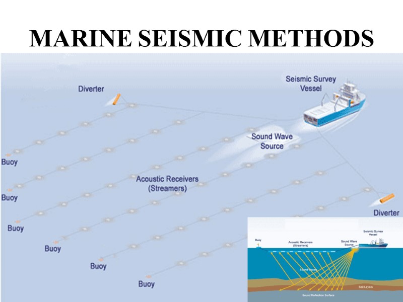
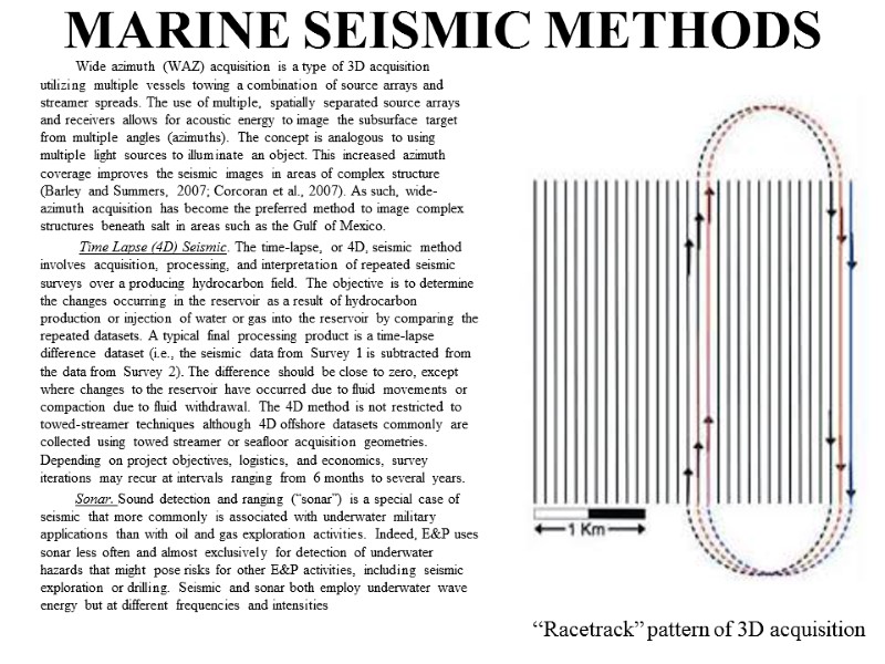
 B. Towed Streamer Acquisition Towed streamer acquisition consists of one or more marine vessels behind which are towed one or more streamers and seismic source arrays. The acquisition parameters (length, depth, separation, volume, data record length) depend on the objectives of each survey that, in turn, are functions of the geophysical requirements to correctly image the target. 2D Seismic. In 2D operations a single streamer is towed behind the survey vessel together with a single sound source. Typically, 2D surveys are conducted in frontier regions where no dataset exists and provide a sparsely sampled series of sub-surface images. Those images are used to identify play types and gross structural features, but are generally considered insufficient for detailed reservoir-scale evaluation. A 2D survey is almost exclusively used for exploration. Because of the 2D nature of the acquisition, energy from reflection interfaces outside the plane of the section cannot be properly processed and can interfere with the quality of resultant image. 3D Seismic. 3D seismic is acquired by towing a series of streamers behind a vessel with either one or two sound sources. The streamers are separated in a pattern similar to prongs on a rake; the separation depends of the geophysical requirements of the survey but typically ranges from 50 to 150 meters. A survey area is defined that is large enough to image the area of interest, as well as halo of data around the target(s), which is necessary to properly process the data. The seismic vessel acquires the data in a lawn-mower pattern with adjacent lines, or in a race-track pattern that slowly works across the entire area until all the survey is complete . A 3D survey can range in size from a few hundred square surface kilometers, taking a few weeks to acquire, up to ten thousand square surface kilometer surveys that can take many months. A completed 3D survey consists of a true three-dimensional volume of data which can be ‘sliced’ or viewed in whatever orientation is appropriate for the objectives of the interpreter. MARINE SEISMIC METHODS
 MARINE SEISMIC METHODS
 Wide azimuth (WAZ) acquisition is a type of 3D acquisition utilizing multiple vessels towing a combination of source arrays and streamer spreads. The use of multiple, spatially separated source arrays and receivers allows for acoustic energy to image the subsurface target from multiple angles (azimuths). The concept is analogous to using multiple light sources to illuminate an object. This increased azimuth coverage improves the seismic images in areas of complex structure (Barley and Summers, 2007; Corcoran et al., 2007). As such, wide-azimuth acquisition has become the preferred method to image complex structures beneath salt in areas such as the Gulf of Mexico. Time Lapse (4D) Seismic. The time-lapse, or 4D, seismic method involves acquisition, processing, and interpretation of repeated seismic surveys over a producing hydrocarbon field. The objective is to determine the changes occurring in the reservoir as a result of hydrocarbon production or injection of water or gas into the reservoir by comparing the repeated datasets. A typical final processing product is a time-lapse difference dataset (i.e., the seismic data from Survey 1 is subtracted from the data from Survey 2). The difference should be close to zero, except where changes to the reservoir have occurred due to fluid movements or compaction due to fluid withdrawal. The 4D method is not restricted to towed-streamer techniques although 4D offshore datasets commonly are collected using towed streamer or seafloor acquisition geometries. Depending on project objectives, logistics, and economics, survey iterations may recur at intervals ranging from 6 months to several years. Sonar. Sound detection and ranging (“sonar”) is a special case of seismic that more commonly is associated with underwater military applications than with oil and gas exploration activities. Indeed, E&P uses sonar less often and almost exclusively for detection of underwater hazards that might pose risks for other E&P activities, including seismic exploration or drilling. Seismic and sonar both employ underwater wave energy but at different frequencies and intensities MARINE SEISMIC METHODS “Racetrack” pattern of 3D acquisition
 C. Seafloor Acquisition Receivers can also be deployed directly on the seafloor, as opposed to being located within a towed streamer. Seafloor acquisition is typically more costly than towed streamer acquisition because the process of deploying and recovering receivers requires more complex efforts but is generally used in shallow water or areas with numerous surface obstructions (e.g., platforms) where towed-streamer acquisition is difficult or impossible. Additional benefits of seafloor acquisition which can favor the use of these technologies in some situations include (1) the ability to measure shear wave data, and (2) the ability to accurately replicate receiver locations for 4D surveys. Two general types of seafloor acquisition are currently in use: ocean bottom cable (OBC) and seafloor node. For both types, the acoustic source is towed behind a surface vessel like in towed streamer acquisition. In OBC acquisition, receivers are located inside cables up to several kilometers long which are deployed and recovered from a surface vessel. OBC surveys can either be 2D (single cable), or more commonly 3D (multiple cables). Seafloor node acquisition uses receivers which are placed directly on the seafloor, generally by ROVs. The nodes are typically recovered after acquisition, although ‘permanent’ node installations have been tested. Unlike OBC surveys where the receiver spacing and acquisition geometry is controlled by cable deployment, seafloor nodes can be deployed in whatever spacing and geometry provides for optimal subsurface imaging characteristics. Node surveys are also practical in deep water settings, unlike OBC surveys. MARINE SEISMIC METHODS
 D. Borehole Acquisition Geophysical data acquired at a well location, either a vertical seismic profile (VSP) or checkshot survey, are used to provide a better tie between conventional seismic data and the well, and also to provide detailed information about the geology and reservoir characteristics in the vicinity of the borehole. Seismic receivers are lowered into the borehole as part of a wireline assembly and the acoustic source is located in the water column at or near the well location. There are five main classes of borehole geophysical data: (1) check-shot survey, (2) zero-offset VSP, (3) walkaway VSP, (4) 3D VSP, and (5) cross-well seismic (or electromagnetic) data. For check-shot and zero-offset VSP data, the source is located at the drill site, with the difference being greater vertical sampling for a zero-offset survey. For more detailed subsurface information, the source is towed away from the wellsite to provide greater offset between source and receiver. In a 3D VSP, the source is towed in a 3D grid around the well, while for a walkaway VSP the source is towed in one or more 2D traverses. In cross-well acquisition, the source and receivers are located in nearby wellbores, with the goal to produce an image of the subsurface between well locations. MARINE SEISMIC METHODS
 E. Seismic Energy Sources The goal of the seismic source is to create a sound wave that can travel through the water and sub-surface to reach the target with enough return energy to be recorded at the surface. Ideally the source should be repeatable, reliable, with a high signal to noise ratio and high resolution. In the early years of offshore seismic exploration a single explosive charge (dynamite) was the most commonly used source of seismic energy. The use of explosives became intolerable as they risked worker safety and could obviously damage reefs and kill marine life. Subsequently many types of marine seismic sources were developed and used, some more successfully than others, including the airgun, sparker, boomer, maxi-pulse, gas-gun, water-gun, flexitor, detonating cord, steam-gun, flexichoc, and marine vibroseis (Evans, 1997). Presented here is a review of current technology and how it is deployed in the field. Seismic surveys typically target reservoirs many thousands of feet beneath the surface of the solid earth and it is important to deploy a source that can generate enough energy to fully image the target. Energy is lost as the sound wave propagates through the Earth. The high-frequency component of the signal attenuates more rapidly, leading to generally decreasing resolution with depth. The choice of seismic source(s) for a specific survey should be based on the objectives of the survey. MARINE SEISMIC METHODS
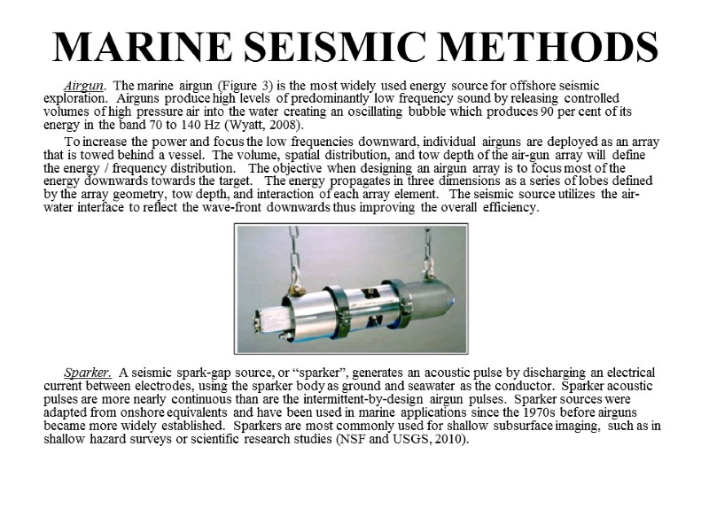
 Airgun. The marine airgun (Figure 3) is the most widely used energy source for offshore seismic exploration. Airguns produce high levels of predominantly low frequency sound by releasing controlled volumes of high pressure air into the water creating an oscillating bubble which produces 90 per cent of its energy in the band 70 to 140 Hz (Wyatt, 2008). To increase the power and focus the low frequencies downward, individual airguns are deployed as an array that is towed behind a vessel. The volume, spatial distribution, and tow depth of the air-gun array will define the energy / frequency distribution. The objective when designing an airgun array is to focus most of the energy downwards towards the target. The energy propagates in three dimensions as a series of lobes defined by the array geometry, tow depth, and interaction of each array element. The seismic source utilizes the air-water interface to reflect the wave-front downwards thus improving the overall efficiency. Sparker. A seismic spark-gap source, or “sparker”, generates an acoustic pulse by discharging an electrical current between electrodes, using the sparker body as ground and seawater as the conductor. Sparker acoustic pulses are more nearly continuous than are the intermittent-by-design airgun pulses. Sparker sources were adapted from onshore equivalents and have been used in marine applications since the 1970s before airguns became more widely established. Sparkers are most commonly used for shallow subsurface imaging, such as in shallow hazard surveys or scientific research studies (NSF and USGS, 2010). MARINE SEISMIC METHODS
 Alternate Marine Seismic Sources. Two reports have been produced on acoustic and non-acoustic alternatives to existing seismic sources (Spence et al., 2007; Weilgart, 2010), with the aim of identifying technologies that can reduce environmental impacts. Much hope has been placed on the development of marine vibrator technology which the offshore industry developed from the land equivalent. Initial development started in the 1970s and continued into the 1980s. Those initial efforts were eventually abandoned due to engineering obstacles and cost constraints when compared to airguns. Early field tests noted reduced data quality at deep (> 3 seconds two-way travel time) target depths due to limitations in the low-frequency portion of the source spectrum (Haldorsen et al., 1985). In recent years several companies and an industry consortium have taken up the challenge once more in an attempt to produce an alternate marine seismic source that can be tuned to specific geophysical objectives and reduce unwanted noise. Initial results of those efforts have resulted in prototype marine vibrators capable of energy output down to 6 Hz (Weilgart, 2010). The marine vibrator consists of an acoustic housing (analogous to a speaker) containing either a hydraulically or electrically driven oscillator. The oscillator is driven at various frequencies (sweep) causing expansion and contraction of the housing that generates sound waves. The advantage of this technology is two-fold: (1) controllable frequency range, and (2) coding of the sound waves (phase) that could allow for simultaneous acquisition (multiple sources). Target applications of marine vibrators currently in development include shallow water acquisition, seismic monitoring, and environmentally sensitive areas (Weilgart, 2010). Other technological alternatives discussed by the two reports (Spence et al., 2007; Weilgart, 2010) include deep-towed acoustic/geophysics system (DTAGS) and low-frequency acoustic source (LACS) and the non-acoustic systems surveyed below. MARINE SEISMIC METHODS
 NON-SEISMIC METHODS Non-active acoustic geophysical methods employed in hydrocarbon exploration include (1) controlled-source electromagnetic (CSEM), (2) marine magnetotelluric (MMT), (3) gravity, (4) magnetic, and (5) passive acoustic surveys. Each of these methods has specific exploration applications, but currently they are most often used as complementary technologies to seismic. Controlled-Source Electromagnetics (CSEM). Reviews of the history, development, and applications of CSEM can be found in Constable (2010), Constable and Srnka (2007), and Edwards (2005). CSEM surveys measure resistivity contrasts in the subsurface in response to an induced electrical field. Electrical receivers, attached to standard or degradable concrete anchors, are deployed on the seafloor. The number of receivers employed will vary from one project to another, depending on imaging objectives and budgetary constraints. An electrical dipole transmitter, deployed from a surface vessel, is towed at a distance of between 10-100 meters above the seafloor. After data acquisition, the receivers are remotely released from their anchors and rise back to the surface where they are retrieved by the survey vessel. Because hydrocarbon-charged sediments have higher electric resistivity than those filled with saline formation waters, CSEM surveys have the potential to aid in the identification of subsurface oil and gas accumulations. Resistivity measurements are used extensively in wireline logging applications for the identification of reservoir intervals in boreholes, but CSEM surveys allow for the collection of resistivity measurements on a much larger scale and thus can be appropriate in an exploration context. Several published examples in recent years have illustrated the potential of the technology, when combined with other types of data, to reduce uncertainty ahead of drilling (e.g., Lovatini et al., 2009; Hesthammer et al., 2008). The technique, however, does have several important limitations. The presence of other large, highly-resistive bodies, such as salt diapirs/sheets or volcanic layers, can mask the response from hydrocarbon-filled reservoirs. Additionally, CSEM surveys do not currently provide the degree of spatial resolution possible from modern seismic data (Constable, 2010). Finally, because of interference caused by the strong resistivity contrast at the air/water interface, CSEM surveys are generally more effective in water depths over 500 meters, although careful processing of the data can often mitigate this issue (Constable and Srnka, 2007; Hesthammer et al., 2010).
 Marine Magnetotellurics (MMT). Like CSEM surveys, MMT surveys attempt to measure the resistivity structure of the subsurface, but use naturally occurring electrical currents induced by variations in the Earth’s magnetic field instead of a towed source (Constable et al., 1998; Sandberg et al., 2008). MMT surveys employ the same type of receivers used for CSEM surveys, but because of the weaker (and variable) nature of the natural source, the receivers are typically left on the seafloor for up to several days (Hoversten et al., 2000). Because of the poor vertical and lateral resolution of the data (e.g., Hoversten, et al., 1998), MMT surveys are not used to directly identify potential hydrocarbon traps or accumulations, but have shown to be useful in delineating the extent of large resistive bodies such as salt sheets or diapirs. In areas of poor subsalt seismic data quality, MMT data have shown promise in helping (generally in conjunction with gravity data) to constrain the location of the base of salt which can result in improvement of the subsalt seismic image (Hoversten et al., 1998; Sandberg et al., 2008). Gravity & Magnetic. Reviews of the history and use of gravity and magnetic surveys in petroleum exploration may be found in Nabighian et al. (2005a,b), respectively. Neither method provides the vertical or lateral resolution necessary to identify or map potential hydrocarbon accumulations directly, but both methods can provide valuable information regarding the distribution of salt and the configuration of deep basin structural elements. As such, they often times play an important role in developing regional-scale basin models which can help focus exploration efforts, particularly in frontier or under-explored basins. Gravity data, in conjunction with seismic data, also are used to help constrain resistivity models in MMT surveys in a process known as simultaneous joint inversion (Virgilio et al., 2010). NON-SEISMIC METHODS
 Passive Acoustic Seismic. Seismic exploration as discussed above is an active-acoustic approach in which seismic waves are artificially generated as the source of the sounding analysis. But the technologies used for active seismic exploration are relevant to passive monitoring, except there is no propagation of sound emanating from the Passive Acoustic Seismic devices. The Passive Acoustic Seismic approach consists of seismic-type detectors thatlisten for naturally occurring seismic or other acoustic energy (Nieukirk et al., 2004). Natural geologic processes that generate subsea seismic waves include volcanic eruptions, earthquakes and underwater landslides although the most typical context for Passive Acoustic Seismic pertains to listening for vocalizations of marine fauna, including whales. The latter application, which is used most often for detection of marine mammals (IAGC, 2009), normally is called Passive Acoustic Monitoring (PAM). NON-SEISMIC METHODS
 IMPACTS OF SEISMIC SURVEYS ON OCEAN LIFE WHAT ARE THE IMPACTS OF SEISMIC SURVEYS ON OCEAN LIFE? Current research indicates that there is minimal risk of mortality in marine mammals, fish and invertebrates when the sound energy of seismic surveys is released into the water column, and additional research is ongoing. Marine mammals, depending on the species and proximity to the seismic survey, can experience temporary changes to their hearing thresholds and in some extreme cases of unmitigated exposure, these effects can be permanent. Similarly, laboratory research has shown some physiological responses in invertebrates – crab, shrimp, scallop etc. More research will broaden our understanding of the potential impacts of seismic surveys. The industry is committed to ongoing research and to employing mitigation measures to minimize the impact on marine life.
 PROTECTION OF MARINE LIFE DURING MARINE SEISMIC SURVEYS HOW DO OFFSHORE OIL AND GAS COMPANIES WORK TO PROTECT MARINE LIFE DURING MARINE SEISMIC SURVEYS? Before a company can perform a marine seismic survey it must first undertake a thorough Environmental Assessment (EA), which reviews potential environmental impacts in the proposed survey area along with feedback from the public and marine stakeholders. The EA is reviewed by the Department of Fisheries and Oceans (DFO) and the Department of Environment and Climate Change, and must be approved by the Canada-Newfoundland and Labrador Offshore Petroleum Board (C-NLOPB) or the Canada-Nova Scotia Offshore Petroleum Board (CNSOPB) before a survey can proceed. Additionally, seismic survey operator must comply with guidelines established by the C-NLOPB and CNSOPB. Seismic vessels and their operators are also guided by DFO’s Statement of Canadian Practice with Respect to the Mitigation of Seismic Sound in the Marine Environment, which includes the following measures to be considered in planning and implementing seismic surveys: - Minimizing the sound energy employed to achieve the purpose of the survey; - Gradual start-up of a sound source to allow marine mammals, sea turtles and other species to move away; - Immediate shut down of sound sources if marine mammals or sea turtles listedas endangered are observed within 500 metres of the sound source; - Use of qualified observers to monitor survey operations; - Avoidance of known, critical habitats specified under species-at-risk legislation; - Avoidance of known species migration routes, spawning areas and habitats.
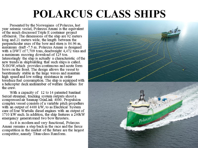
 POLARCUS CLASS SHIPS Presented by the Norwegians of Polarcus, last year seismic vessel, Polarcus Amani is the equivalent of the much discussed Triple E container project ofMaersk. The dimensions of the ship are 92 meters long and 21 meters wide, the length between the perpendicular axes of the bow and stern is 84.96 m, maximum draft -7.5 m. Polarcus Amani is designed with a DWT of 7,709 tons, deadweight 4,472 tons and a maximum mooring download of 125 ton. Interestingly the ship is actually a characteristic of the new trends in shipbuilding that such ships is called. X-BOW,which provides continuous and acute form bows on the front. The design allows the vessel to beextremely stable in the large waves and maintain high speed and low rolling resistance in order toreduce fuel consumption. The ship is equipped with a helicopter deck andnumber of welfare facilities for the crew. With a capacity of 12 to 14 patented Sentinel Sercel streamer, tracking system outputs shoot a compressed air Seamap GunLink 4000. Propulsion complex vessel consists of a variable pitch propellers with an output of 4400 kW, to as Electrical System care of four Wartsila diesel engines with an output of 1710 kW each. In addition, the ship features a 240kW emergency generatorand two bow thrusters. As it is modern and very functional, Polarcus Amani remains a step back in the race and the fierce competition in the market of the future are the largest competitor, namely Titan-class Ramform.
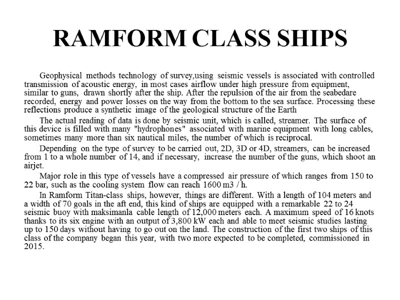
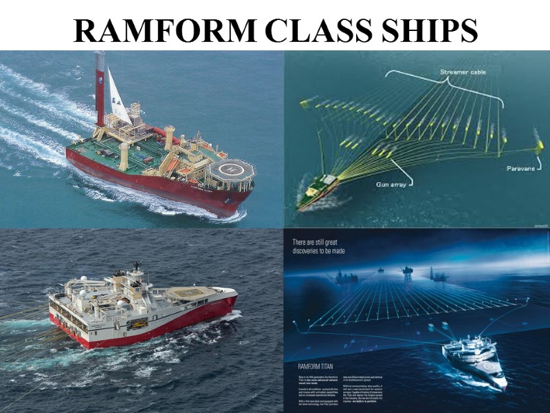
 Geophysical methods technology of survey,using seismic vessels is associated with controlled transmission of acoustic energy, in most cases airflow under high pressure from equipment, similar to guns, drawn shortly after the ship. After the repulsion of the air from the seabedare recorded, energy and power losses on the way from the bottom to the sea surface. Processing these reflections produce a synthetic image of the geological structure of the Earth The actual reading of data is done by seismic unit, which is called, streamer. The surface of this device is filled with many "hydrophones" associated with marine equipment with long cables, sometimes many more than six nautical miles, the number of which is reciprocal. Depending on the type of survey to be carried out, 2D, 3D or 4D, streamers, can be increased from 1 to a whole number of 14, and if necessary, increase the number of the guns, which shoot an airjet. Major role in this type of vessels have a compressed air pressure of which ranges from 150 to 22 bar, such as the cooling system flow can reach 1600 m3 / h. In Ramform Titan-class ships, however, things are different. With a length of 104 meters and a width of 70 goals in the aft end, this kind of ships are equipped with a remarkable 22 to 24 seismic buoy with maksimanla cable length of 12,000 meters each. A maximum speed of 16 knots thanks to its six engine with an output of 3,800 kW each and able to meet seismic studies lasting up to 150 days without having to go out on the land. The construction of the first two ships of this class of the company began this year, with two more expected to be completed, commissioned in 2015. RAMFORM CLASS SHIPS
 RAMFORM CLASS SHIPS
 CONTROL QUESTIONS. What is a purpose of seismic survey? Which marine seismic methods of survey do you know? What are the underlying principles of seismic survey? What is Towed Streamer Acquisition? Which kinds of Towed Streamer Acquisition do you know? What is Seafloor Acquisition? What is Borehole Acquisition? Which Seismic Energy Sources do you know? Which Non-seismic methods do you know? Which impacts of seismic survey on ocean life affect? Which kinds of protection of marine life during marine seismic survey can be used? SEISMIC RESEARCH VESSELS
 BIBLIOGRAPHY. OFFSHORE ENVIRONMENTAL MANAGEMENT OF SEISMIC AND OTHER GEOPHYSICAL EXPLORATION WORK. Working Document of the NPC North American Resource Development Study Made Available September 15, 2011 Submitted by Captain Oleh Tovstokoryi SEISMIC RESEARCH VESSELS

