Применение РЗ-материалов.ppt
- Количество слайдов: 31
 РЗЭ-содержащие магнитные материалы и их техническое применение
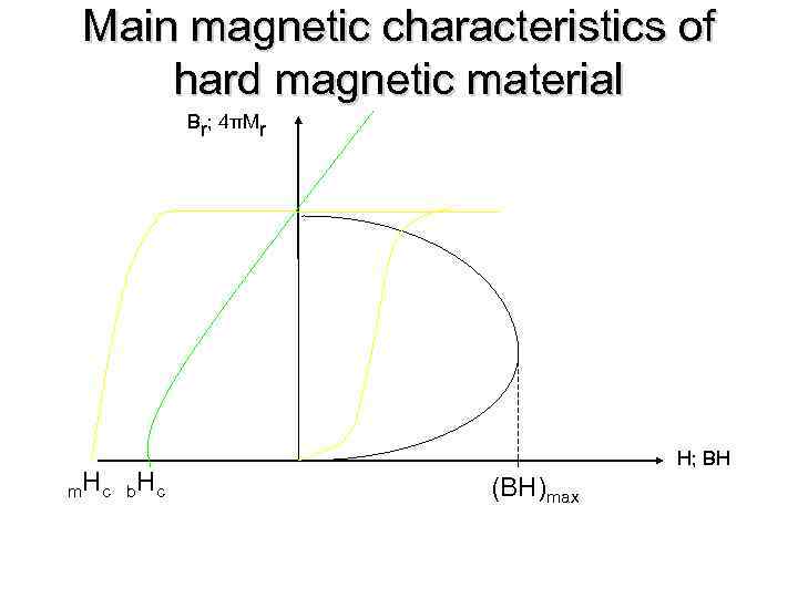 Main magnetic characteristics of hard magnetic material Br; 4πMr m. H c b H c H; BH (BH)max
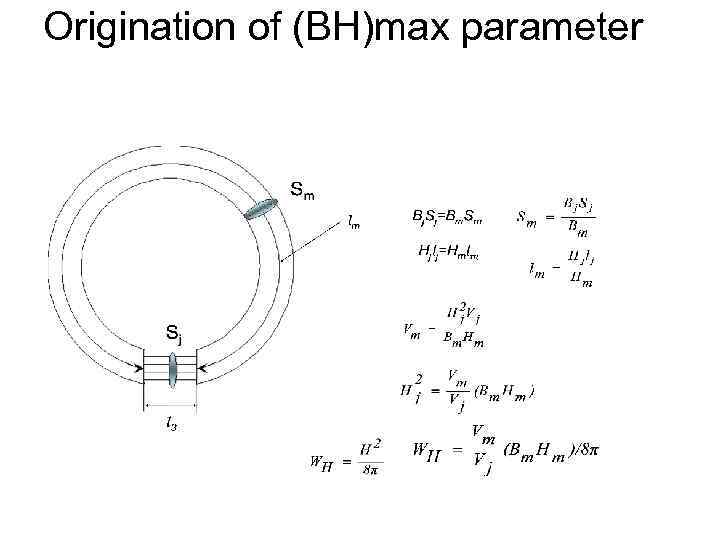 Origination of (BH)max parameter
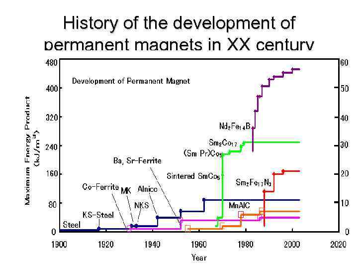 History of the development of permanent magnets in XX century
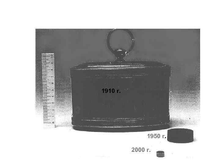 1910 г. 1950 г. 2000 г.
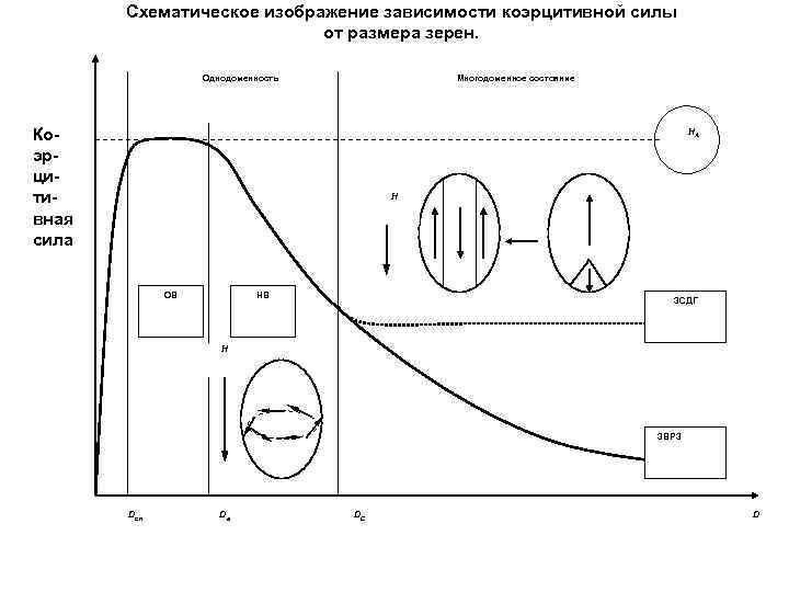 Схематическое изображение зависимости коэрцитивной силы от размера зерен. Однодоменность Многодоменное состояние Коэрцитивная сила НА Н ОВ НВ ЗСДГ Н ЗВРЗ Dсп Dа DС D
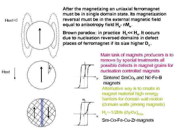 Hext=0 After the magnetizing an uniaxial ferromagnet must be in single domain state. Its magnetization reversal must be in the external magnetic field equal to anisotropy field Ha- n. Ms. Brown paradox: in practice Hc<< Ha. It occurs due to nucleation reversed domains in defect places of ferromagnet if its size higher Dc. Main task of magnets producers is to remove by special treatments all possible defects in magnet grains for nucleation controlled magnets M Hext H M H Sintered Sm. Co 5 and Nd-Fe-B magnets Alternative way is to create in magnet material high energy barriers for domain wall motion (domain walls pinning magnets) Hc=-1/2 Ms (dγ/dx)max Sm-Co-Fe-Cu-Zr-magnets
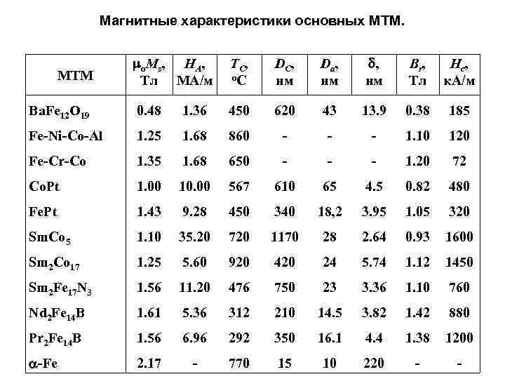 Магнитные характеристики основных МТМ. mo. Ms, HА, Тл МА/м TC, о. С DC, нм Dа , нм d, нм Br, Тл Нс , к. А/м Ba. Fe 12 O 19 0. 48 1. 36 450 620 43 13. 9 0. 38 185 Fe-Ni-Co-Al 1. 25 1. 68 860 - - - 1. 10 120 Fe-Cr-Co 1. 35 1. 68 650 - - - 1. 20 72 Co. Pt 1. 00 10. 00 567 610 65 4. 5 0. 82 480 Fe. Pt 1. 43 9. 28 450 340 18, 2 3. 95 1. 05 320 Sm. Co 5 1. 10 35. 20 720 1170 28 2. 64 0. 93 1600 Sm 2 Co 17 1. 25 5. 60 920 420 24 5. 74 1. 12 1450 Sm 2 Fe 17 N 3 1. 56 11. 20 476 750 23 3. 36 1. 10 760 Nd 2 Fe 14 B 1. 61 5. 36 312 210 14. 5 3. 82 1. 42 880 Pr 2 Fe 14 B 1. 56 6. 96 292 350 16. 1 4. 4 1. 38 1200 a-Fe 2. 17 - 770 15 10 220 - - MTM
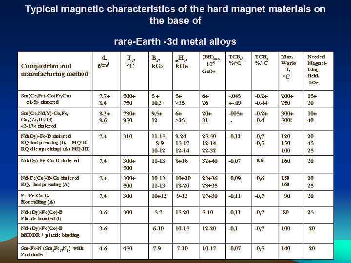 Typical magnetic characteristics of the hard magnet materials on the base of rare-Earth -3 d metal alloys d, Тс , о. С Вr , k. Gs м. Нс, (ВН)мax 106 ТCВu, %/o. C TCHc %/o. C Маx. Work/ Т, Needed Magnetizing field. k. Oe Composition and manufacturing method g/sм 3 Sm(Ce, Pr)-Co(Fe, Cu) « 1 -5» sintered 7, 7 8, 4 500 750 5 10, 3 5 >25 6 26 -. 045 -. 09 -0. 2 -0. 44 200 250 15 20 Sm(Ce, Nd, Y)-Co, Fe, Cu, (Zr, Hf, Ti) « 2 -17» sintered 8, 3 8, 6 780 850 9, 5 12 6 >25 20 31 -005 -. -0. 2 -0. 4 300 500! 10 40 Nd(Dy)-Fe-B sintered RQ hot pressing (I), MQ-II RQ die upsetting) (A) MQ-III 7, 4 310 11 -15 8 -9 10 -12 8 -24 15 -17 12 -14 25 -50 12 -14 22 -32 -0, 12 -0, 7 -0, 5 120 150 100 20 45 25 Nd(Dy)-Fe-Co-B sintered 7, 4 300 500 11 -13 8 18 32 40 -0, 07 -0, 6 160 20 Nd-Fe(Co)-B-Ga sintered RQ, hot pressing (А) 7, 4 300 500 10 -13 11 -13 10 20 18 -20 23 36 28 35 -0, 09 -0, 6 150 160 20 25 Pr-Fe-Cu-B, Hot rolling (А) 7, 4 300 10 12 9 -12 27 30 -0, 11 -0, 7 90 20 Nd-(Dy)-Fe(Co)-B Plastic bonded (I) 3 -6 300 5 -7 15 -20 5 -10 -0, 11 -0, 7 80 25 Nd-(Dy)-Fe(Co)-B h. HDDR + plastic binding 3 -6 6 -10 10 -15 12 -20 -0, 1 -0, 7 100 20 Sm-Fe-N (Sm 2 Fe 17 N 3) with Zn binder 4 -6 7 -9 7 -10 10 -17 -0, 07 -0, 5 140 20 450 k. Oe Gs. Oe о. С
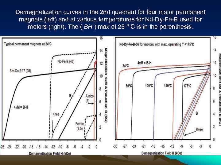 Demagnetization curves in the 2 nd quadrant for four major permanent magnets (left) and at various temperatures for Nd-Dy-Fe-B used for motors (right). The ( BH ) max at 25 ° C is in the parenthesis.
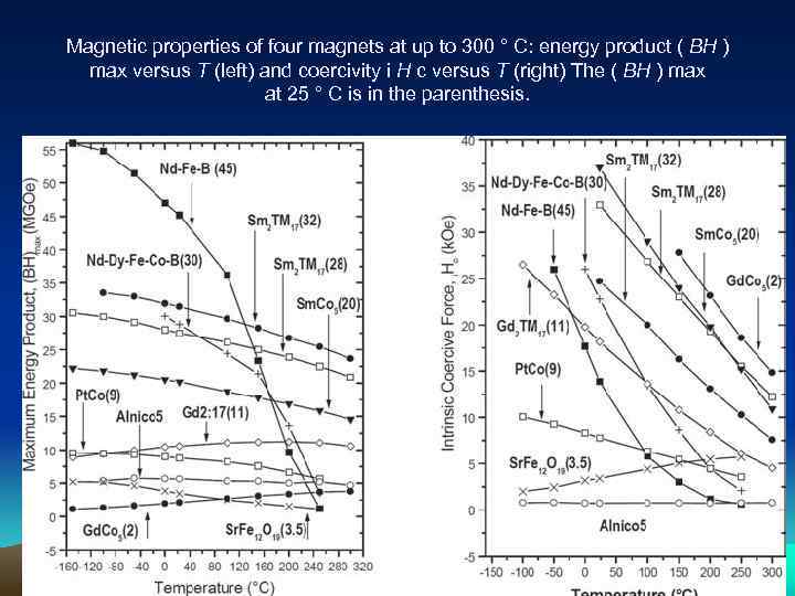 Magnetic properties of four magnets at up to 300 ° C: energy product ( BH ) max versus T (left) and coercivity i H c versus T (right) The ( BH ) max at 25 ° C is in the parenthesis.
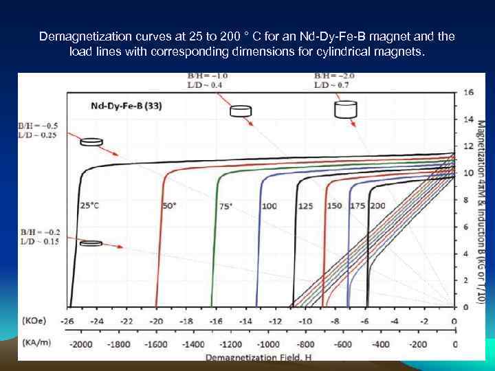 Demagnetization curves at 25 to 200 ° C for an Nd-Dy-Fe-B magnet and the load lines with corresponding dimensions for cylindrical magnets.
![Output of Nd. Fe. B permanent magnets during the past ten years (left) [22] Output of Nd. Fe. B permanent magnets during the past ten years (left) [22]](https://present5.com/presentation/3/58786945_300529124.pdf-img/58786945_300529124.pdf-13.jpg) Output of Nd. Fe. B permanent magnets during the past ten years (left) [22] and predicted percentage sales ($) for 2010 of the major permanent magnets in the world (right).
Output of Nd. Fe. B permanent magnets during the past ten years (left) [22] and predicted percentage sales ($) for 2010 of the major permanent magnets in the world (right).
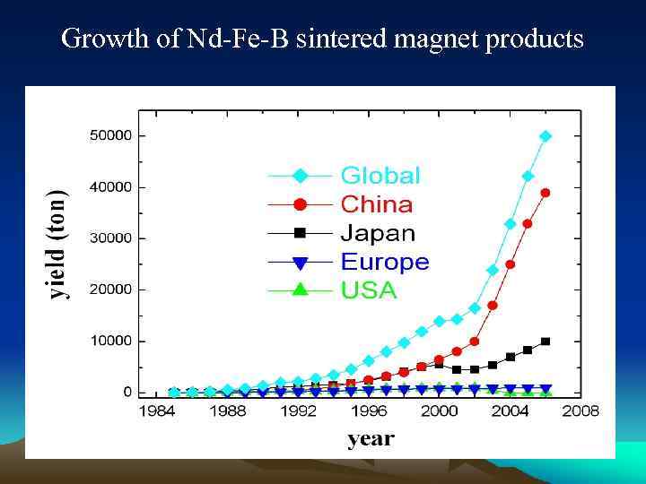 Growth of Nd-Fe-B sintered magnet products
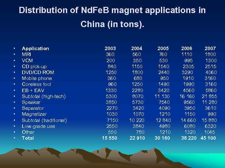 Distribution of Nd. Fe. B magnet applications in China (in tons). • • • • Application MRI VCM CD pick-up DVD/CD ROM Mobile phone Coreless tool EB + EAV Subtotal (high-tech) Speaker Separator Magnetizer Subtotal (traditional) Low-grade use Other Total 2003 360 200 840 1250 360 960 1330 5300 3850 2270 1030 7150 2550 15 550 2004 560 350 1150 1800 680 1250 2280 8070 5730 3420 1070 10 220 3840 780 22 910 2005 760 530 1540 2440 950 1490 3420 11 130 7540 4090 1210 12 840 4980 1210 30 160 2006 2007 1110 1800 995 1300 2305 2515 3290 4060 1910 3160 1990 3160 4560 5860 16 160 21 855 9560 11 280 3950 3610 1150 990 14 660 15 880 6080 6320 1045 38 220 45 100
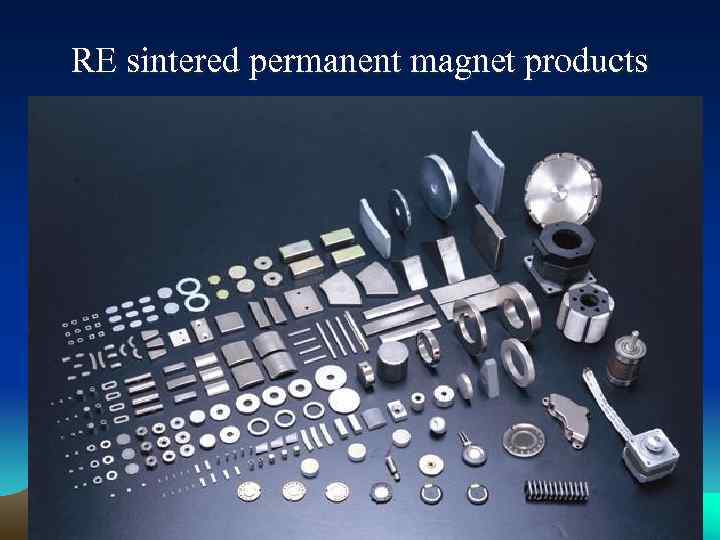 RE sintered permanent magnet products
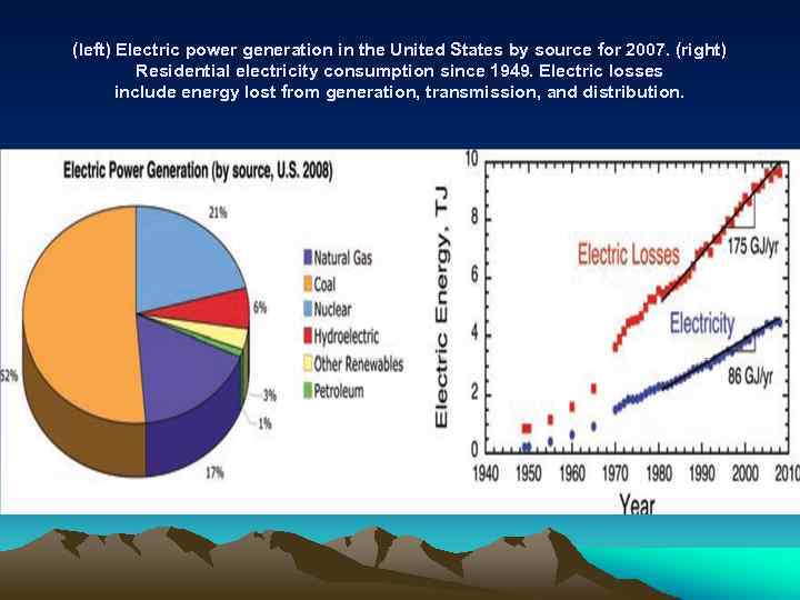 (left) Electric power generation in the United States by source for 2007. (right) Residential electricity consumption since 1949. Electric losses include energy lost from generation, transmission, and distribution.
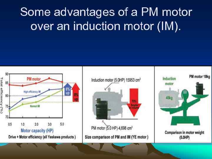 Some advantages of a PM motor over an induction motor (IM).
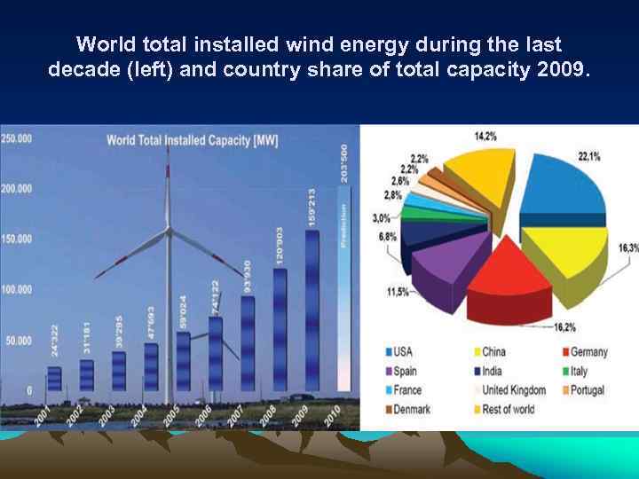 World total installed wind energy during the last decade (left) and country share of total capacity 2009.
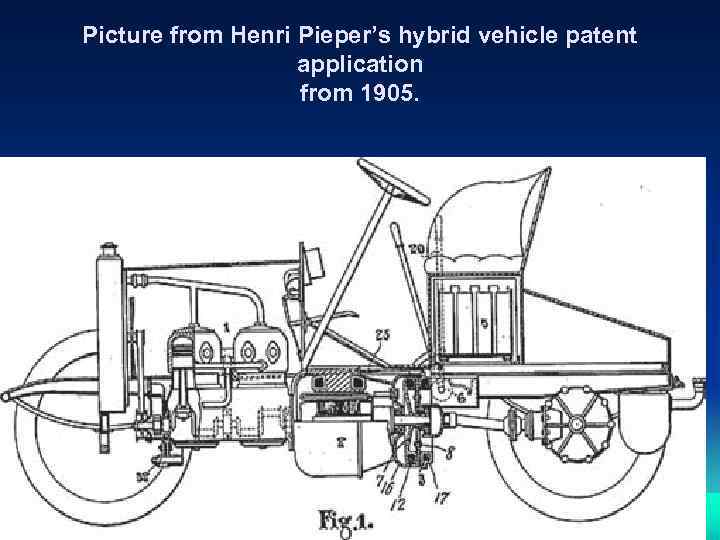 Picture from Henri Pieper’s hybrid vehicle patent application from 1905.
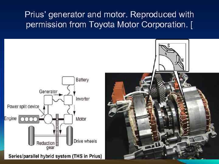 Prius’ generator and motor. Reproduced with permission from Toyota Motor Corporation. [
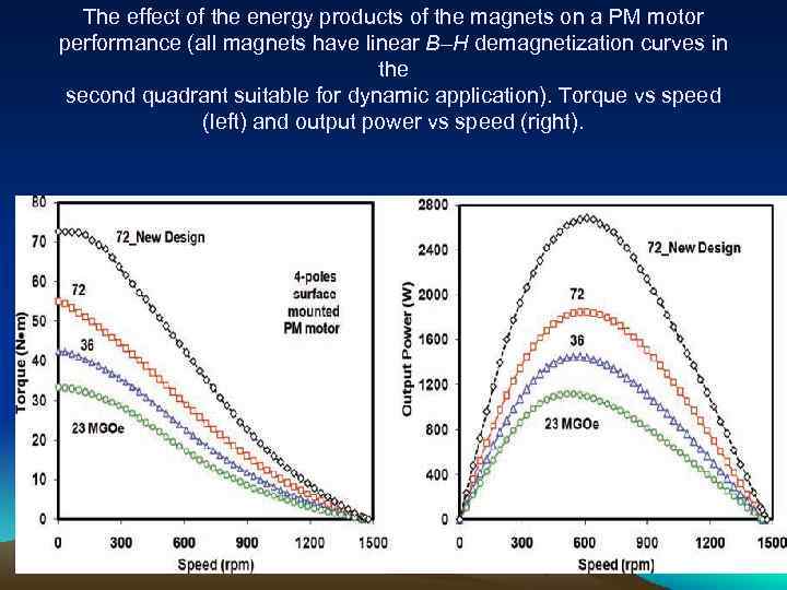 The effect of the energy products of the magnets on a PM motor performance (all magnets have linear B–H demagnetization curves in the second quadrant suitable for dynamic application). Torque vs speed (left) and output power vs speed (right).
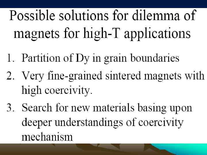
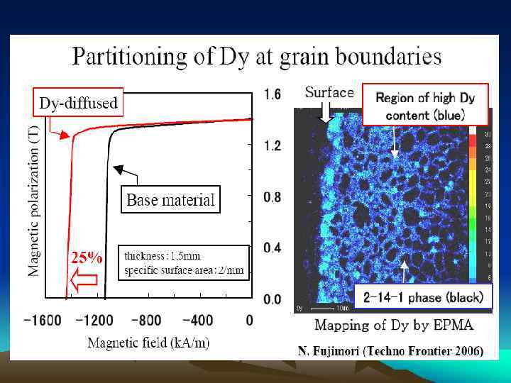
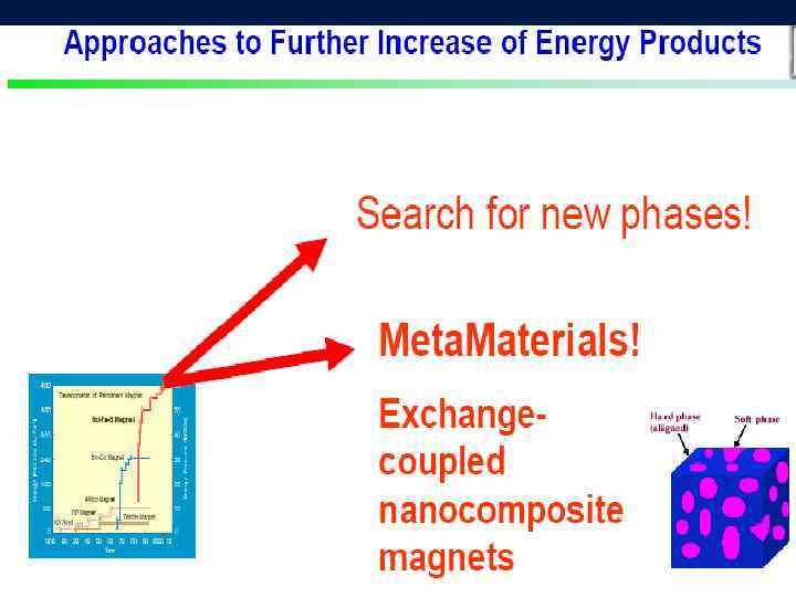
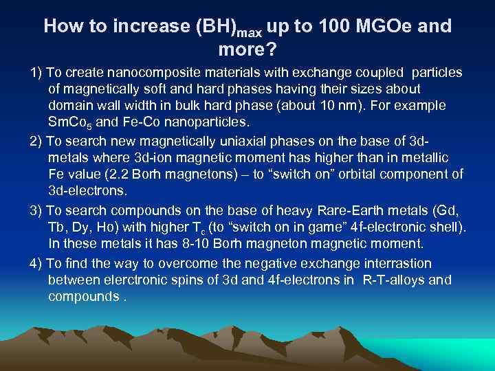 How to increase (BH)max up to 100 MGOe and more? 1) To create nanocomposite materials with exchange coupled particles of magnetically soft and hard phases having their sizes about domain wall width in bulk hard phase (about 10 nm). For example Sm. Co 5 and Fe-Co nanoparticles. 2) To search new magnetically uniaxial phases on the base of 3 dmetals where 3 d-ion magnetic moment has higher than in metallic Fe value (2. 2 Borh magnetons) – to “switch on” orbital component of 3 d-electrons. 3) To search compounds on the base of heavy Rare-Earth metals (Gd, Tb, Dy, Ho) with higher Tc (to “switch on in game” 4 f-electronic shell). In these metals it has 8 -10 Borh magneton magnetic moment. 4) To find the way to overcome the negative exchange interrastion between elerctronic spins of 3 d and 4 f-electrons in R-T-alloys and compounds.
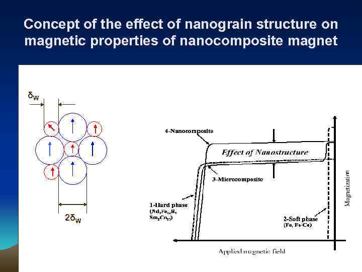 Concept of the effect of nanograin structure on magnetic properties of nanocomposite magnet δW 2δW
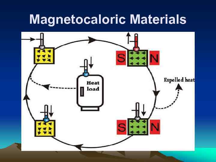 Magnetocaloric Materials
![Comparison of different potential magnetocaloric materials. Gd is included as reference material ( [d] Comparison of different potential magnetocaloric materials. Gd is included as reference material ( [d]](https://present5.com/presentation/3/58786945_300529124.pdf-img/58786945_300529124.pdf-30.jpg) Comparison of different potential magnetocaloric materials. Gd is included as reference material ( [d] means direct measurement, [c] is calculated from a combination of measurements). The costs may strongly fluctuate due to market demands and quality of starting materials. Reproduced . Material Density T range (K) Δ S max (2 T) (J kg) Δ T (2 T) (K) T C (K) Cost ∋ /kg Gd 270– 310 5 5. 8 [d] 293 20 7. 9 Gd 5 Ge 2 Si 2 150– 290 27 6. 6 [d] 272 60 7. 5 La(Fe, Si)H 180– 350 19 7 [c] 300 8 7. 1 Mn. As 220– 320 32 4. 1 [d] 287 10 6. 8 Mn. Ni. Ga 310– 350 15 2 [c] 317 10 8. 2 Mn. Fe(P, As) 150– 450 32 6 [d] 292 7 7. 4
Comparison of different potential magnetocaloric materials. Gd is included as reference material ( [d] means direct measurement, [c] is calculated from a combination of measurements). The costs may strongly fluctuate due to market demands and quality of starting materials. Reproduced . Material Density T range (K) Δ S max (2 T) (J kg) Δ T (2 T) (K) T C (K) Cost ∋ /kg Gd 270– 310 5 5. 8 [d] 293 20 7. 9 Gd 5 Ge 2 Si 2 150– 290 27 6. 6 [d] 272 60 7. 5 La(Fe, Si)H 180– 350 19 7 [c] 300 8 7. 1 Mn. As 220– 320 32 4. 1 [d] 287 10 6. 8 Mn. Ni. Ga 310– 350 15 2 [c] 317 10 8. 2 Mn. Fe(P, As) 150– 450 32 6 [d] 292 7 7. 4
 • БЛАГОДАРЮ ЗА ВНИМАНИЕ


