58ecd45067d0ffebdd3776508232e7e0.ppt
- Количество слайдов: 60
 RS 232 AND RS 485 – unit 3
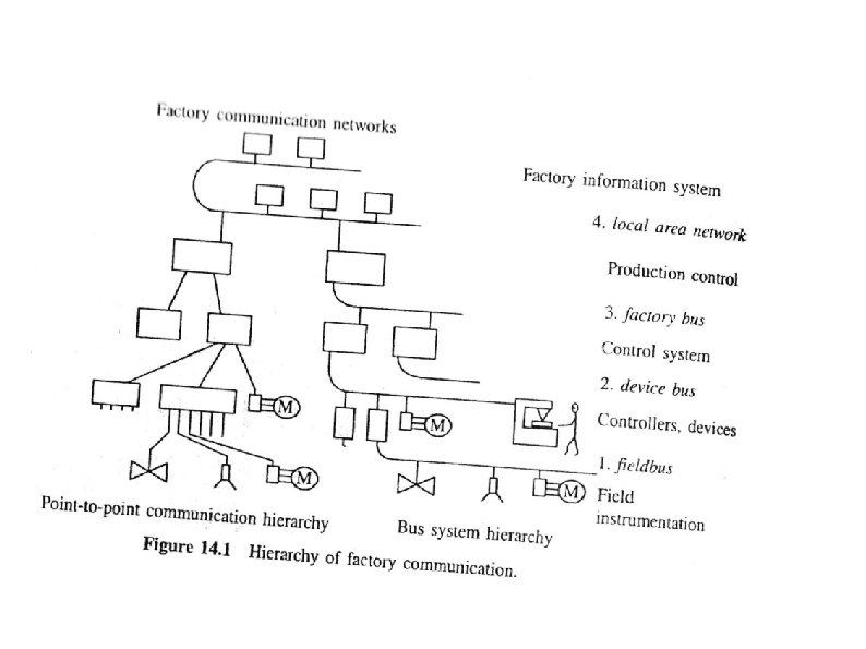
 Modern instrumentation and control systems Mechanical-short distance Pneumatic- larger distance, larger pipes, logical control signals Individual lines for individual devices, pneumatic grouped Electrical- long distance, wires Analog Digital Electronics, Programmable devices Computers Many devices forming networks having standard protocols
 OSI Model OSI MODEL
 OSI Model Communication Architecture Strategy for connecting host computers and other communicating equipment. Defines necessary elements for data communication between devices. A communication architecture, therefore, defines a standard for the communicating hosts. A programmer formats data in a manner defined by the communication architecture and passes it on to the communication software. Separating communication functions adds flexibility, for example, we do not need to modify the entire host software to include more communication devices.
 OSI Model Layer Architecture Layer architecture simplifies the network design. It is easy to debug network applications in a layered architecture network. The network management is easier due to the layered architecture. Network layers follow a set of rules, called protocol. The protocol defines the format of the data being exchanged, and the control and timing for the handshake between layers.
 Model International standard organization (ISO) established a committee") OSI Model Open Systems Interconnection (OSI) Model International standard organization (ISO) established a committee in 1977 to develop an architecture for computer communication. Open Systems Interconnection (OSI) reference model is the result of this effort. In 1984, the Open Systems Interconnection (OSI) reference model was approved as an international standard for communications architecture. Term “open” denotes the ability to connect any two systems which conform to the reference model and associated standards.
OSI Model Open Systems Interconnection (OSI) Model International standard organization (ISO) established a committee in 1977 to develop an architecture for computer communication. Open Systems Interconnection (OSI) reference model is the result of this effort. In 1984, the Open Systems Interconnection (OSI) reference model was approved as an international standard for communications architecture. Term “open” denotes the ability to connect any two systems which conform to the reference model and associated standards.
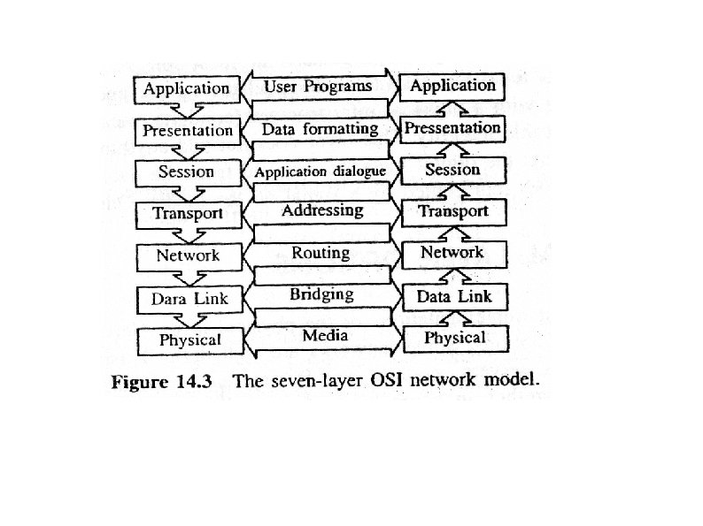
 OSI Model OSI Reference Model The OSI model is now considered the primary Architectural model for inter-computer communications. The OSI model describes how information or data makes its way from application programmes (such as spreadsheets) through a network medium (such as wire) to another application programme located on another network. The OSI reference model divides the problem of moving information between computers over a network medium into SEVEN smaller and more manageable problems. This separation into smaller more manageable functions is known as layering.
 OSI Model OSI Reference Model: 7 Layers
 OSI Model OSI: A Layered Network Model The process of breaking up the functions or tasks of networking into layers reduces complexity. Each layer provides a service to the layer above it in the protocol specification. Each layer communicates with the same layer’s software or hardware on other computers. The lower 4 layers (transport, network, data link and physical —Layers 4, 3, 2, and 1) are concerned with the flow of data from end to end through the network. The upper four layers of the OSI model (application, presentation and session—Layers 7, 6 and 5) are orientated more toward services to the applications. Data is Encapsulated with the necessary protocol information as it moves down the layers before network transit.
 OSI Model Physical Layer Provides physical interface for transmission of information. Defines rules by which bits are passed from one system to another on a physical communication medium. Covers all - mechanical, electrical, functional and procedural - aspects for physical communication. Such characteristics as voltage levels, timing of voltage changes, physical data rates, maximum transmission distances, physical connectors, and other similar attributes are defined by physical layer specifications.
 OSI Model Data Link Layer Data link layer attempts to provide reliable communication over the physical layer interface. Breaks the outgoing data into frames and reassemble the received frames. Create and detect frame boundaries. Handle errors by implementing an acknowledgement and retransmission scheme. Implement flow control. Supports points-to-point as well as broadcast communication. Supports simplex, half-duplex or full-duplex communication.
 through the network. Defines the most optimum") Network Layer Implements routing of frames (packets) through the network. Defines the most optimum path the packet should take from the source to the destination Defines logical addressing so that any endpoint can be identified. Handles congestion in the network. Facilitates interconnection between heterogeneous networks (Internetworking). The network layer also defines how to fragment a packet into smaller packets to accommodate different media.
Network Layer Implements routing of frames (packets) through the network. Defines the most optimum path the packet should take from the source to the destination Defines logical addressing so that any endpoint can be identified. Handles congestion in the network. Facilitates interconnection between heterogeneous networks (Internetworking). The network layer also defines how to fragment a packet into smaller packets to accommodate different media.
 OSI Model Transport Layer Purpose of this layer is to provide a reliable mechanism for the exchange of data between two processes in different computers. Ensures that the data units are delivered error free. Ensures that data units are delivered in sequence. Ensures that there is no loss or duplication of data units. Provides connectionless or connection oriented service. Provides for the connection management. Multiplex multiple connection over a single channel.
 OSI Model Session Layer Session layer provides mechanism for controlling the dialogue between the two end systems. It defines how to start, control and end conversations (called sessions) between applications. This layer requests for a logical connection to be established on an end-user’s request. Any necessary log-on or password validation is also handled by this layer. Session layer is also responsible for terminating the connection. This layer provides services like dialogue discipline which can be full duplex or half duplex. Session layer can also provide check-pointing mechanism such that if a failure of some sort occurs between checkpoints, all data can be retransmitted from the last checkpoint.
 OSI Model Presentation Layer Presentation layer defines the format in which the data is to be exchanged between the two communicating entities. Also handles data compression and data encryption (cryptography).
 OSI Model Application Layer Application layer interacts with application programs and is the highest level of OSI model. Application layer contains management functions to support distributed applications. Examples of application layer are applications such as file transfer, electronic mail, remote login etc.
 OSI Model OSI in Action A message begins at the top application layer and moves down the OSI layers to the bottom physical layer. As the message descends, each successive OSI model layer adds a header to it. A header is layer-specific information that basically explains what functions the layer carried out. Conversely, at the receiving end, headers are striped from the message as it travels up the corresponding layers.
 TCP/IP Model TCP/IP MODEL
 TCP/IP Model OSI & TCP/IP Models
 Management of") TCP/IP Model Application Layer Application programs using the network Transport Layer (TCP/UDP) Management of end-to-end message transmission, error detection and error correction Network Layer (IP) Handling of datagrams : routing and congestion Data Link Layer Management of cost effective and reliable data delivery, access to physical networks Physical Layer Physical Media
TCP/IP Model Application Layer Application programs using the network Transport Layer (TCP/UDP) Management of end-to-end message transmission, error detection and error correction Network Layer (IP) Handling of datagrams : routing and congestion Data Link Layer Management of cost effective and reliable data delivery, access to physical networks Physical Layer Physical Media
 RS 232
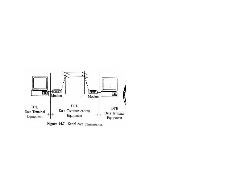
 Electronics Industry Association EIA RS 232 called as “interface between DTE and DCE Employing Serial Binary Data Interchange” The RS 232 standard underwent several revisions, the C issue known as RS 232 C was issued in 1969 further revisions and in 1986 Revision D was released Further updates and revisions have occurred since then and the current version is TIA-232 -F issued in 1997 under the title: "Interface Between Data Terminal Equipment and Data Circuit. Terminating Equipment Employing Serial Binary Data Interchange. " Telecommunications Industry Alliance (TIA).
 RS-232 key features Single-Ended Point-to-Point Interface Large Polar Driver Output Swing Controlled Driver Slew Rate Fully Defined Interface 20 kbps Maximum Data Rate 25 pin D-SUB male connector at the DTE (Computer) 25 pin D-SUB female connector at the DCE (Modem)
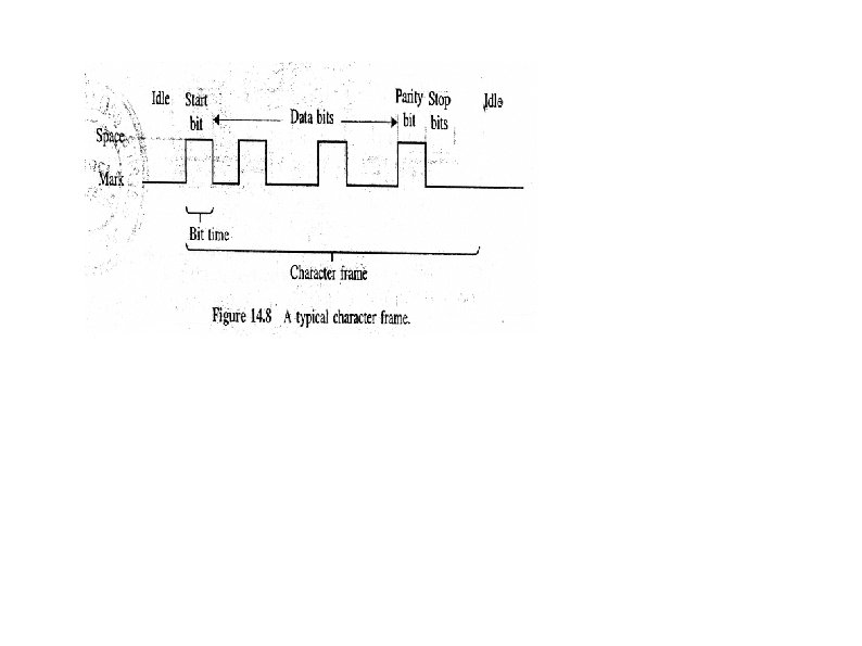
 The RS-232 standard provided an ideal method of linking many other remote items to computers and data recorders. As a result, RS-232 became an industry standard RS-232 connections RS 232 C: common type found is the 25 pin D-type connector. RS 232 signal levels For RS 232 data signals voltage of between -3 V and -25 V represents a logic 1. The logic 0 is represented by a voltage of between +3 V and +25 V. data is sent serially on RS 232 using ASCII RS 232 data transmission is normally asynchronous Once the start bit is sent the receiver will sample the centre of each bit to see the level
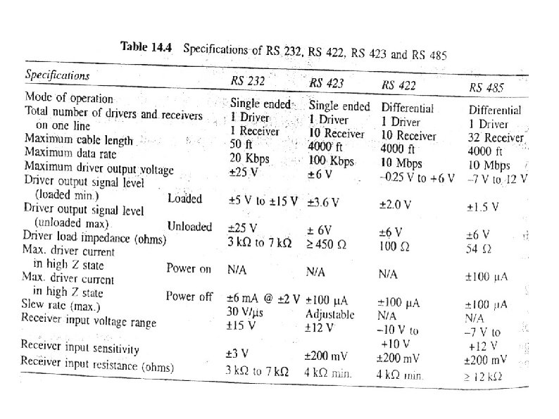
 RS-232 specifications
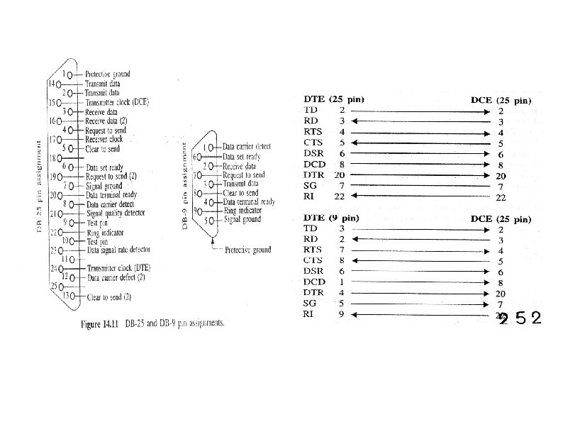
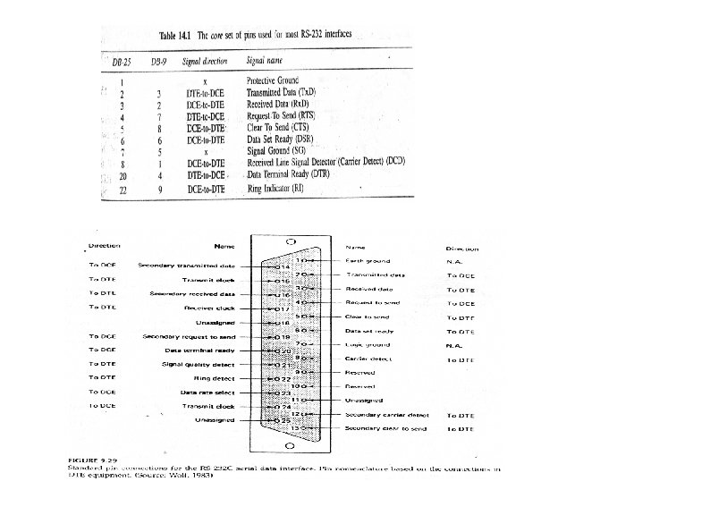
 Lines and their usage: Four types. They are Data, Control, Timing and Ground. Not all of them are required all the time. the control circuits is Data Carrier Detected (DCD). This shows when the modem has detected a carrier on the telephone line and a connection appears to have been made. It produces a high, which is maintained until the connection is lost. Data Terminal Ready (DTR) and Data Set Ready (DSR) When the terminal is ready to start handling data it flags this on the DTR line. modem is also ready then it returns its signal on the DSR line
 and Clear To Send (CTS) This pair of circuits are") Request To Send (RTS) and Clear To Send (CTS) This pair of circuits are used together. The terminal equipment will flag that it has data to send. The modem will then return the CTS signal to give the all clear after a short delay. Grounding: 1. protective ground ensures that both equipments are at the same earth potential. This is very useful when there is a possibility that either equipment is not earthed. 2. The signal ground is used as the return for the digital signals travelling along the data link.
Request To Send (RTS) and Clear To Send (CTS) This pair of circuits are used together. The terminal equipment will flag that it has data to send. The modem will then return the CTS signal to give the all clear after a short delay. Grounding: 1. protective ground ensures that both equipments are at the same earth potential. This is very useful when there is a possibility that either equipment is not earthed. 2. The signal ground is used as the return for the digital signals travelling along the data link.
 Transmission method Method 1: X-ON / X-OFF X-ON is received at the transmitting end, data transmission is started Once the input buffer on the terminal or printer starts to become full the X-OFF character is sent to stop the data. Method 2: EXT/ACK. Using this method the data is separated into blocks and after each block has been sent the control code ETX is transmitted to show the end of this block of text. Once the data accepted and sufficient space in the input buffer the ACK or acknowledgement control code is sent. Once this has been received, the next block of data is sent.
 SOH Start of header STX") Control Codes Names Code Name Function NUL Null (blank) SOH Start of header STX Start of text ETX End of text EOT End of transmission ENQ Enquiry ACK Acknowledgement BEL Bell (Audible) BS Backspace HT Horizontal tab LF Line feed VT Vertical tab FF Form feed CR Carriage return SO Shift out SI Shift in DLE Data link escape DC 1 Device control 1 DC 2 Device control 2 DC 3 Device control 3 DC 4 Device control 4 NAK Negative acknowledgement SYN Synchronous idle ETB End of transmission block CAN Cancel EM End of medium SUB Substitute ESC Escape FS File separator GS Group separator RS Record separator US Unit separator DEL Delete
Control Codes Names Code Name Function NUL Null (blank) SOH Start of header STX Start of text ETX End of text EOT End of transmission ENQ Enquiry ACK Acknowledgement BEL Bell (Audible) BS Backspace HT Horizontal tab LF Line feed VT Vertical tab FF Form feed CR Carriage return SO Shift out SI Shift in DLE Data link escape DC 1 Device control 1 DC 2 Device control 2 DC 3 Device control 3 DC 4 Device control 4 NAK Negative acknowledgement SYN Synchronous idle ETB End of transmission block CAN Cancel EM End of medium SUB Substitute ESC Escape FS File separator GS Group separator RS Record separator US Unit separator DEL Delete
 RS 485
 RS 485 “Standard for electrical characteristics of generators and receivers for use in Balanced Digital Multipoint Systems'
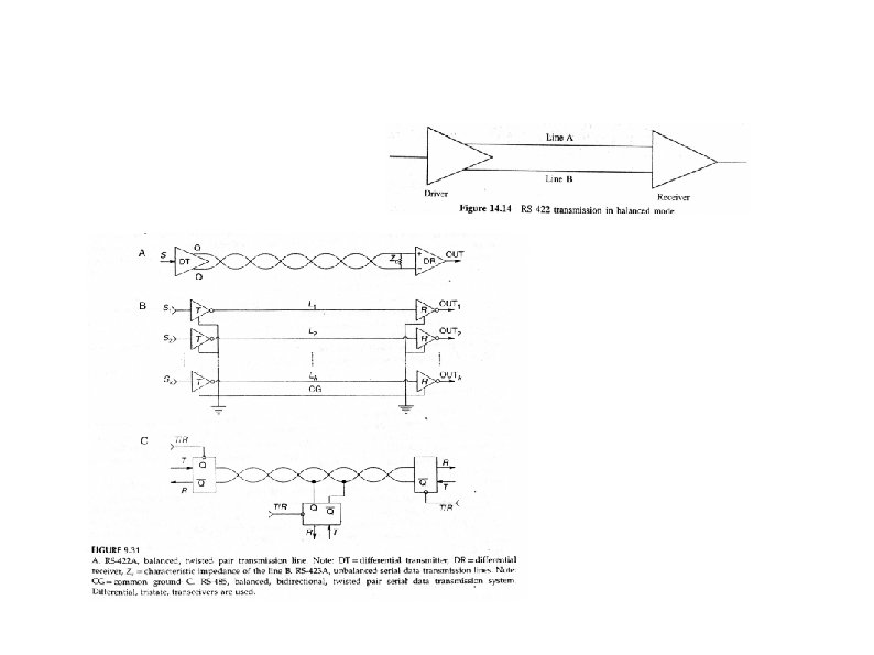
 EIA-485, also known as TIA/EIA-485 or RS-485, is a standard defining the electrical characteristics of drivers and receivers for use in balanced digital multipoint systems. The standard is published by the ANSI Telecommunications Industry Association/Electronic Industries Alliance (TIA/EIA). Digital communications networks implementing the EIA-485 standard can be used effectively over long distances and in electrically noisy environments. Multiple receivers may be connected to such a network in a linear, multi-drop configuration. These characteristics make such networks useful in industrial environments and similar applications.
 EIA-485 only specifies electrical characteristics of the driver and the receiver. It does not specify or recommend any communications protocol. EIA-485 enables the configuration of inexpensive local networks and multidrop communications links. It offers high data transmission speeds (35 Mbit/s up to 10 m and 100 kbit/s at 1200 m). Since it uses a differential balanced line over twisted pair (like EIA 422), it can span relatively large distances (up to 4000 feet or just over 1200 meters). A rule of thumb is that the speed in bit/s multiplied by the length in meters should not exceed 108. Thus a 50 meter cable should not signal faster than 2 Mbit/s. [1] In contrast to EIA-422, which has a single driver circuit which cannot be switched off, EIA-485 drivers need to be put in transmit mode explicitly by asserting a signal to the driver. This allows EIA-485 to implement linear topologies using only two wires. The equipment located along a set of EIA-485 wires are interchangeably called nodes, stations and devices.
 • The recommended arrangement of the wires is as a connected series of point-to-point (multidropped) nodes, a line or bus, not a star, ring, or multiply-connected network. Ideally, the two ends of the cable will have a termination resistor connected across the two wires. • Without termination resistors, reflections of fast driver edges can cause multiple data edges that can cause data corruption. Termination resistors also reduce electrical noise sensitivity due to the lower impedance, and bias resistors (see below) are required. The value of each termination resistor should be equal to the cable impedance (typically, 120 ohms for twisted pairs). • Star and ring topologies are not recommended because of signal reflections or excessively low or high termination impedance. • Somewhere along the set of wires, pull up or pull down resistors are established to Fail -safe bias each data line/wire when the lines are not being driven by any device. • This way, the lines will be biased to known voltages and nodes will not interpret the noise from undriven lines as actual data; without biasing resistors, the data lines float in such a way that electrical noise sensitivity is greatest when all device stations are silent or unpowered
 Master-slave arrangement Often in a master-slave arrangement when one device dubbed "the master" initiates all communication activity, the master device itself provides the bias and not the slave devices. In this configuration, the master device is typically centrally located along the set of EIA-485 wires, so it would be two slave devices located at the physical end of the wires that would provide the termination. The master device itself would provide termination if it were located at a physical end of the wires, but that is often a bad design[4] as the master would be better located at a halfway point between the slave devices. Note that it is not a good idea to apply the bias at multiple node locations, because, by doing so, the effective bias resistance is lowered, which could possibly cause a violation of the EIA-485 specification and cause communications to malfunction. By keeping the biasing with the master, slave device design is simplified and this situation is avoided.
 Three-wire connection RS-485 3 wire connection Even though the data is transmitted over a 2 -wire twisted pair bus, all EIA-485 transceivers interpret the voltage levels of the differential signals with respect to a third common voltage. Without this common reference, a set of transceivers may interpret the differential signals incorrectly. In a typical setup, this third voltage is implied in the power supply common/ground connection. However, fundamentally speaking, there is nothing requiring this common voltage to be the same as the power supply. In fact, certain MS/TP (Master Slave / Token Passing) wiring requires full isolation between the various EIA-485 devices and have to run the third wire for the common connection
 Full duplex operation EIA-485, like EIA-422 can be made full-duplex by using four wires. Since EIA-485 is a multi-point specification, however, this is not necessary in many cases. EIA-485 and EIA-422 can interoperate with certain restrictions. Converters between EIA-485 and other formats are available to allow a personal computer to communicate with remote devices. By using "Repeaters" and "Multi-Repeaters" very large RS-485 networks can be formed. The Application Guidelines for TIA/EIA-485 -A has one diagram called "Star Configuration. Not recommended. " Using an RS-485 "Multi-Repeater" can allow for "Star Configurations" with "Home Runs" (or multi-drop) connections similar to Ethernet Hub/Star implementations (with greater distances). Hub/Star systems (with "Multi-Repeaters") allow for very maintainable systems, without violating any of the RS-485 specifications. Repeaters can also be used to extend the distance or number of nodes on a network.
 Applications EIA-485 signals are used in a wide range of computer and automation systems. In a computer system, SCSI-2 and SCSI-3 may use this specification to implement the physical layer for data transmission between a controller and a disk drive. EIA-485 is used for low-speed data communications in commercial aircraft cabins vehicle bus. It requires minimal wiring, and can share the wiring among several seats, reducing weight. EIA-485 is used as the physical layer underlying many standard and proprietary automation protocols used to implement Industrial Control Systems, including the most common versions of Modbus and Profibus. These are used in programmable logic controllers and on factory floors. Since it is differential, it resists electromagnetic interference from motors and welding equipment. In theatre and performance venues EIA-485 networks are used to control lighting and other systems using the DMX 512 protocol. EIA-485 is also used in building automation as the simple bus wiring and long cable length is ideal for joining remote devices. It may be used to control video surveillance systems or to interconnect security control panels and devices such as access control card readers. Although many applications use EIA-485 signal levels, the speed, format, and protocol of the data transmission is not specified by EIA-485. Interoperation even of similar devices from different manufacturers is not assured by compliance with the signal levels alone.
 Connectors • EIA-485 does not specify any connector or pinout. Circuits may be terminated on screw terminals, D-subminiature connectors, or other types of connectors. Signs of common mistakes • From a software engineer's perspective, miswired RS-485 can lead to spurious characters because a spurious mark bit is seen. A bus without good pull up and pull down resistors will be noise-sensitive. These can be system-wide (albeit trivial) problems that require looking beyond just the CPU that is being programmed. Pin labeling • The EIA-485 differential line consists of two pins: • • A aka '−' aka Tx. D-/Rx. D- aka inverting pin • • B aka '+' aka Tx. D+/Rx. D+ aka non-inverting pin • • SC aka G aka reference pin
 Waveform example The graph below shows potentials of the '+' and '−' pins of an EIA-485 line during transmission of one byte (0 x. D 3, least significant bit first) of data using an asynchronous start-stop method. A (U+)is greater than B(U-) - logic 1 A (U+)is less than B - logic 0
 RS-422 is a common short form and former official title of American National Standards Institute (ANSI) standard ANSI/TIA/EIA-422 -B and its international equivalent ITU-T Recommendation T -REC-V. 11, [1] also known as X. 27. These technical standards specify the electrical characteristics of the balanced voltage digital interface circuit. RS-422 provides for data transmission, using balanced or differential signaling, with unidirectional/non-reversible, terminated or non-terminated transmission lines, point to point, or multi-drop. In contrast to EIA-485 (which is multi-point instead of multi-drop), EIA-422/V. 11 does not allow multiple drivers but only multiple receivers. Several key advantages offered by this standard include the differential receiver, a differential driver and data rates as high as 10 megabaud at 12 metres (40 ft). EIA-422 only specifies the electrical signaling characteristics of a single balanced signal. Protocols and pin assignments are defined in other specifications. The mechanical connections for this interface are specified by EIA-530 (DB-25 connector) or EIA -449 (DC-37 connector), however devices exist which have 4 screw-posts to implement the transmit and receive pair only. The maximum cable length is 1200 m. Maximum data rates are 10 Mbit/s at 12 m or 100 kbit/s at 1200 m. EIA-422 cannot implement a truly multi-point communications network (such as with EIA-485), however one driver can be connected to up to ten receivers.
 RS 422 - “Electrical Characteristics of balanced Voltage Digital Interface Circuits” Va~Vb=0. 4 to 12 V Logic 0= > Vb + then Va Logic 1= > Va + then Vb
 A common use of EIA-422 is for RS-232 extenders In video editing studios it is used to link control signals for all video and audio players/recorders to a central control board. Also, an RS-232 -compatible variant of RS-422 using a mini-DIN-8 connector was widely used on Macintosh hardware until it was replaced by Intel's Universal Serial Bus on the i. Mac in 1998. EIA-422 can interoperate with interfaces designed to MIL-STD-188 -114 B, but they are not identical. EIA-422 uses a nominal 0 to 5 volt signal while MIL-STD-188 -114 B uses a signal symmetric about 0 V. However the tolerance for common mode voltage in both specifications allows them to interoperate. Care must be taken with the termination network. EIA-423 is a similar specification for unbalanced signaling. When used in relation to communications wiring, RS-422 wiring refers to cable made of 2 sets of twisted pair, often with each pair being shielded, and a ground wire. While a double pair cable may be practical for many RS-422 applications, the RS-422 specification only defines one signal path and does not assign any function to it. Any complete cable assembly (i. e. with connectors) should be labeled with the specification that defined the signal function and mechanical layout of the connector, such as RS-449.
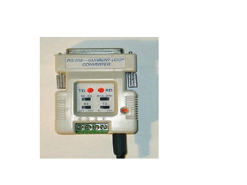
 CURRENT LOOP a current loop is a communication interface that uses current instead of voltage for signaling. Current loops can be used over moderately long distances (tens of kilometres) can be interfaced with optically isolated links. Analog current loops are used where a device must be monitored or controlled remotely over a pair of conductors. Only one current level can be present at any time
 The key advantages of the current loop Accuracy of the signal is not affected by voltage drop in the interconnecting wiring, and that the loop can supply operating power to the device. Even if there is significant electrical resistance in the line, the current loop transmitter will maintain the proper current, up to its maximum voltage capability
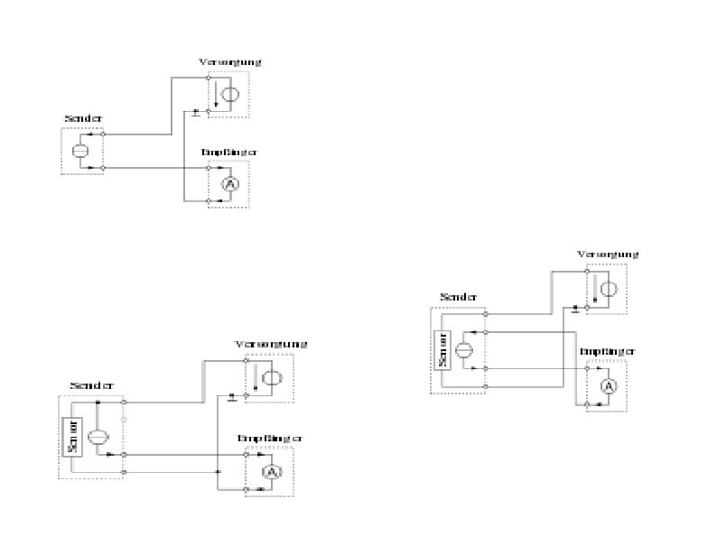
 Depending on the source of current for the loop, devices may be classified as active (supplying power) passive (relying on loop power)