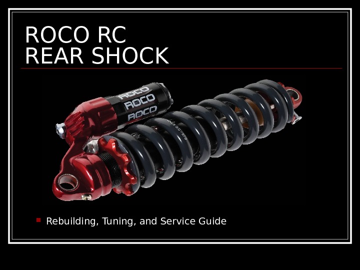
ROCO RC REAR SHOCK Rebuilding, Tuning, and

- Размер: 20.1 Mегабайта
- Количество слайдов: 37
Описание презентации ROCO RC REAR SHOCK Rebuilding, Tuning, and по слайдам
 ROCO RC REAR SHOCK Rebuilding, Tuning, and Service Guide
 Warning! Содержание под высоким давлением! Освободить всех воздухом и соблюдайте осторожность перед открытием шок. Невозможность удаления воздуха может привести к большой беспорядок, серьезным травмам или смерти. Надевайте защитные очки и защитные перчатки во время этих операций. Когда шок был удален из прокат, будьте осторожны, чтобы не » раздувать » или сжать прокат связь дальше, чем он предназначен. Некоторые каркасных конструкций позволит этого, другие нет. Убедитесь, что все отходы нефтепродуктов утилизируются должным образом. Вначале земля!
 The concept of ROCO RC Reliability Compatibility Complete serviceability Quick set-up External adjustments; preload, rebound, and mid/high speed compression. Internal adjustments; air volume, low/mid range comp. Less down time for overhauls. Unlimited tuning*. Step by step guide that will lead you through the process and get you back on the trail in no time! * Changing the shim stacks are only recommended for suspension professionals and Marzocchi Factor Service centers*. Please contact a service center near you. Warning — Basic mechanical aptitude may still not be enough to service your shock.
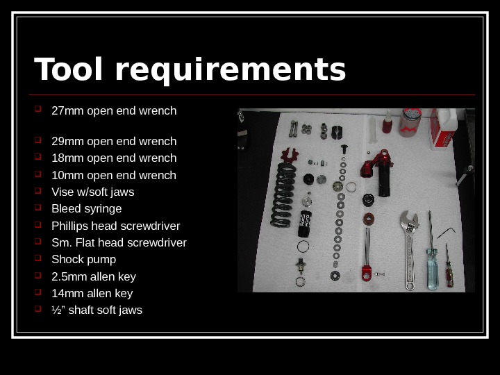
 Tool requirements 27 mm open end wrench 29 mm open end wrench 18 mm open end wrench 10 mm open end wrench Vise w/soft jaws Bleed syringe Phillips head screwdriver Sm. Flat head screwdriver Shock pump 2. 5 mm allen key 14 mm allen key ½” shaft soft jaws
 Oil requirements Fully synthetic 5 wt shock oil. Oil specifications — oil bottles here
 Clean work area Очистить и удалить пыль и мусор из вашей рабочей зоны до обслуживание ваш удар. Это поможет гарантировать качество.
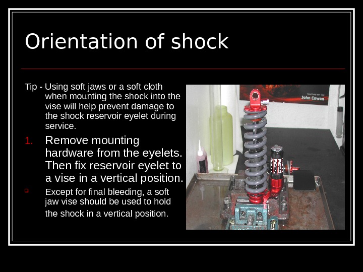
 Orientation of shock Tip — Using soft jaws or a soft cloth when mounting the shock into the vise will help prevent damage to the shock reservoir eyelet during service. 1. Remove mounting hardware from the eyelets. Then fix reservoir eyelet to a vise in a vertical position. Except for final bleeding, a soft jaw vise should be used to hold the shock in a vertical position.
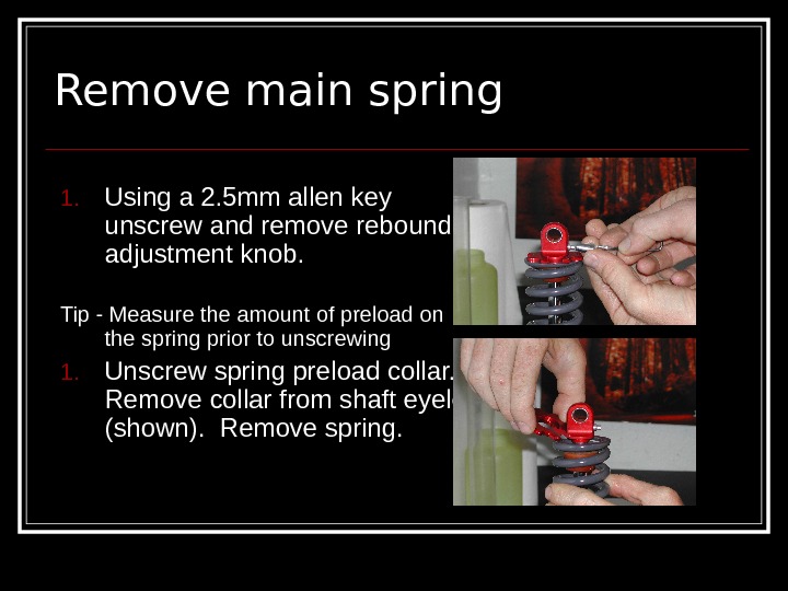
 Remove main spring 1. Using a 2. 5 mm allen key unscrew and remove rebound adjustment knob. Tip — Measure the amount of preload on the spring prior to unscrewing 1. Unscrew spring preload collar. Remove collar from shaft eyelet (shown). Remove spring.
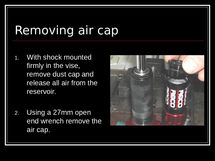
 Removing air cap 1. With shock mounted firmly in the vise, remove dust cap and release all air from the reservoir. 2. Using a 27 mm open end wrench remove the air cap.
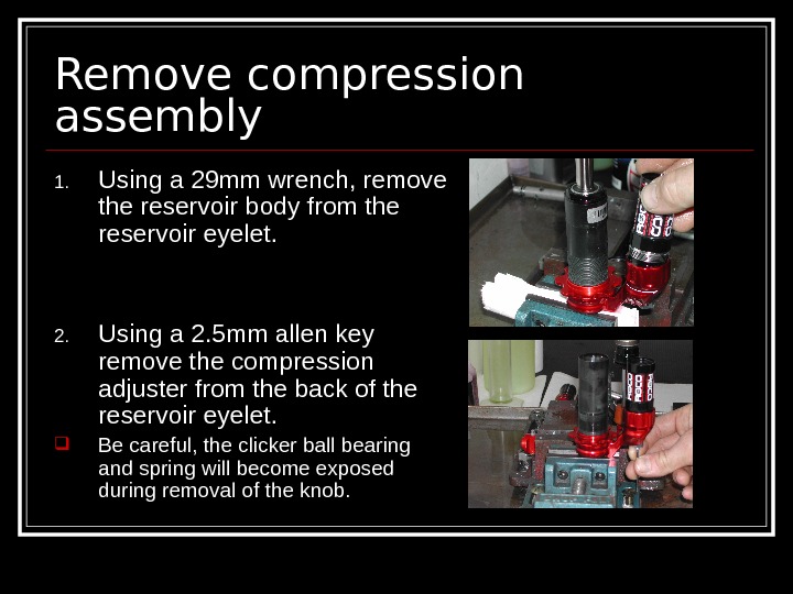
 Remove compression assembly 1. Using a 29 mm wrench, remove the reservoir body from the reservoir eyelet. 2. Using a 2. 5 mm allen key remove the compression adjuster from the back of the reservoir eyelet. Be careful, the clicker ball bearing and spring will become exposed during removal of the knob.
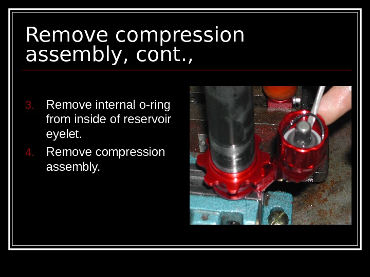
 Remove compression assembly, cont. , 3. Remove internal o-ring from inside of reservoir eyelet. 4. Remove compression assembly.
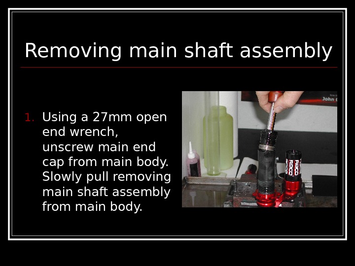
 Removing main shaft assembly 1. Using a 27 mm open end wrench, unscrew main end cap from main body. Slowly pull removing main shaft assembly from main body.
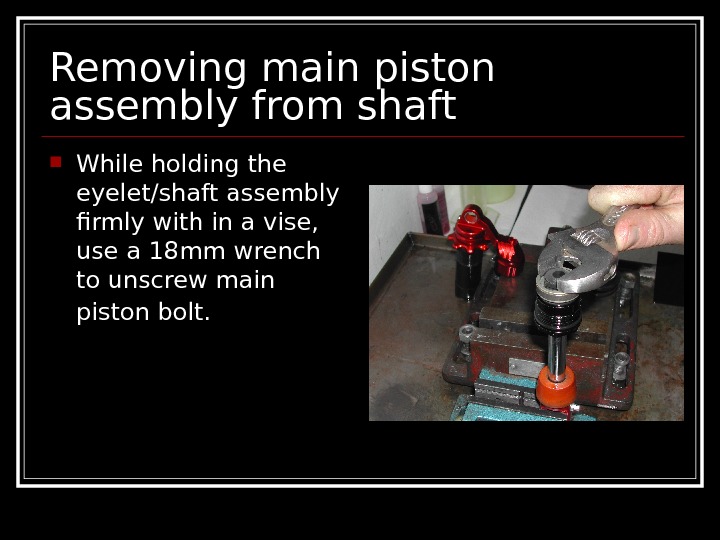
 Removing main piston assembly from shaft While holding the eyelet/shaft assembly firmly with in a vise, use a 18 mm wrench to unscrew main piston bolt.
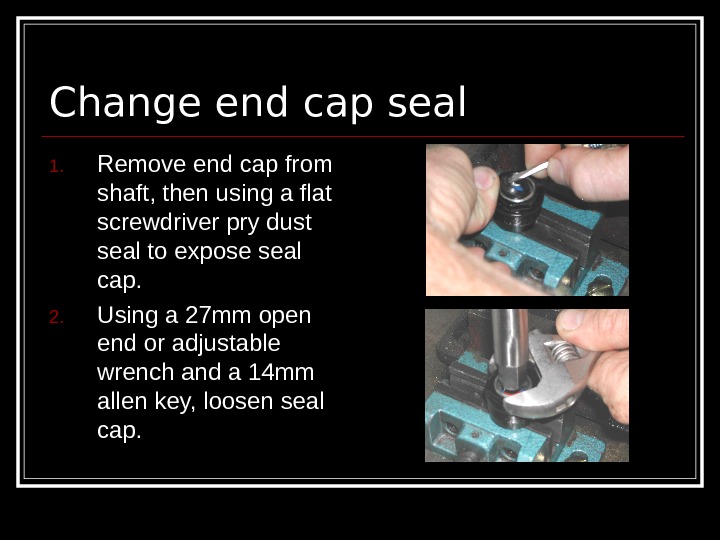
 Change end cap seal 1. Remove end cap from shaft, then using a flat screwdriver pry dust seal to expose seal cap. 2. Using a 27 mm open end or adjustable wrench and a 14 mm allen key, loosen seal cap.
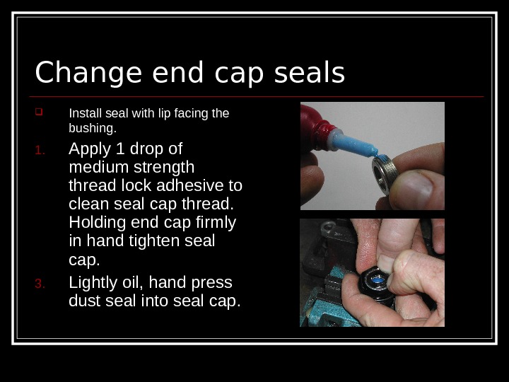
 Change end cap seals Install seal with lip facing the bushing. 1. Apply 1 drop of medium strength thread lock adhesive to clean seal cap thread. Holding end cap firmly in hand tighten seal cap. 3. Lightly oil, hand press dust seal into seal cap.
 Changing shims При смене прокладок на главной поршень, общее количество шайб, а общая толщина все прокладки в сочетании должно оставаться одинаковым. Добавление или изменение прокладки должно быть сделано с большой осторожностью. Если общая толщина прокладок и поршневые компонентов не стоит на месте, корректировка будет осуществляться и / или части могут быть повреждены. Изменение прокладки стеки могут значительно изменять характеристики демпфирования удара. В правой руки обертки стека, изменяя бесконечен для гонщика, так и для свободного наездника.
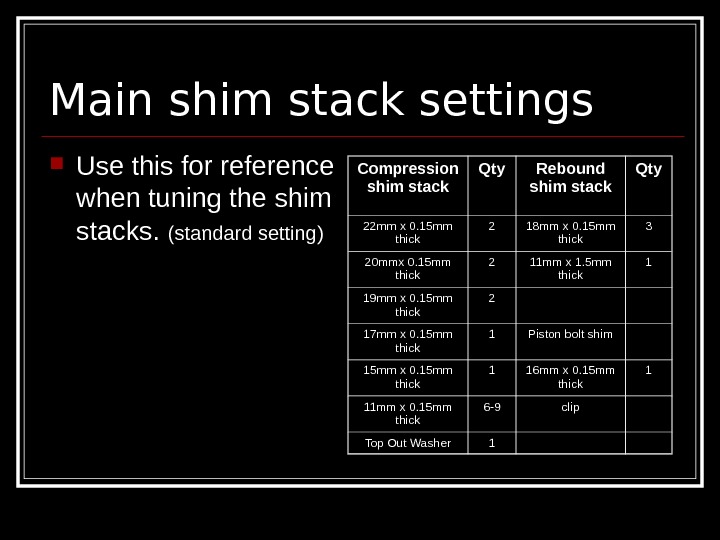
 Main shim stack settings Use this for reference when tuning the shim stacks. (standard setting) Compression shim stack Qty Rebound shim stack Qty 22 mm x 0. 15 mm thick 2 18 mm x 0. 15 mm thick 3 20 mmx 0. 15 mm thick 2 11 mm x 1. 5 mm thick 1 19 mm x 0. 15 mm thick 2 17 mm x 0. 15 mm thick 1 Piston bolt shim 15 mm x 0. 15 mm thick 1 16 mm x 0. 15 mm thick 1 11 mm x 0. 15 mm thick 6 -9 clip Top Out Washer
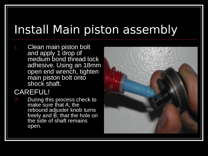
 Install Main piston assembly 1. Clean main piston bolt and apply 1 drop of medium bond thread lock adhesive. Using an 18 mm open end wrench, tighten main piston bolt onto shock shaft. CAREFUL! During this process check to make sure that A; the rebound adjuster knob turns freely and B; that the hole on the side of shaft remains open.
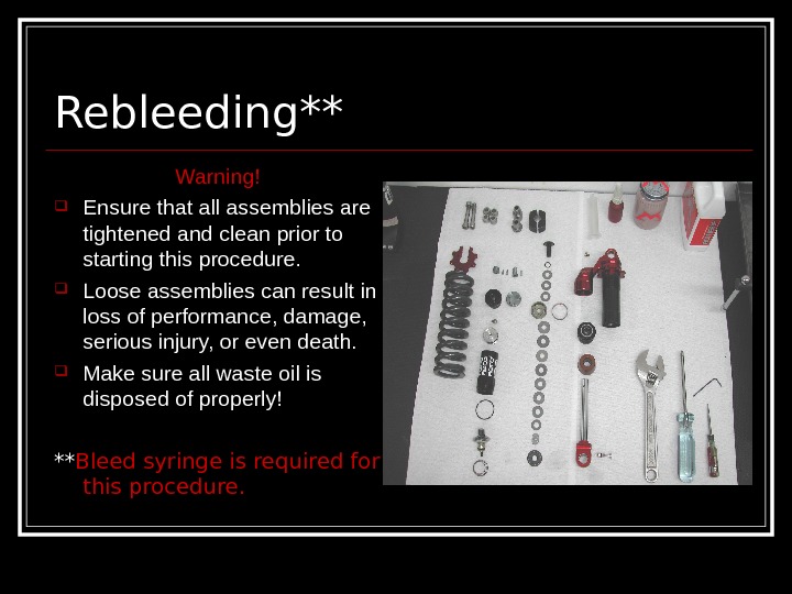
 Rebleeding** Warning! Ensure that all assemblies are tightened and clean prior to starting this procedure. Loose assemblies can result in loss of performance, damage, serious injury, or even death. Make sure all waste oil is disposed of properly! ** Bleed syringe is required for this procedure.
 Shock position For the first part of rebleeding process, the shock should remain fastened vertically to a vise from the reservoir eyelet with the bleed screw installed. Throughout this entire process, work must be performed SLOWLY. The faster you bleed the shock the longer it will take!
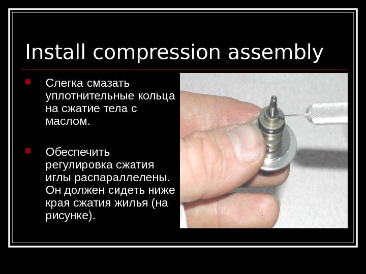
 Install compression assembly Слегка смазать уплотнительные кольца на сжатие тела с маслом. Обеспечить регулировка сжатия иглы распараллелены. Он должен сидеть ниже края сжатия жилья (на рисунке).
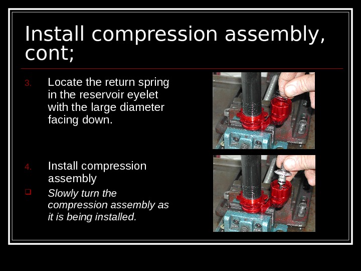
 Install compression assembly, cont; 3. Locate the return spring in the reservoir eyelet with the large diameter facing down. 4. Install compression assembly Slowly turn the compression assembly as it is being installed.
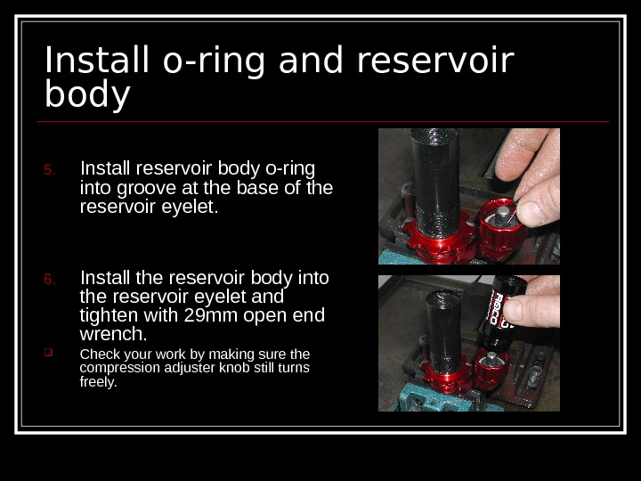
 Install o-ring and reservoir body 5. Install reservoir body o-ring into groove at the base of the reservoir eyelet. 6. Install the reservoir body into the reservoir eyelet and tighten with 29 mm open end wrench. Check your work by making sure the compression adjuster knob still turns freely.
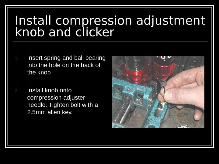
 Install compression adjustment knob and clicker 1. Insert spring and ball bearing into the hole on the back of the knob 2. Install knob onto compression adjuster needle. Tighten bolt with a 2. 5 mm allen key.
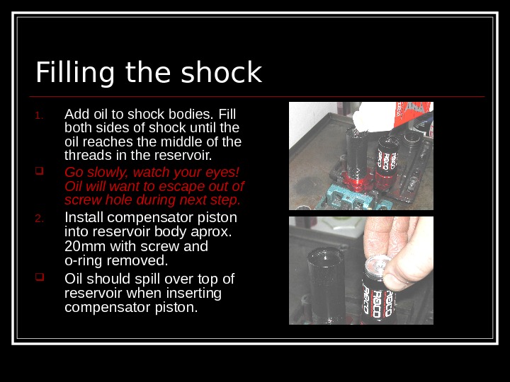
 Filling the shock 1. Add oil to shock bodies. Fill both sides of shock until the oil reaches the middle of the threads in the reservoir. Go slowly, watch your eyes! Oil will want to escape out of screw hole during next step. 2. Install compensator piston into reservoir body aprox. 20 mm with screw and o-ring removed. Oil should spill over top of reservoir when inserting compensator piston.
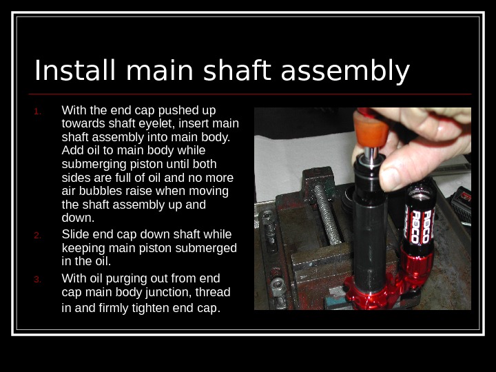
 Install main shaft assembly 1. With the end cap pushed up towards shaft eyelet, insert main shaft assembly into main body. Add oil to main body while submerging piston until both sides are full of oil and no more air bubbles raise when moving the shaft assembly up and down. 2. Slide end cap down shaft while keeping main piston submerged in the oil. 3. With oil purging out from end cap main body junction, thread in and firmly tighten end cap.
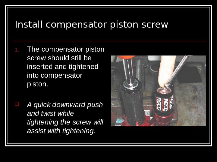
 Install compensator piston screw 1. The compensator piston screw should still be inserted and tightened into compensator piston. A quick downward push and twist while tightening the screw will assist with tightening.
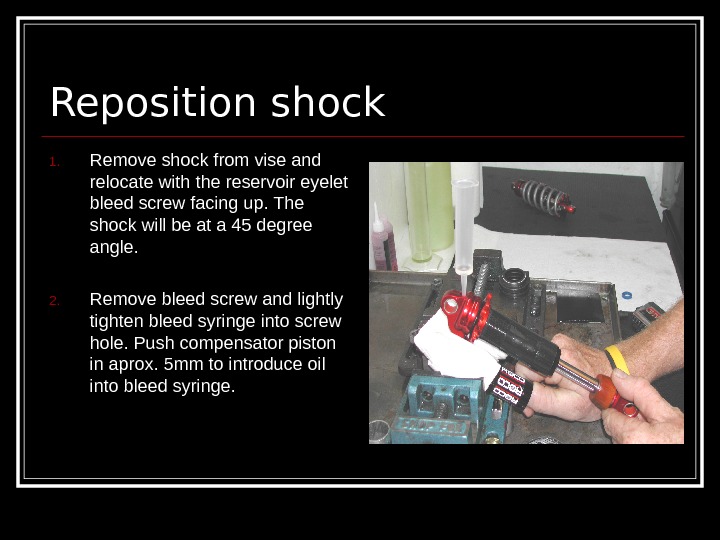
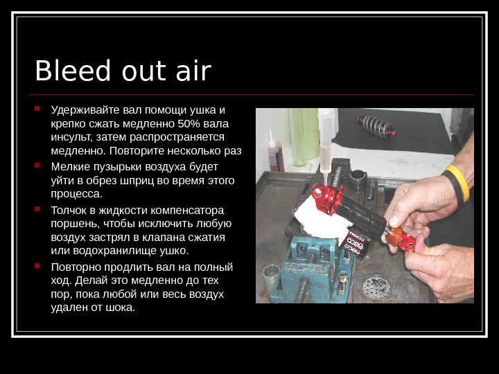
 Reposition shock 1. Remove shock from vise and relocate with the reservoir eyelet bleed screw facing up. The shock will be at a 45 degree angle. 2. Remove bleed screw and lightly tighten bleed syringe into screw hole. Push compensator piston in aprox. 5 mm to introduce oil into bleed syringe.
 Bleed out air Удерживайте вал помощи ушка и крепко сжать медленно 50% вала инсульт, затем распространяется медленно. Повторите несколько раз Мелкие пузырьки воздуха будет уйти в обрез шприц во время этого процесса. Толчок в жидкости компенсатора поршень, чтобы исключить любую воздух застрял в клапана сжатия или водохранилище ушко. Повторно продлить вал на полный ход. Делай это медленно до тех пор, пока любой или весь воздух удален от шока.
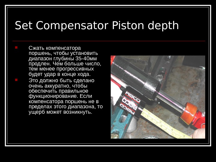
 Set Compensator Piston depth Сжать компенсатора поршень, чтобы установить диапазон глубины 35 -40 мм продлен. Чем больше число, тем менее прогрессивных будет удар в конце хода. Это должно быть сделано очень аккуратно, чтобы обеспечить правильное функционирование. Если компенсатора поршень не в пределах этого диапазона, то ущерб может возникнуть.
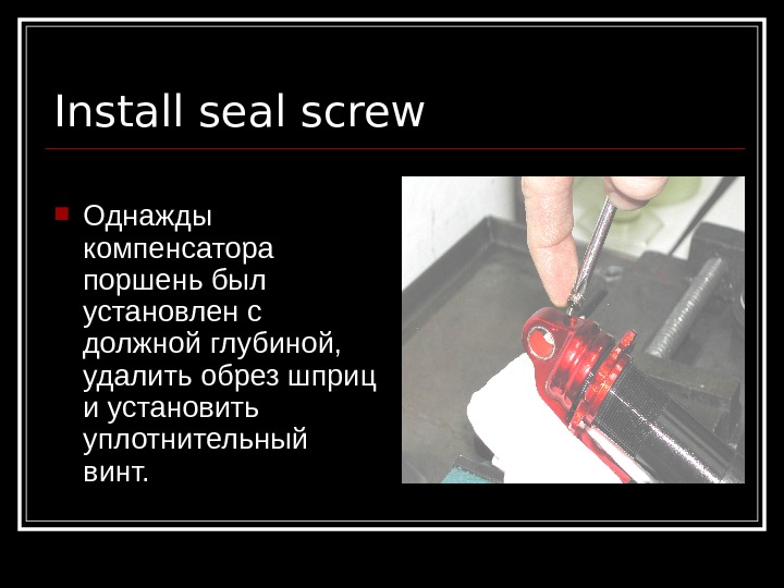
 Install seal screw Однажды компенсатора поршень был установлен с должной глубиной, удалить обрез шприц и установить уплотнительный винт.
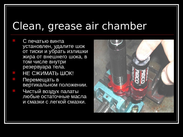
 Clean, grease air chamber С печатью винта установлен, удалите шок от тиски и убрать излишки жира от внешнего шока, в том числе внутри резервуара тела. НЕ СЖИМАТЬ ШОК! Перемещать в вертикальном положении. Чистый воздух палаты любые остаточные масла и смазки с легкой смазки.
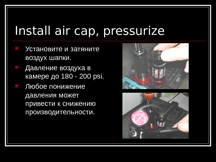
 Install air cap, pressurize Установите и затяните воздух шапки. Давление воздуха в камере до 180 — 200 psi. Любое понижение давления может привести к снижению производительности.
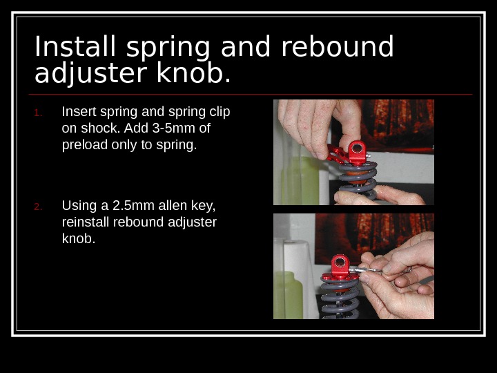
 Install spring and rebound adjuster knob. 1. Insert spring and spring clip on shock. Add 3 -5 mm of preload only to spring. 2. Using a 2. 5 mm allen key, reinstall rebound adjuster knob.
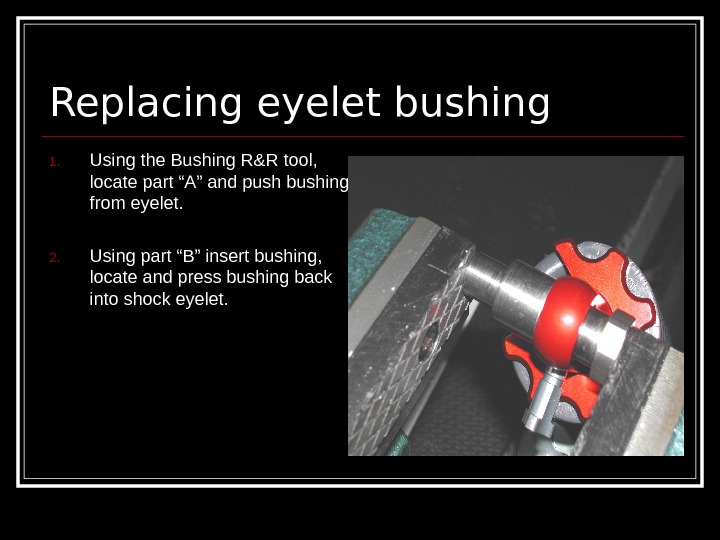
 Replacing eyelet bushing 1. Using the Bushing R&R tool, locate part “A” and push bushing from eyelet. 2. Using part “B” insert bushing, locate and press bushing back into shock eyelet.
 Service kits, tools Rebuild kit (all o-rings and bushings) Part # create code – see excel sheet Shim kit ( 22 -11 mm dia. 0. 15 mm thick ) Part # code # Shim kit ( 22 -11 mm dia. 0. 20 mm thick ) Part # code # Oil (1 liter) 5 wt shock oil Part # create code — Bleeding syringe Part # source in Europe 12. 7 mm shaft soft jaw Part # create part and code # Bushing R&R tool Part # create part and code #
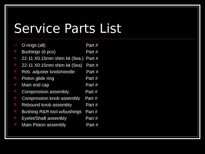
 Service Parts List O-rings (all) Part # Bushings (6 pcs) Part # 22 -11 X 0. 15 mm shim kit (5 ea. ) Part # 22 -11 X 0. 15 mm shim kit (5 ea) Part # Reb. adjuster knob/needle Part # Piston glide ring Part # Main end cap Part # Compression assembly Part # Compression knob assembly Part # Rebound knob assembly Part # Bushing R&R tool w/bushings Part # Eyelet/Shaft assembly Part # Main Piston assembly Part #

