658a6cd7c6b0ad428022999a5e304e11.ppt
- Количество слайдов: 101


Robot Motion • Forward and Inverse Kinematics – Next quarter • PID Control • Frame-Based Motions on the AIBO • Modeling Effects of Motions

Automatic Control Systems, Servos, Automatic Tracking, Feedback Control

VOCABULARY: Automatic Control Systems · Automatic: able to activate, move or regulate itself. · Control: command, direct, rule, check, limit, restrain, regulate or operate. · System: a group or combination of interrelated, independent, or interacting elements forming a collective entity. • Control engineering is concerned with modifying the behavior of dynamical systems to achieve desired goals.

Control System Terminology • Input - Excitation applied to a control system from an external source. • Output - The response obtained from a system • Feedback - The output of a system that is returned to modify the input. • Error - The difference between the input and the output.

Types of Control Systems • Open-Loop · Simple control system which performs its function without concerns for initial conditions or external inputs. · Must be closely monitored. • Closed-Loop (feedback) · Uses the output of the process to modify the process to produce the desired result. · Continually adjusts the process.

Control Systems

Transducer or Sensor Factors

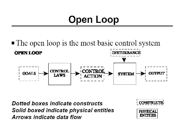
Open Loop Controller
 is a type of")
Open Loop Controller 1. An open-loop controller (or non-feedback controller) is a type of controller which computes its input into a system using only the current state and its model of the system 2. The system does not observe the output of the processes that it is controlling Inpu t Controller Motor Outp ut
 1. Open-loop control is useful for welldefined systems where the")
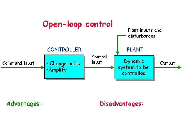
Open Loop Controller (cont…) 1. Open-loop control is useful for welldefined systems where the relationship between input and the resultant state can be modeled by a mathematical formula 2. For example determining the voltage to be fed to an electric motor that drives a constant load, in order to achieve a desired speed would be a good application of openloop control
 1. An open-loop controller is often used in simple processes")
Open Loop Controller (cont…) 1. An open-loop controller is often used in simple processes because of its simplicity and low-cost, especially in systems where feedback is not critical 2. Generally, to obtain a more accurate or more adaptive control, it is necessary to feed the output of the system back to the inputs of the controller

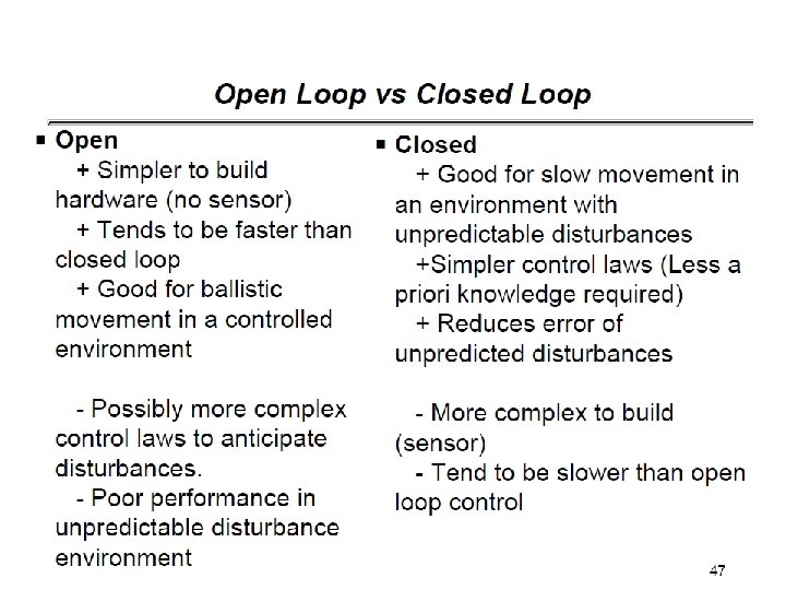
Open-loop control • Advantages: · Stability not a problem · Cheaper than closed-loop · Can be used even if output cannot be measured • Disadvantages: · Changes in system or disturbances ? errors · Periodic calibration required

Closed Loop Controller

Example of a simple Control in Closed Loop

Closed Loop Controller 1. Closed-loop controllers have the following advantages over open-loop controllers: 1. Disturbance rejection (such as unmeasured friction in a motor) 2. Guaranteed performance even with model uncertainties, when the model structure does not match perfectly the real process and the model parameters are not exact

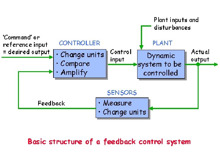
Closed Loop Controller 1. A closed-loop controller uses feedback to control states or outputs of a dynamical system Controller Input Motor Output Measurement Output Feedback 2. Process inputs have an effect on the process outputs, which is measured with sensors and processed by the controller; the result is used as input to the process, closing the loop

The General View of a Control Loop e u

Feedback or Closed Loop System

PID Control • Proportional Integral Derivative Control • The Basic Problem: – We have n joints, each with a desired position which we have specified – Each joint has an actuator which is given a command in units of torque – Most common method for determining required torques is by feedback from joint sensors

What is PID Control? • Proportional, Integral, & Derivative Control – Proportional: Multiply current error by constant to try to resolve error – Integral: Multiply sum of previous errors by constant to resolve steady state error (error after system has come to rest) – Derivative: Multiply time derivative of error change by constant to resolve error as quickly as possible

Feedback Signal is subtracted

Integrated circuit with differential amplifier Motor and gears rotate the wheel Potentiometer on the wheel Feedback Signal is subtracted

Proportional Controller Control Law Step response of the system for proportional control only

Complete PID controller Control Law Step response of the system for proportional plus integral plus derivative (PID) control. Kp = 20 KI = 75 KD = 0 time

Cruise Control

Example V = velocity, speed

All opposing forces Force created by motor Acceleration is derivative of speed

acceleration speed Two terminologies integrator
 control • Advantages: · Reduced sensitivity to: • Disadvantages: · disturbance inputs")
Closed-loop (feedback) control • Advantages: · Reduced sensitivity to: • Disadvantages: · disturbance inputs · Increased complexity and cost · parameter changes · Risk of instability · Can stabilize an open- loop unstable plant · Can change system dynamics: · speed of response · accuracy · reduce effect of non-linearities

Advantages of a Closed-Loop Feedback System • Increased Accuracy · Increased ability to reproduce output with varied input. • Reduced Sensitivity to Disturbance · By self correcting it minimizes effects of system changes. • Smoothing and Filtering · System induced noise and distortion are reduced. • Increased Bandwidth · Produces satisfactory response to increased range of input changes.

In general, the control system is more complex….

Designing control systems is complex Humanoid robot can have more than 43 variables to control … simplified stages of control system design….

Major Types of Feedback Used • Position Feedback · Used when the output is a linear distance or angular measurement. • Rate & Acceleration Feedback · Feeds back rate of motion or rate of change of motion (acceleration) · Motion smoothing · Uses a electrical/mechanical device called an accelerometer

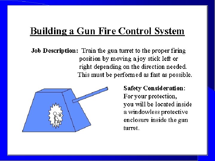
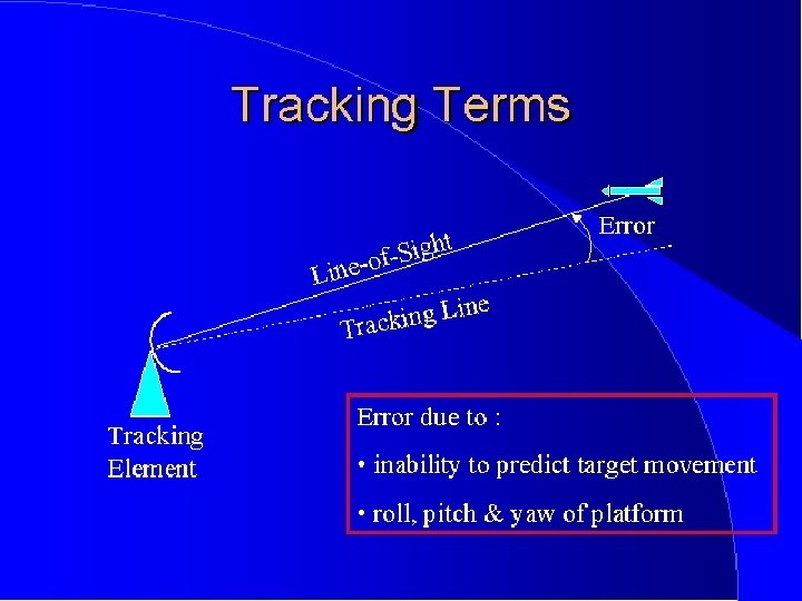
Target Tracking

In unstable system the periodic component would not disappear

Target Tracking Parameters • • Azimuth Elevation Range Relative Target Velocity · Target’s motion with respect to the platform’s motion

Five Basic Functions of Angle. Tracking Servo Systems • Sense position error (magnitude and direction) • Provide position feedback • Provide velocity feedback • Provide data smoothing / stabilization • Provide a power-driving device

Uses of Angle-Tracking Servo Systems • Monotrack fire control radars • Homing missiles • Acoustic homing torpedoes • Aviation fire control tracking systems

Motion Control System

1. Scope of Study 2. Servo System 3. Mechanical Transmission 4. Applications Motion Control System • The primary purpose of the servo system is to control the motion of the load Motion Requirements Servo System Mechanical transmission

Motion Control System - Principles • The digital ac servo system is typically available with three modes of operation: – Torque Control Mode • In other words, in order to control the position the torque and velocity should be controlled. – Velocity Control Mode – Position Control Mode Motion Requirements Servo System Mechanical Transmission

Motion Control System Example 2. Speed Regulator 1. Position Regulator 3. AC Motor Electronic commutator Desired output Position feedback Speed feedback The ac servo system consists of five major components. 5. Position Sensor AC supply 4. Power Converter

Motion Control System • Most applications are more complicated than directly driving load. – Common mechanical transmissions include : • • • timing belts, gears, conveyors, leadscrews, and rack & pinion mechanism. – Especially, the timing belt and gearbox can be utilized as a speed reducer, and the other are to be used as translators.

Motion Control System with linear motion Change to linear motion…. . . • For instance, if the application requires linear motion of the load: – a leadscrew, – rack & pinion, or – conveyor is used to translate the motor’s rotary motion into linear motion. Load Tacle Motor Coefficient of friction Optional Timing Belt or Gear Reducer Ball Nut Ball Screw

Linear Servo Systems Application of linear servo system: box packing

Troubles in Control Systems

Actuator Hysteresis

Mechanical Hysteresis

Mechanical Hysteresis - backlash

Friction

Electronic Hysteresis

Sony AIBO Robot Joint Angle Limits

Intelligent Complete Robot Perception Cognition Sensors Action Actuators External World

What is good about robots like AIBO? • These concepts make up the low level functionality of the AIBO • Implemented once and used repeatedly • For more information about PID Control and Forward & Inverse Kinematics take Matt Mason’s Robotic Manipulation course

AIBO Actuators • 18 degrees of freedom with a continuously controllable range of motion – – 3 DOF in each leg (12 total) 3 DOF in the head 2 DOF in the tail 1 DOF in the jaw • Each joint is controlled by specifying to a desired joint angle to OVirtual. Robot. Comm. • 2 binary motors for the ears • A speaker for general sound production

Motor Control • Each message to OVirtual. Robot. Comm contains a set of target angles for the joints – Each target is used for a PID controller (part of the OS) that controls each motor – Each target angle is used for one 8 ms motor frame • Each message contains at least 4 motor frames (32 ms)

The Motion Interface Dynamic Walking Motion Static Frame-Based Motion Frames Walk Engine Frame Interpolator

Frame-Based Motion • Each motion is described by a series of “frames” which specify the position of the robot, and a time to interpolate between frames • Movement between frames is calculated through linear interpolation of each joint

Kicking • A series of set positions for the robot • Linear interpolation between the frames – Kinematics and interpolation provided by CMWalk. Engine • Set robot in desired positions and query the values of the joints

Use of Kicks in Behaviors • Modeling effects of kicking motions – Ball vision analysis – Ball trajectory angle analysis – Kick strength analysis • Kick selection for behaviors – Selection algorithm – Performance comparison

Kick Selection • Incorporate the kick models into the selection algorithm – The robot knows its position on the field relative to the goal and the desired ball trajectory – The robot selects appropriate kick by referencing the kick model – If no kick fits desired criteria, robot selects closest matching kick and turns/dribbles ball to appropriate position

Frame-Based Motion

Frame-Based Motion • Each motion is described by a series of “frames” which specify the position of the robot, and a time to interpolate between frames • Movement between frames is calculated through linear interpolation of each joint
); Head. Ang(b, 0. 5, 1. 5,")
Examples: Valid Motion Frames Body. Pos(b, 98, RAD(16)); Head. Ang(b, 0. 5, 1. 5, 0. 0); Leg. Pos(b, 0, 123, 85, 0); Leg. Pos(b, 1, 123, -85, 0); Leg. Ang(b, 2, 0. 1, 0. 0, 0. 2); Leg. Ang(b, 3, 0. 1, 0. 0, 0. 2); m[n]. body = b; m[n]. time = 100; n++; Leg. Ang(b, 0, 0. 0, 1. 5, 0. 0); Leg. Ang(b, 1, 0. 0, 1. 5, 0. 0); Leg. Ang(b, 2, 0. 1, 0. 0, 0. 2); Leg. Ang(b, 3, 0. 1, 0. 0, 0. 2); m[n]. body = b; m[n]. time = 100; n++; Body. Pos(b, 98, RAD(16)); Head. Ang(b, 0. 5, 1. 5, 0. 0); Mouth. Ang(b, -. 7); Leg. Pos(b, 0, 123, 85, 0); Leg. Pos(b, 1, 123, -85, 0); Leg. Pos(b, 2, -80 , 75, 0); Leg. Pos(b, 3, -80 , -75, 0); m[n]. body = b; m[n]. time = 100; n++;

Defining a Frame • The position of the robot in each frame can be described using any of the following: – Position of the legs - in terms of angles of each joint or position of the foot in motion coordinates – Angle of the head (tilt, pan, roll) – Body height and angle struct Body. State{ Body. Position pos; – Angle of the mouth Leg. State leg[4]; Head. State head; Mouth. State mouth; };

Questions and Problems to Solve

What did we learn? Problem 1 • Feedback control is a fundament of robot control • Various kits (Lego Dacta Control Lab) have several demonstrations and project to explain the principles of feedback: – Line following – Speed control – Temperature control (fan, lamp, sensor) • Find on internet some of these kits and explanations of projects for high school.

What did we learn? Problem 2 • Control of Many DOF robots is tough • In addition to classical and modern control theory we use: – – fuzzy control genetic algorithms neural control bio-mimetic systems • Review your control knowledge (for next quarter), but remember that in this class all knowledge is through programming. • Describe a simple robot arm which uses fuzzy logic and a motor. • Describe a mobile robot that uses a genetic algorithm and a motor. How FGA is used in relation to a motor?

Your task Problem 3 • Learn about the particular servo that you plan to use. If the servo was not suggested by the professor, learn about servos that are available, calculate your project requirements for a servo and pick one. The more servos we order, the cheaper the price of one. • If you do not want to use one of standard servos, your choices are: – build your own servo from a DC motor. This is a big project by itself and you must have clear reasons to do so – Use stepper motor. Remember that they are slow and weak, why you want to use them? You must be sure of your reasons

Problem 4 Your task • Use hydraulic control. Why? You need to purchase or build your own actuator. Think about redesigning our horse leg with better syringes and oil instead of water. How can you connect the syringe to a stepper motor? Problem 5 Use pneumatic control. Read first the documentation of pneumatic hand or old Electric Horse. Talk to designers. – Find pistons in Mondo-Tronics or other robot store. They are good. Problem 6 • Use Nintinol or other similar actutors. They are good for face muscles or similar small and weak movements. – Can they be used for a hexapod? I doubt, but try to convince me – Before you do this, read the two-volume book of Conrad and Mills

Formulas & Units useful to solve practical problems with motors and gears • Unit conversions of interest – – – 1 lbs = 4. 45 N 1 inch = 0. 0254 meters 1 in-lbs = 0. 11 N-m 1 RPM = 60 Rev / Hour = 0. 105 Rad / Sec 1 mile = 5280 X 12 inches = 63, 000 inches • Power = Force (N) X Velocity (m/s) • Power = Torque (N-m) X Angular Velocity (Rad/Sec) • Electrical Power = Voltage X Current
")
Problems with Motor Characteristics Problem 7 Stall Current – – Stall Torque (T 0) Stall Current (A 0) Free Speed (Wf) Free Current (Af) 1. Find these data for the motors that you use. 2. Calculate the torque of your robot arm or mobile robot to solve problems that you want. 3. Draw the Torque vs Speed Curve for your motor and check if this is what you expect. Torque, Current • Torque v Speed Curves T 0 K (slope) A 0 Af Speed Wf Free Current
 X=Motor Speed b=Stall Torque (T 0)")
• • Y=Motor Torque m=K (discuss later) X=Motor Speed b=Stall Torque (T 0) Torque, Current Slope-Intercept (Y=m. X + b) T 0 K (slope) A 0 Af Speed Wf What is K? … It is the slope of the line. Slope = change in Y / change in X = (0 - T 0)/(Wf-0) = -T 0/Wf K = Slope = -T 0/Wf How to calculate slope when the characteristic is not linear?

• • Y=Motor Torque m=K = -T 0/Wf X=Motor Speed b=Stall Torque = T 0 Torque, Current (Y=m. X + b) Continued. . . T 0 (b) K (-T 0/Wf) A 0 Af Speed Equation for a motor: Torque = (-T 0/Wf) * Speed + T 0 How to calculate torque in any point of the characteristic curve? Wf

• What are cutoff Amps? – Max useable amps – Limited by breakers – Need to make assumptions Torque, Current (Amps) and FIRST Can our Motors operate above 30 amps? T 0 A 0 Cutoff Amps Af Speed Wf - Absolutely, but not continuous. When designing, you want to be able to perform continuously; so finding motor info at 30 amps could prove to be useful.

• T 30 = Torque at 30 Amps • W 30 = Speed at 30 Amps Current Equation: Current = (Af-A 0)/Wf * Speed + A 0 Torque, Current Torque at Amp Limit T 0 A 0 Cutoff Amps Af Motor Equation: Torque = (-T 0/Wf) * Speed + T 0 S @ 30 A (W 30) = (30 - A 0) * Wf / (Af-A 0) T @ 30 A (T 30) = (-T 0/Wf) * W 30 + T 0 Speed Wf

Power = Torque * Speed Must give up torque for speed Max Power occurs when: T = T 0/2 & W=Wf/2 What if max power occurs at a current higher than 30 A? Torque, Current Power - Max vs. 30 Amps Power T 0 Af Speed Wf Paul’s Tip #1: Design drive motor max power for 30 A! Power is Absolute - It determines the Torque - Speed tradeoff!

Motor Comparisons Let’s Look at Some FIRST Motors 1. Chiaphua Motor 2. Drill Motor 3. Johnson Electric Fisher-Price Motor We will compare T 0, Wf, A 0, Af, T 30, W 30, max power (Pmax), amps @ max power (Apmax), and power at 30 amps (P 30). We will be using Dr. Joe’s motor spreadsheet updated to handle the new motors.

Motor Comparisons We will be using Dr. Joe’s motor spreadsheet updated to handle the new motors. Motor Equations: 1. Fisher-Price: T = (-0. 51/20, 000) * W + 0. 51 2. Bosch Drill: T = (-0. 65/20, 000) * W + 0. 65 3. Chiaphua: T = (-2. 2/5, 500) * W + 2. 2

Combining Motors Using multiple motors is common for drive trains. We will look at matching the big 3 motors. I try to match at free speed, but you can match at any speed you like!! FP and drill will match 1: 1 Wf FP(drill) / Wf Chiaphua = 20000/5500 = 40/11 Gear ratio to match Chip & FP(drill) is 40/11. We will use an efficiency of 95% for the match gear. More to come on Gear Ratio & Efficiency in the Second Half!
")
Combined Motor Data Motor Equations: 1. F-P & Drill: T = (-1. 16/20, 000) * W + 1. 16 2. F-P & Chip: T = (-3. 96/5, 500) * W + 3. 96 3. Drill & Chip: T = (-4. 45/5, 500) * W + 4. 45 4. F-P, Drill, & Chip: T = (-6. 21/5, 500) * W + 6. 21

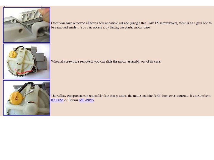
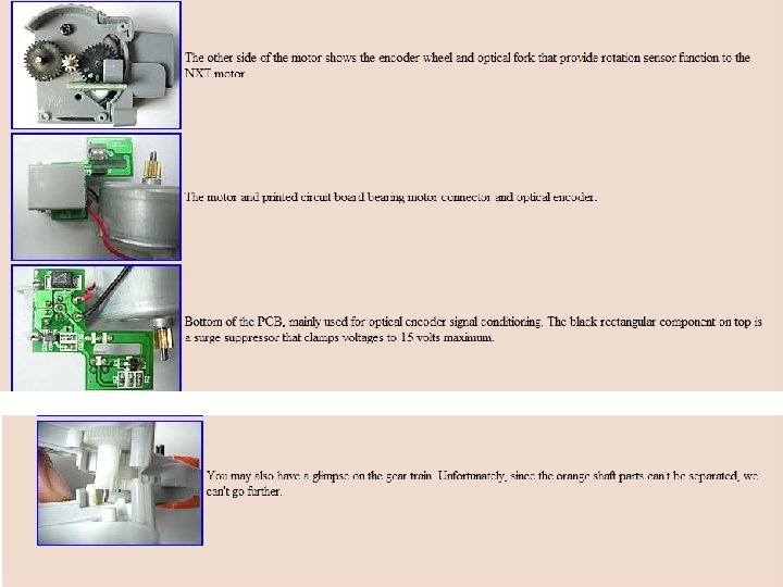
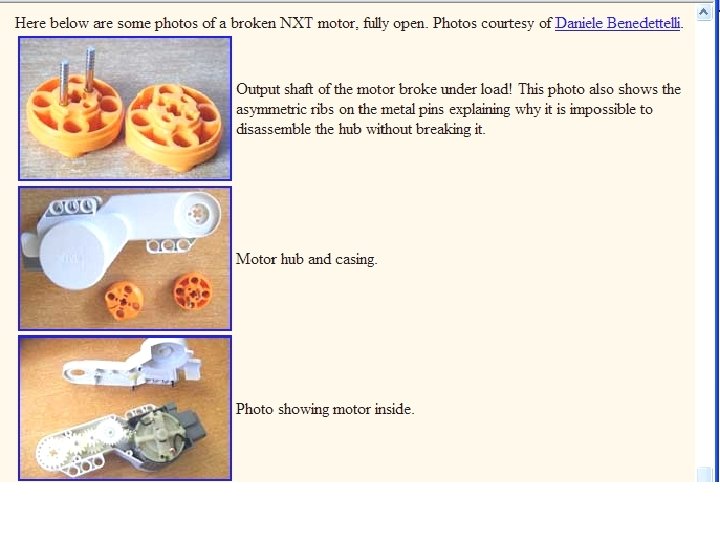
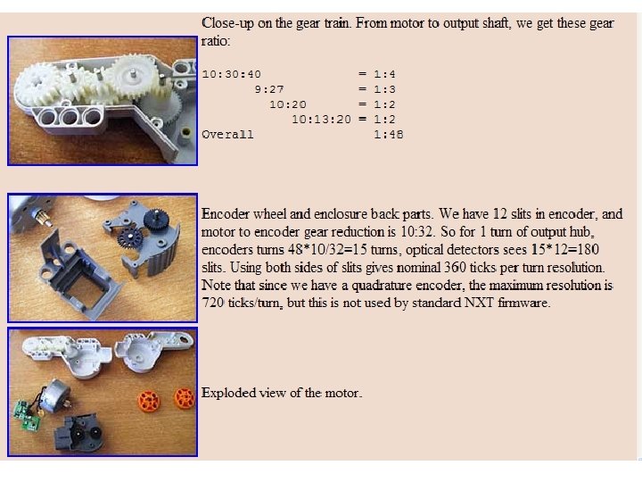
NXT® motor internals for calculations Center of Mass of Lego Motors

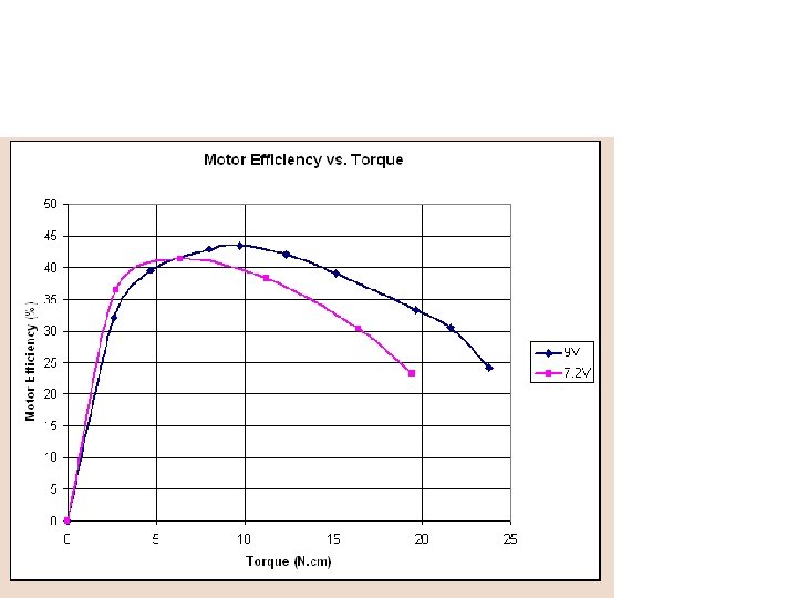
NXT motor characteristics

• The following charts show the characteristics of the NXT motor versus applied load. • For the dark blue curves, the NXT was powered at 9 V (voltage of alkaline batteries), the magenta ones were obtained at 7. 2 V (voltage of Ni. MH batteries). • Power level is 100% for all charts.

• • This curve shows that the maximum mechanical power is obtained at a torque load of about 15 N. cm. If you compare to the curves obtained for the RCX with 71427 motor, you see that the available mechanical power is much higher, almost 4 times! Even powered with 7. 2 V Ni. MH batteries, the NXT can deliver more power than a RCX output with 2 paralleled motors and 9 V supply. This comes with a price of course, the current drained at that power level is much higher - you better have good batteries. . .
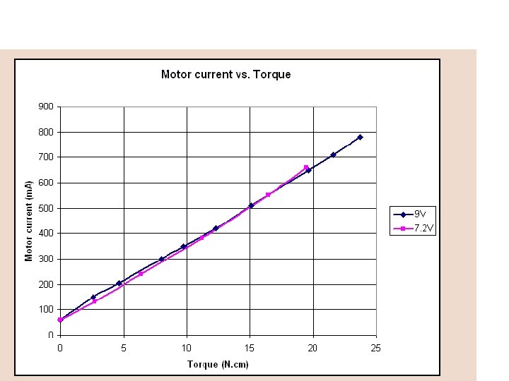

• The current vs. torque shows a linear increase with the load. • Because of power limitations in NXT driver, and thermistor trip current in NXT motor, I suggest that you don't exceed a 15 N. cm torque for extended time periods. • Higher loads (thus current drains) are possible for short periods, but the protections will soon reduce current and available power

Sources Manuela Veloso Paul E. Rybski
658a6cd7c6b0ad428022999a5e304e11.ppt