
RN 28176 EN 14 GLN 01 © NSN


- Размер: 1 Mегабайта
- Количество слайдов: 48
Описание презентации RN 28176 EN 14 GLN 01 © NSN по слайдам
RN 28176 EN 14 GLN 01 © NSN Siemens Networks. BSS S 14 GPRS/EGPRS Integration in BS
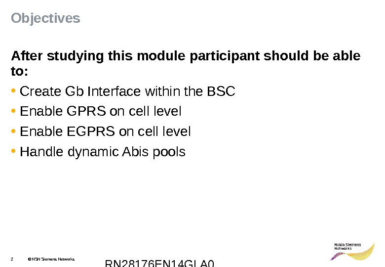
RN 28176 EN 14 GLA 02 © NSN Siemens Networks. Objectives After studying this module participant should be able to: • Create Gb Interface within the BSC • Enable GPRS on cell level • Enable EGPRS on cell level • Handle dynamic Abis pools
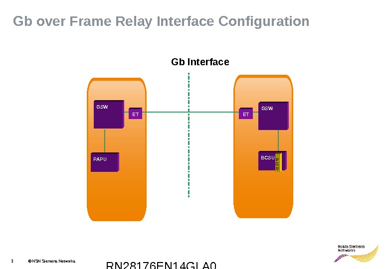
RN 28176 EN 14 GLA 03 © NSN Siemens Networks. Gb over Frame Relay Interface Configuration Gb Interface PAPU ET GSW BCSUET P C UGSW
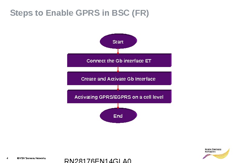
RN 28176 EN 14 GLA 04 © NSN Siemens Networks. Steps to Enable GPRS in BSC (FR) Connect the Gb interface ET Create and Activate Gb Interface Activating GPRS/EGPRS on a cell level End. Start
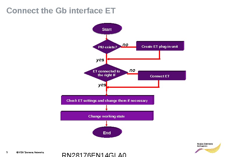
RN 28176 EN 14 GLA 05 © NSN Siemens Networks. Connect the Gb interface ET no yes PIU exists? Start Check ET settings and change them if necessary Connect ETno yes Change working state Create ET plug-in unit. Start ET connected to the right IF Change working state End
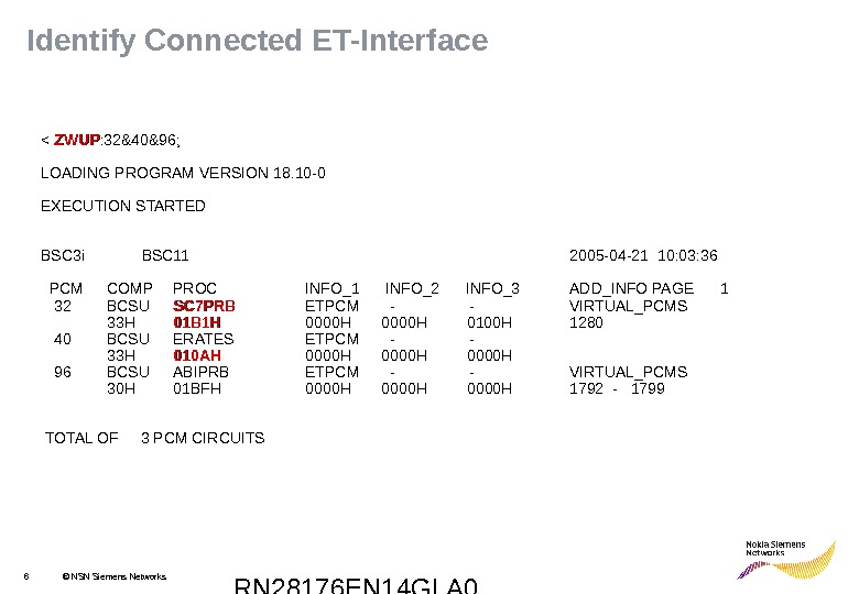
RN 28176 EN 14 GLA 06 © NSN Siemens Networks. Identify Connected ET-Interface < ZWUP : 32&40&96; LOADING PROGRAM VERSION 18. 10 -0 EXECUTION STARTED BSC 3 i BSC 11 2005 -04 -21 10: 03: 36 PCM COMP PROC INFO_1 INFO_2 INFO_3 ADD_INFO PAGE 1 32 BCSU SC 7 PRB ETPCM — VIRTUAL_PCMS 33 H 01 B 1 H 0000 H 0100 H 1280 40 BCSU ERATES ETPCM — 33 H 010 AH 0000 H 96 BCSU ABIPRB ETPCM — VIRTUAL_PCMS 30 H 01 BFH 0000 H 1792 — 1799 TOTAL OF 3 PCM CIRCUITS
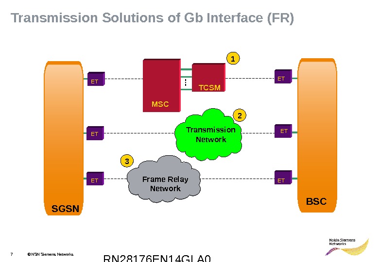
RN 28176 EN 14 GLA 07 © NSN Siemens Networks. Transmission Solutions of Gb Interface (FR) Transmission Network BSCTCSM MSC Frame Relay N etwork SGSN 1 2 3 ET ET ET
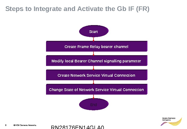
RN 28176 EN 14 GLA 08 © NSN Siemens Networks. Steps to Integrate and Activate the Gb IF (FR) Create Frame Relay bearer channel Modify local Bearer Channel signalling parameter Create Network Service Virtual Connection End. Start Change State of Network Service Virtual Connection
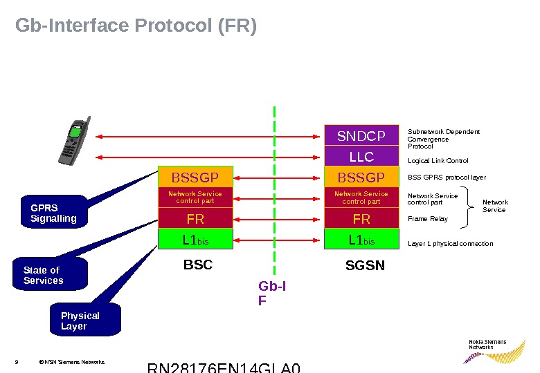
RN 28176 EN 14 GLA 09 © NSN Siemens Networks. Gb-Interface Protocol (FR) SGSNBSC L 1 bis. BSSGP LLCSNDCP FRNetwork Service control part Gb-I F Network Service. Subnetwork Dependent Convergence Protocol Layer 1 physical connection. Logical Link Control BSS GPRS protocol layer Frame Relay. Network Service control part Physical Layer. State of Services GPRS Signalling Network Service control part L 1 bis. BSSGP FRNetwork Service control part
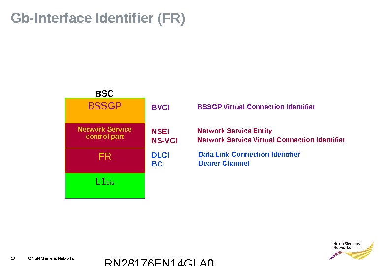
RN 28176 EN 14 GLA 010 © NSN Siemens Networks. Gb-Interface Identifier (FR) NSEI NS-VCI Network Service Entity Network Service Virtual Connection Identifier. BVCI DLCI BCBSC BSSGP Virtual Connection Identifier Data Link Connection Identifier Bearer Channel L 1 bis. BSSGP FRNetwork Service control part
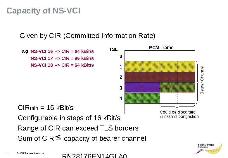
RN 28176 EN 14 GLA 011 © NSN Siemens Networks. Capacity of NS-VCI Given by CIR (Committed Information Rate) e. g. NS-VCI 16 —> CIR = 64 k. Bit/s NS-VCI 17 —> CIR = 96 k. Bit/s NS-VCI 18 —> CIR = 64 k. Bit/s Could be discarded in case of congestion 1 2 3 40 TSL PCM-frame. Bearer C hannel CIR min = 16 k. Bit/s Configurable in steps of 16 k. Bit/s Range of CIR can exceed TLS borders Sum of CIR capacity of bearer channel
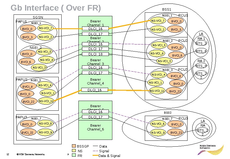
RN 28176 EN 14 GLN 012 © NSN Siemens Networks PCU 2 PCU 1 PCU 3 BTS_6 RA 1 BTS_8 BTS_2 2 RA 2 LA PCU 3 BTS_2 2 RA LABearer Channel_5 Bearer Channel_6 Bearer Channel_2 Bearer Channel_1 Bearer Channel_3 Bearer Channel_4 Gb Interface ( Over FR) DLCI_16 DLCI_17 DLCI_18 DLCI_16 BVCI_3 BVCI_0 NS-VCI_7 NS-VCI_2 NSEI_1 NS-VCI_5 NS-VCI_8 NS-VCI_3 BVCI_0 BVCI_6 NSEI_2 NS-VCI_4 NS-VCI_11 BVCI_8 BVCI_0 NSEI_3 BVCI_22 BVCI_0 NS-VCI_6 NS-VCI_9 NSEI_7 BVCI_3 BVCI_0 NS-VCI_7 NS-VCI_2 NS-VCI_5 NS-VCI_8 NS-VCI_3 BVCI_0 BVCI_6 NSEI_1 NSEI_2 NS-VCI_4 NS-VCI_11 BVCI_8 BVCI_0 NSEI_3 BVCI_22 BVCI_0 NS-VCI_6 NS-VCI_9 NSEI_7 PAPU 1 PAPU 2 PAPU 3 SGSN BSSGP NS FR Data Signal Data & Signal BSS 2 BSS
RN 28176 EN 14 GLN 013 © NSN Siemens Networks Bearername=__________________________Bearer. ID=______ PCM= ____ TSL________ Bearer Rate=_____ NSVCI=____ DLCI=_____ CIR=_____PAPU NS-VCI=___ NS-VC=___SGSN NS-VCI=___ Name _____ NSEI____ NS-VCI=___ Name _____BSC NS-VCI=___ Name _____ NSEI________ NSEI____ BCSU=_____ PCU index= _____Exercise: Read out Gb IF configuration (FR)
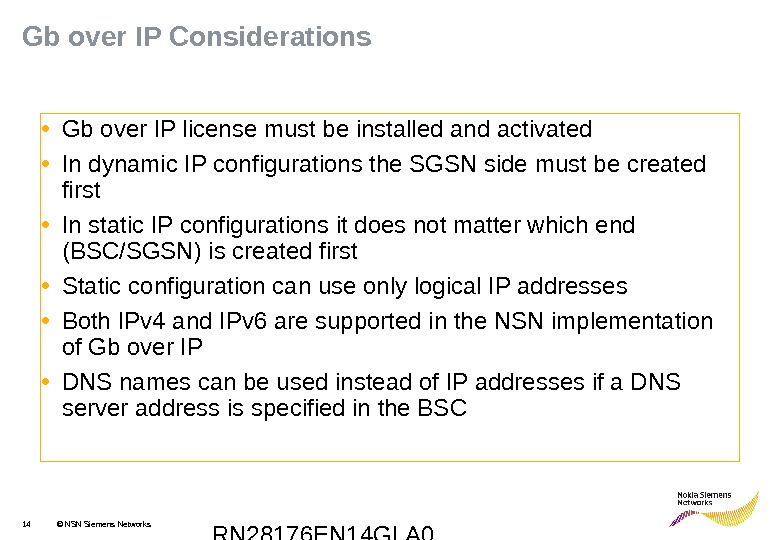
RN 28176 EN 14 GLA 014 © NSN Siemens Networks. Gb over IP Considerations • Gb over IP license must be installed and activated • In dynamic IP configurations the SGSN side must be created first • In static IP configurations it does not matter which end (BSC/SGSN) is created first • Static configuration can use only logical IP addresses • Both IPv 4 and IPv 6 are supported in the NSN implementation of Gb over IP • DNS names can be used instead of IP addresses if a DNS server address is specified in the BS
RN 28176 EN 14 GLA 015 © NSN Siemens Networks. Gb over IP interface configuration (BSC 2 i) Gb Interface PAPU BCSU P C USGSN BSC 2 i IP Networks. PAPUSGSN External LAN
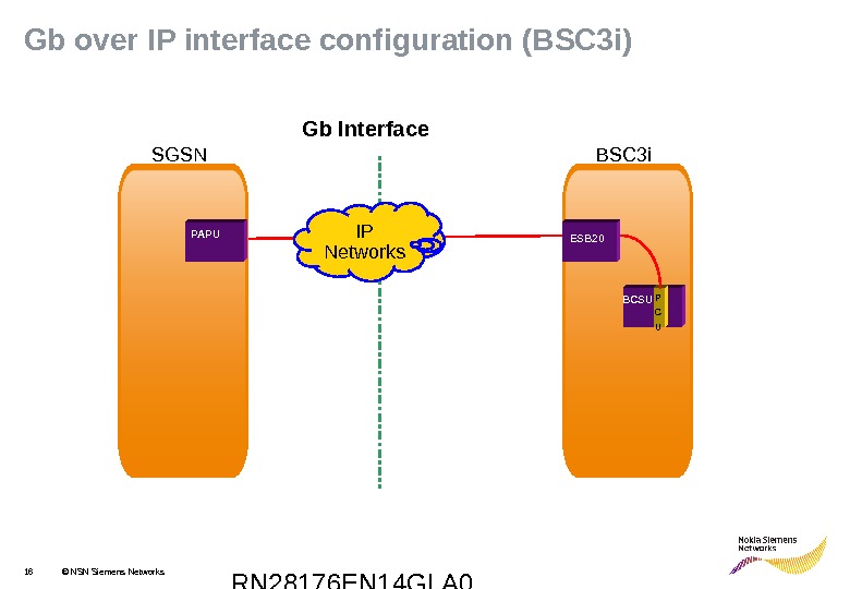
RN 28176 EN 14 GLA 016 © NSN Siemens Networks. Gb over IP interface configuration (BSC 3 i) Gb Interface PAPU BCSU P C USGSN BSC 3 i IP Networks. PAPUSGSN ES
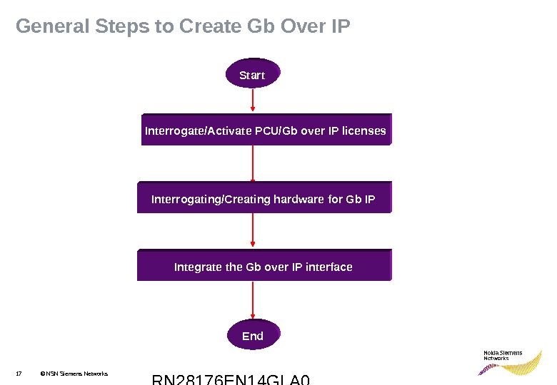
RN 28176 EN 14 GLA 017 © NSN Siemens Networks. General Steps to Create Gb Over IP Interrogate/Activate PCU/Gb over IP licenses Interrogating/Creating hardware for Gb IP Integrate the Gb over IP interface Start End
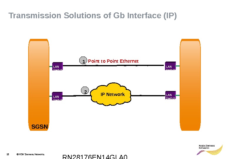
RN 28176 EN 14 GLA 018 © NSN Siemens Networks LAN Switch IP Network Point to Point Ethernet 21 SGSN BSCTransmission Solutions of Gb Interface (IP) LAN Switch
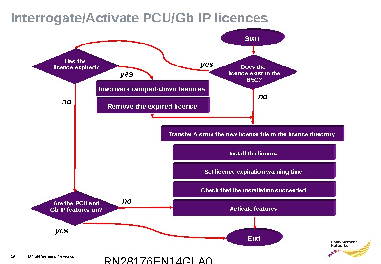
RN 28176 EN 14 GLA 019 © NSN Siemens Networks. Interrogate/Activate PCU/Gb IP licences Install the licence Set licence expiration warning time Check that the installation succeeded Activate features Start Transfer & store the new licence file to the licence directory End. Are the PCU and Gb IP features on? Does the licence exist in the BSC? Inactivate ramped-down features Remove the expired licence noyes no yes Has the licence expired?
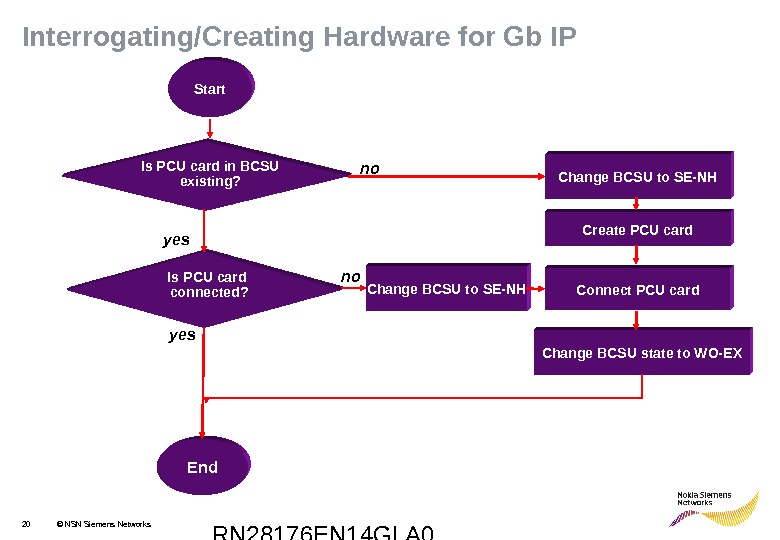
RN 28176 EN 14 GLA 020 © NSN Siemens Networks Change BCSU to SE-NHInterrogating/Creating Hardware for Gb IP Start Create PCU card Connect PCU card Change BCSU state to WO-EX End. Is PCU card in BCSU existing? Is PCU card connected? Change BCSU to SE-NH yes no no
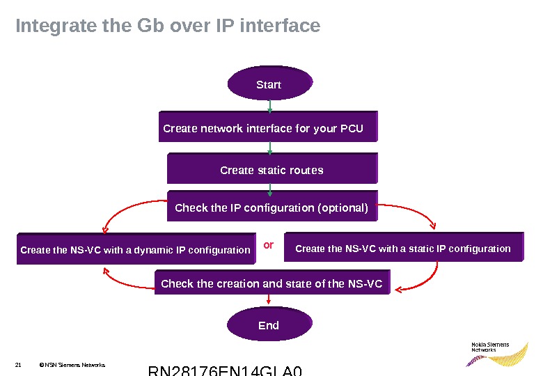
RN 28176 EN 14 GLA 021 © NSN Siemens Networks. Integrate the Gb over IP interface End. Create network interface for your PCU Create static routes Check the IP configuration (optional) Start Create the NS-VC with a dynamic IP configuration Create the NS-VC with a static IP configuration Check the creation and state of the NS-VC or
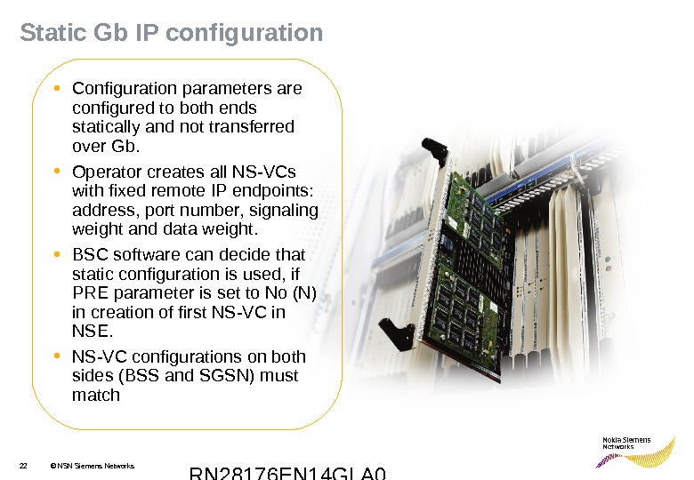
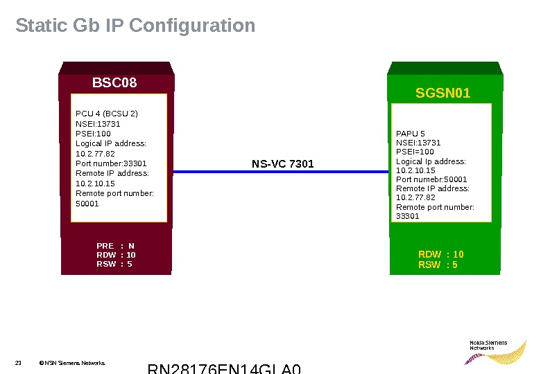
RN 28176 EN 14 GLA 022 © NSN Siemens Networks. Static Gb IP configuration • Configuration parameters are configured to both ends statically and not transferred over Gb. • Operator creates all NS-VCs with fixed remote IP endpoints: address, port number, signaling weight and data weight. • BSC software can decide that static configuration is used, if PRE parameter is set to No (N) in creation of first NS-VC in NSE. • NS-VC configurations on both sides (BSS and SGSN) must match
RN 28176 EN 14 GLA 023 © NSN Siemens Networks. Static Gb IP Configuration PCU 4 (BCSU 2) NSEI: 13731 PSEI: 100 Logical IP address: 10. 2. 77. 82 Port number: 33301 Remote IP address: 10. 2. 10. 15 Remote port number: 50001 PAPU 5 NSEI: 13731 PSEI=100 Logical Ip address: 10. 2. 10. 15 Port numebr: 50001 Remote IP address: 10. 2. 77. 82 Remote port number: 33301 NS-VC 7301 PRE : N RDW : 10 RSW : 5 BSC 08 SGSN 01 RDW : 10 RSW :
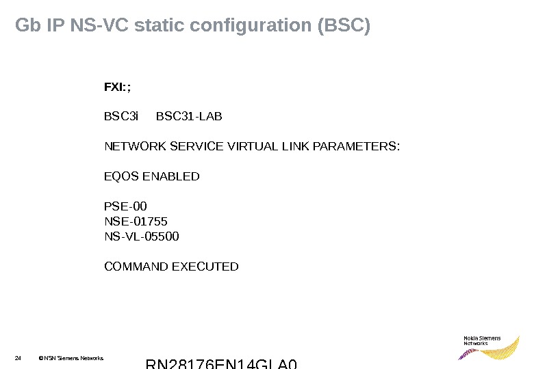
RN 28176 EN 14 GLA 024 © NSN Siemens Networks. Gb IP NS-VC static configuration (BSC) FXI: ; BSC 3 i BSC 31 -LAB NETWORK SERVICE VIRTUAL LINK PARAMETERS: EQOS ENABLED PSE-00 NSE-01755 NS-VL-05500 COMMAND EXECUT
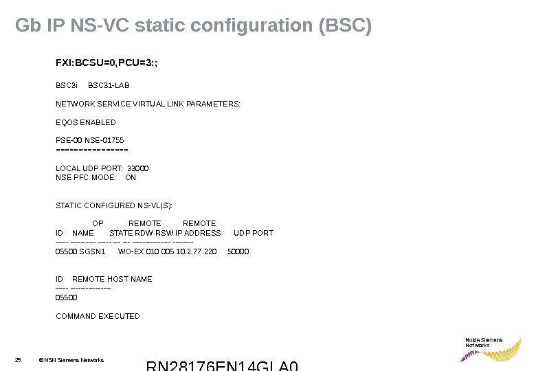
RN 28176 EN 14 GLA 025 © NSN Siemens Networks. Gb IP NS-VC static configuration (BSC) FXI: BCSU=0, PCU=3: ; BSC 3 i BSC 31 -LAB NETWORK SERVICE VIRTUAL LINK PARAMETERS: EQOS ENABLED PSE-00 NSE-01755 ======== LOCAL UDP PORT: 33000 NSE PFC MODE: ON STATIC CONFIGURED NS-VL(S): OP REMOTE ID NAME STATE RDW RSW IP ADDRESS UDP PORT ———- —- 05500 SGSN 1 WO-EX 010 005 10. 2. 77. 220 50000 ID REMOTE HOST NAME ———— 05500 COMMAND EXECUT
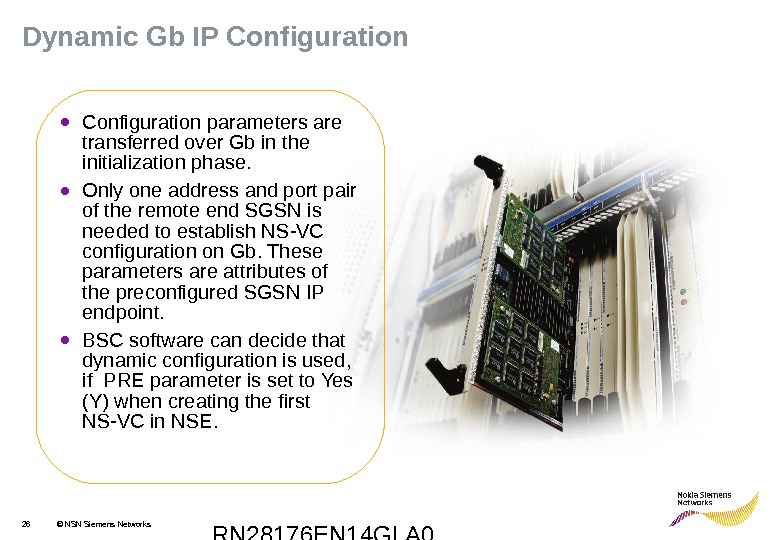
RN 28176 EN 14 GLA 026 © NSN Siemens Networks. Dynamic Gb IP Configuration • Configuration parameters are transferred over Gb in the initialization phase. • Only one address and port pair of the remote end SGSN is needed to establish NS-VC configuration on Gb. These parameters are attributes of the preconfigured SGSN IP endpoint. • BSC software can decide that dynamic configuration is used, if PRE parameter is set to Yes (Y) when creating the first NS-VC in NSE.
RN 28176 EN 14 GLA 027 © NSN Siemens Networks. Dynamic Gb IP Configuration PCU 4 (BCSU 2) NSEI: 13731 PSEI: 100 IP address: 10. 2. 77. 82 Port number: 33301 Remote IP address: 10. 2. 10. 15 Remote port number: 50001 PAPU 5 NSEI: 13731 PSEI: 100 IP address: 10. 2. 10. 15 Port numebr: 50001 Remote IP address: 10. 2. 77. 82 Remote port number: 33301 NS-VC 7301 PRE: YBSC 08 SGSN 01 RDW: 10 RSW:
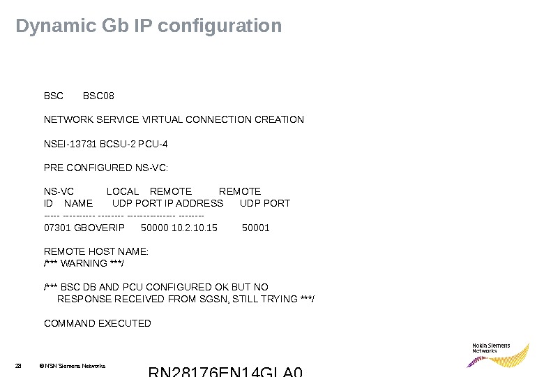
RN 28176 EN 14 GLA 028 © NSN Siemens Networks. Dynamic Gb IP configuration BSC 08 NETWORK SERVICE VIRTUAL CONNECTION CREATION NSEI-13731 BCSU-2 PCU-4 PRE CONFIGURED NS-VC: NS-VC LOCAL REMOTE ID NAME UDP PORT IP ADDRESS UDP PORT ———- —- 07301 GBOVERIP 50000 10. 2. 10. 15 50001 REMOTE HOST NAME: /*** WARNING ***/ /*** BSC DB AND PCU CONFIGURED OK BUT NO RESPONSE RECEIVED FROM SGSN, STILL TRYING ***/ COMMAND EXECUT
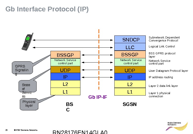
RN 28176 EN 14 GLA 029 © NSN Siemens Networks. Gb Interface Protocol (IP) SGSNBS C LLCSNDCP Gb IP-IF Subnetwork Dependent Convergence Protocol Logical Link Control BSS GPRS protocol layer Network Service control part State of Servic es. GPRS Signallin g UDPNetwork Service control part L 2 L 1 UDP IPNetwork Service control part L 2 L 1 BSSGP Physical layer Layer 1 physical connection. User Datagram Protocol layer Layer 2 data link layer IP address routing. BSSGP IP
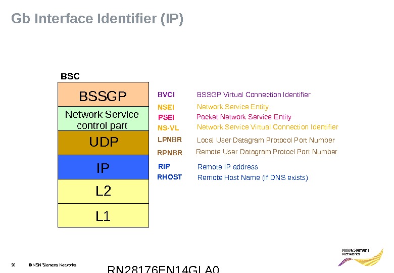
RN 28176 EN 14 GLA 030 © NSN Siemens Networks. Gb Interface Identifier (IP) BVCI LPNBRNSEI NS-V LBSSGP UDP L 2 Network Service control part. BSC BSSGP Virtual Connection Identifier Network Service Entity Network Service Virtual Connection Identifier Local User Datagram Protocol Port Number Remote User Datagram Protocl Port Number IP L 1 RPNBR RIP Remote IP address RHOST Remote Host Name (If DNS exists)PSEI Packet Network Service Entity
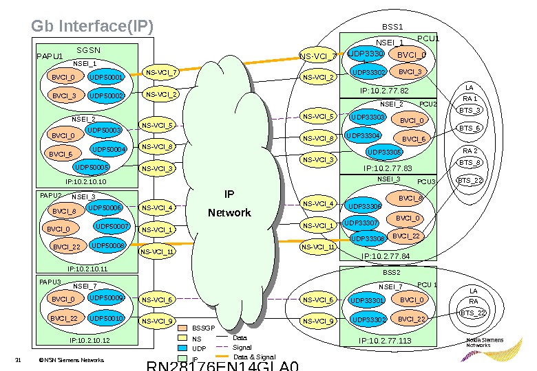
RN 28176 EN 14 GLA 031 © NSN Siemens Networks PCU 2 PCU 1 PCU 3 BTS_6 RA 1 BTS_8 BTS_22 RA 2 LA BTS_22 RA LANSEI_1 NSEI_2 NSEI_3 NSEI_7 PAPU 1 PAPU 2 PAPU 3 SGSN NSEI_7 NSEI_3 NSEI_1 NSEI_2 BVCI_3 BVCI_0 BVCI_6 BVCI_8 BVCI_0 BVCI_22 BVCI_0 BVCI_3 BVCI_0 UDP 50001 UDP 50002 UDP 50003 UDP 50004 UDP 50005 BVCI_0 BVCI_6 UDP 50007 UDP 50008 BVCI_8 BVCI_0 BVCI_22 BVCI_0 UDP 50009 UDP 50010 Data Signal Data & Signal BSS 2 BSS 1 UDP 33302 UDP 33303 UDP 33304 UDP 33305 UDP 33306 UDP 33307 UDP 33308 UDP 33301 UDP 33302 BSSGP NS IPUDP PCU 1 IP: 10. 2. 77. 82 IP: 10. 2. 77. 83 IP: 10. 2. 77. 84 IP: 10. 2. 77. 113 IP: 10. 2. 10. 11 IP: 10. 2. 10. 12 NS-VCI_7 NS-VCI_2 NS-VCI_5 NS-VCI_8 NS-VCI_3 NS-VCI_4 NS-VCI_11 NS-VCI_6 NS-VCI_9 IP Network Gb Interface(IP)
RN 28176 EN 14 GLA 032 © NSN Siemens Networks. Exercise: Read out Gb IF configuration (IP) NSEI______ PSEI_____ UDP_____PAPU______ NS-VCI_____ BCSU_____ PCU____ IP________ RPN______ LPN______ RDW______ RSW______ PRE ______ RIP_______Gateway IP_____SGSN_____ BSC_____ NSEI______ PSEI______ UDP_____ IP________RPN______ LPN______ RDW______ RSW______ PRE ______ RIP_______ SGSN BS
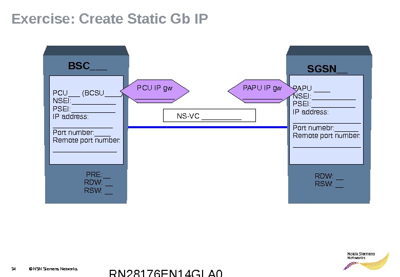
RN 28176 EN 14 GLA 033 © NSN Siemens Networks. Exercise: Create Static Gb IP NS-VC _____ PRE: __ RDW: __ RSW: __BSC___ SGSN__ RDW: __ RSW: __PCU___ (BCSU____) NSEI: ______ PSEI: ______ IP address: ________ Port number: ____ Remote port number: ________ PAPU ____ NSEI: ____ PSEI: ____ IP address: _________ Port numebr: ______ Remote port number: _________PCU IP gw _____ PAPU IP gw _____
RN 28176 EN 14 GLA 034 © NSN Siemens Networks. Exercise: Create Static Gb IP NS-VC _____ PRE: __ RDW: __ RSW: __BSC___ SGSN__ RDW: __ RSW: __PCU___ (BCSU____) NSEI: ______ PSEI: ______ IP address: ________ Port number: ____ Remote port number: ________ PAPU ____ NSEI: ______ PSEI: ______ IP address: _________ Port numebr: ______ Remote port number: _________PCU IP gw _____ PAPU IP gw _____
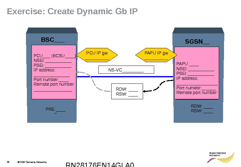
RN 28176 EN 14 GLA 035 © NSN Siemens Networks. Exercise: Create Dynamic Gb IP PCU___ (BCSU____) NSEI: ______ PSEI: ______ IP address: ________ Port number: ____ Remote port number: ________ PAPU ____ NSEI: ______ PSEI: ______ IP address: _________ Port numebr: ______ Remote port number: _________NS-VC_____ PRE: ____ _BSC___ SGSN__ RDW: ____ RSW: ____ PAPU IP gw _____PCU IP gw _____
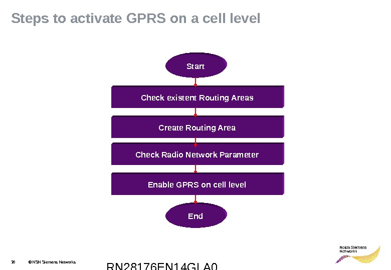
RN 28176 EN 14 GLA 036 © NSN Siemens Networks. Steps to activate GPRS on a cell level Check existent Routing Areas Create Routing Area Check Radio Network Parameter End. Start Enable GPRS on cell level
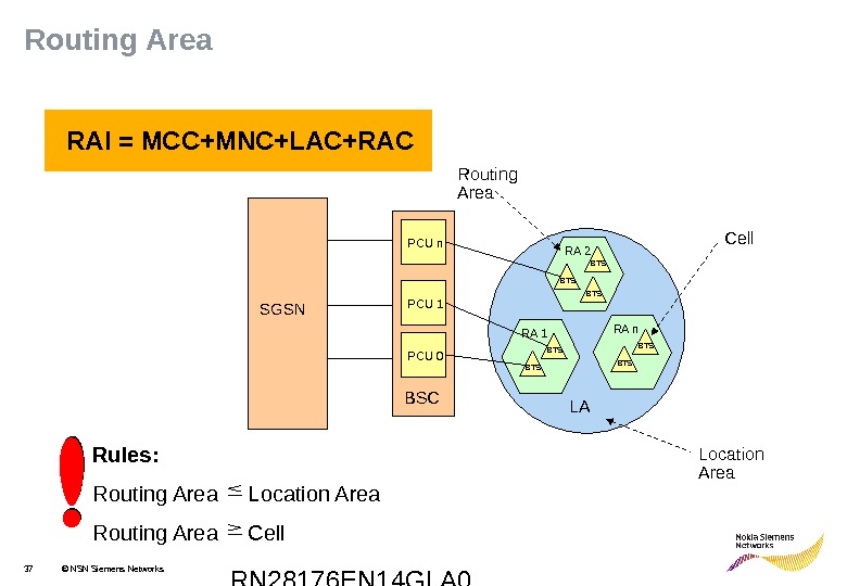
RN 28176 EN 14 GLA 037 © NSN Siemens Networks RAI = MCC+MNC+LAC+RAC Rules: Routing Area Location Area Routing Area Cell PCU 1 PCU 0 BTSRA 1 BTS RA 2 SGSN BTSRA n LA BTS BSC PCU n Location Area. Routing Area Cell. Routing Area
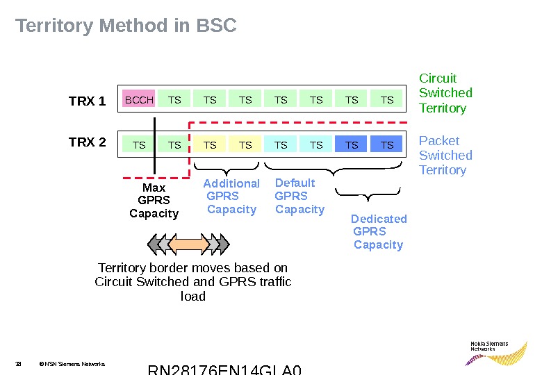
RN 28176 EN 14 GLA 038 © NSN Siemens Networks TRX 1 TRX 2 BCCH TS TS TS TSTS Circuit Switched Territory Packet Switched Territory border moves based on Circuit Switched and GPRS traffic load Default GPRS Capacity Dedicated GPRS Capacity. TS TS Additional GPRS Capacity. TS TS Max GPRS Capacity. Territory Method in BS
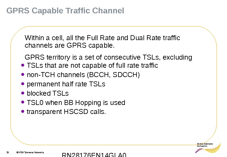
RN 28176 EN 14 GLA 039 © NSN Siemens Networks. GPRS Capable Traffic Channel Within a cell, all the Full Rate and Dual Rate traffic channels are GPRS capable. GPRS territory is a set of consecutive TSLs, excluding • TSLs that are not capable of full rate traffic • non-TCH channels (BCCH, SDCCH) • permanent half rate TSLs • blocked TSLs • TSL 0 when BB Hopping is used • transparent HSCSD calls.
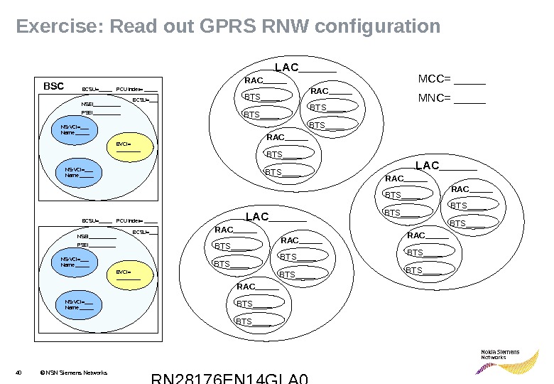
RN 28176 EN 14 GLA 040 © NSN Siemens Networks BCSU=___ NS-VCI=___ Name _____ NSEI_____ PSEI_____ NS-VCI=___ Name _____BSC NS-VCI=___ Name _____ BCSU=___ NSEI_____ PSEI_____ RAC_____ BTS____ RAC_____ BTS____ LAC______BVCI= _________ RAC_____ BTS____ BTS____ RAC_____ BTS____ LAC______ MCC= _____ MNC= _____BCSU=_____ PCU index= _____Exercise: Read out GPRS RNW configuration
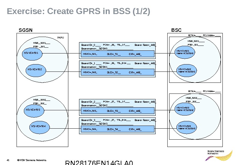
RN 28176 EN 14 GLA 041 © NSN Siemens Networks. Exercise : Create GPRS in BSS (1/2) Bearername=__SGSN 1__________Bearer. ID=_1 ____ PCM= _36_ TSL_8 -14 ___ Bearer Rate=_448_ NSVCI=_502_ DLCI=_52__ CIR=_448_ Bearername=__________________________Bearer. ID=______ PCM= ____ TSL________ Bearer Rate=_____ NSVCI=____ _ DLCI=_____ CIR=_____Bearername=__SGSN 0__________Bearer. ID=_0____ PCM= _36_ TSL_1 -7____ Bearer Rate=_448_ NSVCI=_501_ DLCI=_51__ CIR=_448_PAPU NS-VCI=___ NS-VC=___SGSN NS-VCI=501 Name VCSGSN 0 NSEI_5001_____ PSEI _501_____ NS-VCI=___ Name _____BSC NS-VCI=___ Name _____ NSEI_5002____ PSEI _502___NSEI__5001____ PSEI __501___ NSEI__5002____ PSEI__502__ NS-VCI=502 Name VCSGSN 1 NS-VCI=503 Name VCSGSN 2 NS-VCI=504 Name VCSGSN 3 NS-VCI=504 NS-VCI=503 NS-VCI=502 NS-VCI=501 Bearername=__SGSN 2__________Bearer. ID=_2____ PCM= _37_ TSL_1 -7____ Bearer Rate=_448_ NSVCI=_503_ DLCI=_53__ CIR=_448_ Bearername=__SGSN 3__________Bearer. ID=_3____ PCM= _37_ TSL_8 -14____ Bearer Rate=_448_ NSVCI=_504_ DLCI=_54__ CIR=_448_ BCSU=_____ PCU index= _____
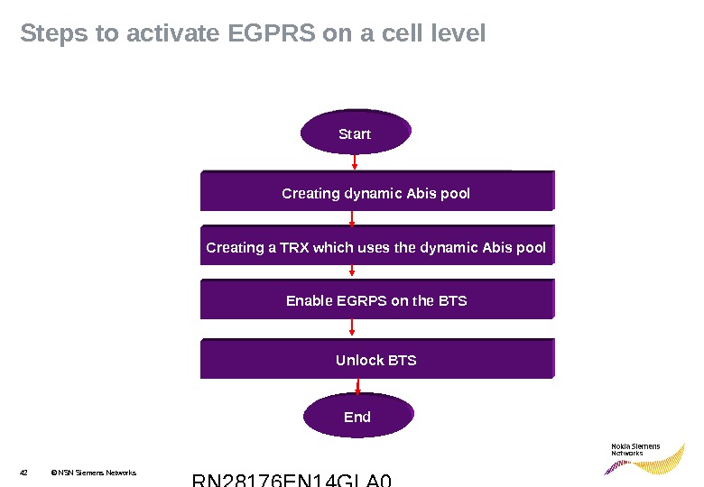
RN 28176 EN 14 GLA 042 © NSN Siemens Networks. Steps to activate EGPRS on a cell level Creating dynamic Abis pool Creating a TRX which uses the dynamic Abis pool End. Start Enable EGRPS on the BTS Unlock BTSCreating dynamic Abis pool Start
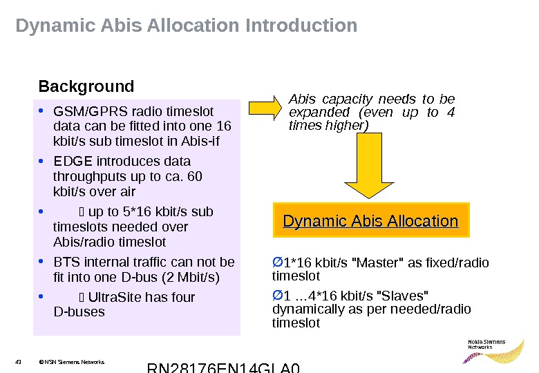
RN 28176 EN 14 GLA 043 © NSN Siemens Networks. Dynamic Abis Allocation Introduction • GSM/GPRS radio timeslot data can be fitted into one 16 kbit/s sub timeslot in Abis-if • EDGE introduces data throughputs up to ca. 60 kbit/s over air • up to 5*16 kbit/s sub timeslots needed over Abis/radio timeslot • BTS internal traffic can not be fit into one D-bus (2 Mbit/s) • Ultra. Site has four D-buses Abis capacity needs to be expanded (even up to 4 times higher) Dynamic Abis Allocation Ø 1*16 kbit/s «Master» as fixed/radio timeslot Ø 1 … 4*16 kbit/s «Slaves» dynamically as per needed/radio timeslot. Background
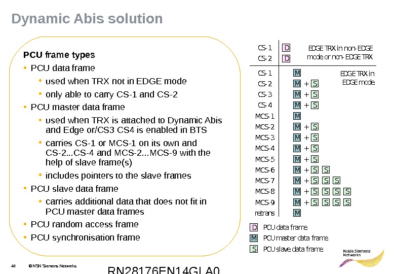
RN 28176 EN 14 GLA 044 © NSN Siemens Networks. PCU frame types • PCU data frame • used when TRX not in EDGE mode • only able to carry CS-1 and CS-2 • PCU master data frame • used when TRX is attached to Dynamic Abis and Edge or/CS 3 CS 4 is enabled in BTS • carries CS-1 or MCS-1 on its own and CS-2. . . CS-4 and MCS-2. . . MCS-9 with the help of slave frame(s) • includes pointers to the slave frames • PCU slave data frame • carries additional data that does not fit in PCU master data frames • PCU random access frame • PCU synchronisation frame. MCS- 1 M M M M M S S S CS- 4 CS- 3 CS- 2 CS- 1 MCS- 2 MCS- 3 MCS- 4 MCS- 5 MCS- 6 MCS- 7 MCS- 8 MCS- 9 S S S S S M M S S S S CS- 2 CS- 1 D DEDGE TRX in non-EDGE mode or non- EDGE TRX in EDGE mode D M S PCU data frame PCU master data frame PCU slave data frame + + + retrans. MDynamic Abis solution
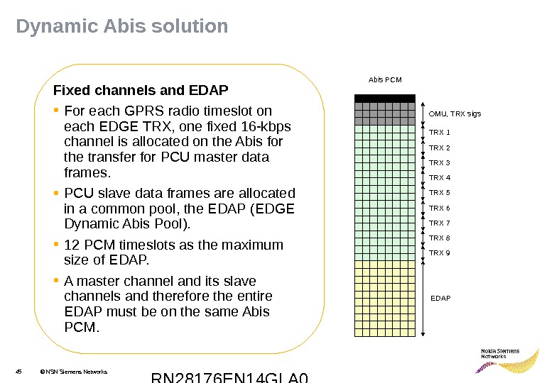
RN 28176 EN 14 GLA 045 © NSN Siemens Networks Fixed channels and EDAP • For each GPRS radio timeslot on each EDGE TRX, one fixed 16 -kbps channel is allocated on the Abis for the transfer for PCU master data frames. • PCU slave data frames are allocated in a common pool, the EDAP (EDGE Dynamic Abis Pool). • 12 PCM timeslots as the maximum size of EDAP. • A master channel and its slave channels and therefore the entire EDAP must be on the same Abis PCM TRX 1 TRX 2 TRX 3 OMU, TRX sigs EDAPTRX 4 TRX 5 TRX 6 TRX 7 TRX 8 TRX 9 Dynamic Abis solution
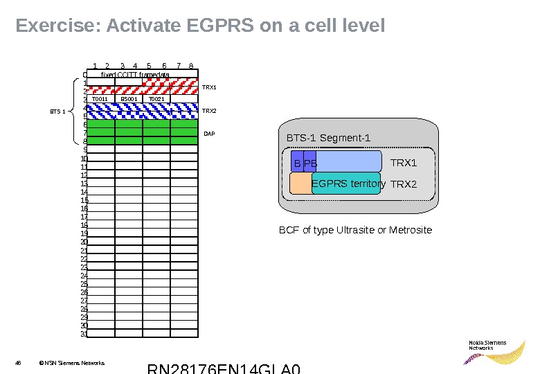
RN 28176 EN 14 GLA 046 © NSN Siemens Networks. Exercise: A ctivate EGPRS on a cell level B Segment-1 BTS-1 BCF of type Ultrasite or Metrosite EGPRS territory. PB TRX 1 TRX 2 f i x e d C C I T T f r a m e d a t a 1 2 4 5 6 7 83 0 1 2 3 4 5 6 7 8 9 1 0 1 1 1 2 1 3 1 4 15 1 6 1 7 1 8 2 0 2 2 2 6 2 9 3 11 9 2 1 2 3 2 4 2 5 2 7 2 8 3 0 T 0011 BS 001 T 0021 TRX 2 BTS 1 DAP
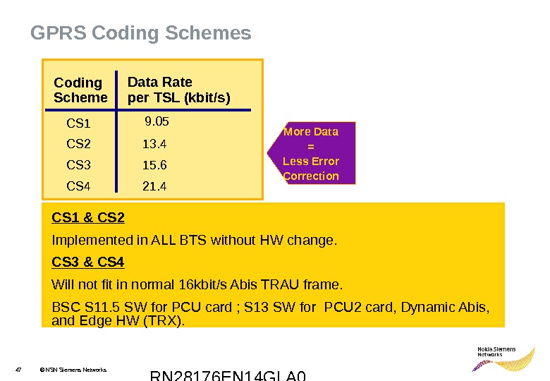
RN 28176 EN 14 GLA 047 © NSN Siemens Networks. GPRS Coding Schemes CS 1 & CS 2 Implemented in ALL BTS without HW change. CS 3 & CS 4 Will not fit in normal 16 kbit/s Abis TRAU frame. BSC S 11. 5 SW for PCU card ; S 13 SW for PCU 2 card, Dynamic Abis, and Edge HW (TRX). Coding Scheme CS 1 CS 2 CS 3 CS 4 Data Rate per TSL (kbit/s) 9. 05 13. 4 15. 6 21. 4 More Data = Less Error Correction
RN 28176 EN 14 GLA 048 © NSN Siemens Networks. Functional Description • When CS 3 -CS 4 option is on, and the Dynamic Abis pool and (E)GPRS territories are created then all GPRS coding schemes (CS 1 -CS 4) are available for data transfer. • The current GPRS Link Adaptation algorithm in the PCU/RLC is replaced with a new one, which covers also CS 3 and CS 4. • A data block of CS 2 -CS 4 is transferred in one PCU master Data Frame and one PCU Slave Data Frame through the Abis interface. CS 1 data block fits in one PCU Master Data Frame.