
Reservoir Simulation Gridding and Well Modelling Sergey Kurelenkov


4_-_gridding_and_well_modelling.ppt
- Размер: 4.3 Mегабайта
- Количество слайдов: 81
Описание презентации Reservoir Simulation Gridding and Well Modelling Sergey Kurelenkov по слайдам
Reservoir Simulation Gridding and Well Modelling Sergey Kurelenkov 2011 (after Ken Sorbie)
Outline • Gridding in Reservoir Simulation • Calculation of Block to Block Flows in Reservoir Simulators • Wells in Reservoir Simulation
Gridding in Reservoir Simulation • Reservoir Simulation Model – grid block model of a petroleum reservoir… • Gridding – process of dividing up a reservoir into grid blocks ( spatial discretization ) • Discretization – process of dividing up a continuous quantity into discrete intervals
Gridding in Reservoir Simulation Discretization Spatial Temporal t. Q Δ t (timestep)Δ x, Δ y, Δ z φ , k, c, S, p PVT
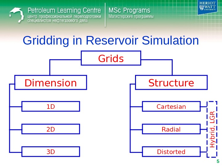
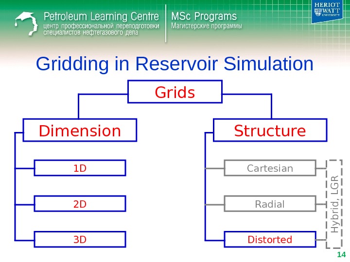
Gridding in Reservoir Simulation Grids Dimension Structure 1 D 2 D 3 D Cartesian Radial Distorted. H y b rid , L G R
Gridding in Reservoir Simulation Grids Dimension Structure 1 D 2 D 3 D Cartesian Radial Distorted. H y b rid , L G R
Gridding in Reservoir Simulation • 1 D Cartesian (Linear) Grids – Horizontal • Buckley-Leverett type water displacement – Vertical • gravity drainage • gravity stable gas displacement of oil x. S w Q w. Q o Q g
Gridding in Reservoir Simulation • 2 D Cartesian Grids – Cross-sectional (x/z) • vertical sweep efficiency • water/oil displacements in geostatistically generated cross-section • generation of pseudo-relative permeabilities (2 phase upscaling) • mechanism of gas displacement (importance of gravity)
Gridding in Reservoir Simulation • 2 D Cartesian Grids – Areal (x/y) • areal sweep efficiency (water/gas flooding) • benefits of infill drilling in an areal pattern flood • near-miscible gas injection in a homogeneous layer
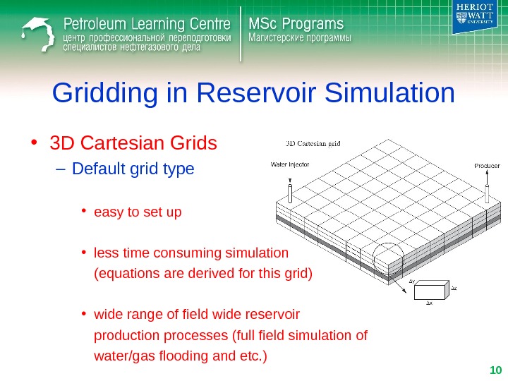
Gridding in Reservoir Simulation • 3 D Cartesian Grids – Default grid type • easy to set up • less time consuming simulation (equations are derived for this grid) • wide range of field wide reservoir production processes (full field simulation of water/gas flooding and etc. )
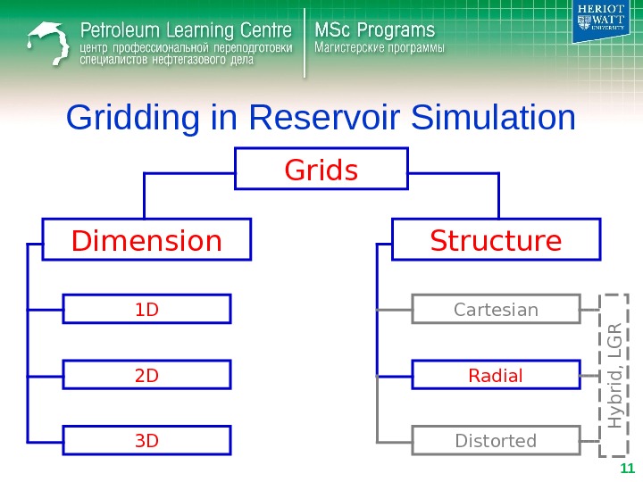
Gridding in Reservoir Simulation Grids Dimension Structure 1 D 2 D 3 D Cartesian Radial Distorted. H y b rid , L G R
Gridding in Reservoir Simulation • Radial Grids – 1 D • pressure front propagation – 2 D (r/z), 3 D • near wellbore processes (water/gas coning)
Gridding in Reservoir Simulation • Radial Grids – pressure change near well is steep – logarithmically-spaced grid • grid is divided such that wr r r. Pln~)( const)()(1 iir. P 1 iiirrr const 1 i i r r 1 1 ln~)()( i i ii r r r. P
Gridding in Reservoir Simulation Grids Dimension Structure 1 D 2 D 3 D Cartesian Radial Distorted. H y b rid , L G R
Gridding in Reservoir Simulation • Distorted grids – Corner Point • account structure features (faults) 8 corners
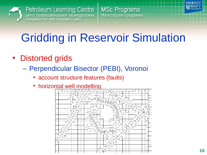
Gridding in Reservoir Simulation • Distorted grids – Perpendicular Bisector (PEBI), Voronoi • account structure features (faults) • horizontal well modelling
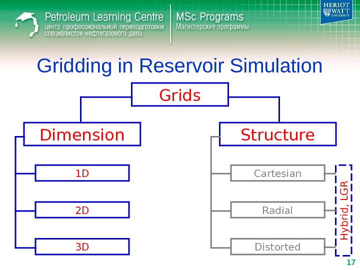
Gridding in Reservoir Simulation Grids Dimension Structure 1 D 2 D 3 D Cartesian Radial Distorted. H y b rid , L G R
Gridding in Reservoir Simulation • Local Grid Refinement (LGR) – Simple grid refinement Refinement in area of interest Refinement where not required (e. g. aquifer)
Gridding in Reservoir Simulation • Local Grid Refinement (LGR) – Local Grid Refinement in area of interest Keep coarse grid where not required (e. g. aquifer)
Gridding in Reservoir Simulation • Local Grid Refinement (LGR) – Hybrid Grid Local Grid Refinement
Gridding in Reservoir Simulation • Local Grid Refinement (LGR) – Hybrid Grid Local Grid Refinement
Gridding in Reservoir Simulation • Distorted grids – Faults modelling • Non-neighbor connections (NNC)
Gridding in Reservoir Simulation Numerical problems Numerical dispersion Grid orientation
Gridding in Reservoir Simulation Numerical problems Numerical dispersion Grid orientation
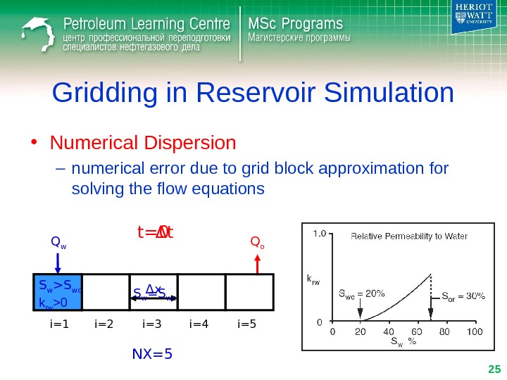
Gridding in Reservoir Simulation • Numerical Dispersion – numerical error due to grid block approximation for solving the flow equations Q w Q o i=1 i=2 i=3 i=4 i=5Δ x S w =S wct= Δ t 0 NX=5 S w >S wc k rw >
Gridding in Reservoir Simulation • Numerical Dispersion – numerical error due to grid block approximation for solving the flow equations Q w Q o i=1 i=2 i=3 i=4 i=5 t= 2 Δ t NX=5 S w >S wc k rw >
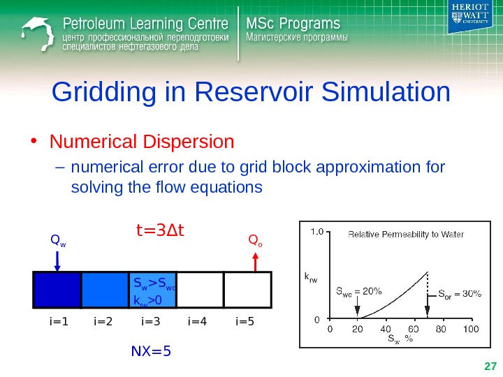
Gridding in Reservoir Simulation • Numerical Dispersion – numerical error due to grid block approximation for solving the flow equations Q w Q o i=1 i=2 i=3 i=4 i=5 t= 3 Δ t NX=5 S w >S wc k rw >
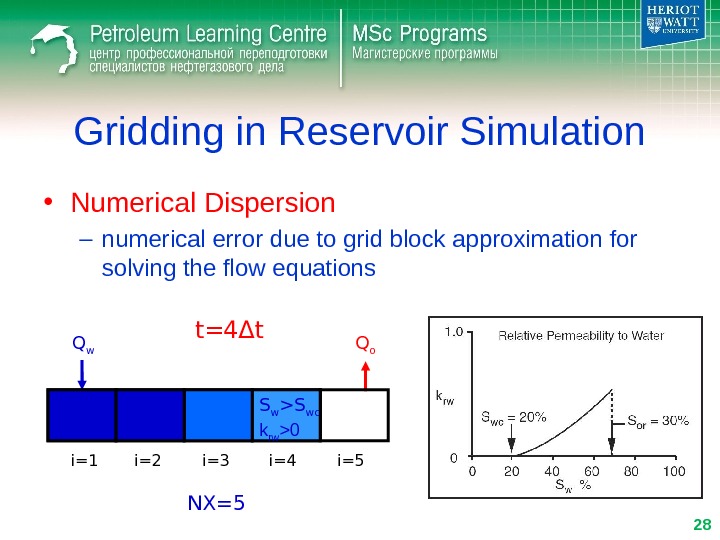
Gridding in Reservoir Simulation • Numerical Dispersion – numerical error due to grid block approximation for solving the flow equations Q w Q o i=1 i=2 i=3 i=4 i=5 t= 4 Δ t NX=5 S w >S wc k rw >
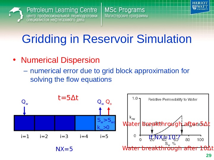
Gridding in Reservoir Simulation • Numerical Dispersion – numerical error due to grid block approximation for solving the flow equations Q w Q o i=1 i=2 i=3 i=4 i=5 t= 5 Δ t NX=5 S w >S wc k rw >0 Q w Water breakthrough after 5 Δ t If NX=10 ? Water breakthrough after 10 Δ t’
Gridding in Reservoir Simulation • Numerical Dispersion – saturation front spreading Analytical solution (Buckley-Levere tt) Numerical solution
Gridding in Reservoir Simulation • Numerical Dispersion – Methods of reducing • Grid refinement (increase in number of grid blocks) • Use of Pseudo-relative permeabilities (2 phase upscaling) • Use of alternative simulation scheme (Streamline simulation) S wcr
Gridding in Reservoir Simulation Numerical problems Numerical dispersion Grid orientation
Gridding in Reservoir Simulation • Grid Orientation effect – arises when the fluid flow both oriented with the principal and diagonal grid direction L L P 1 P
Gridding in Reservoir Simulation • Grid Orientation effect – Methods of reducing • Grid refinement (increase in number of grid blocks) • Use of distorted grids (PEBI) • Use of improved numerical schemes (9 -point) • Use of alternative simulation scheme (Streamline simulation) 5 -point 9 -point
Gridding in Reservoir Simulation • Streamline Simulation Pressure Streamlines Saturation
Gridding in Reservoir Simulation • Issues in Choosing Reservoir Simulation Grid – Grid Dimension • 1 D, 2 D, 3 D ? – Grid Geometry/Structure • Cartesian, Distorted, LGR ? – Grid Fineness/Coarseness • Grid block size (number of grid blocks) ? should be related to the simplicity/complexity of the problem
Gridding in Reservoir Simulation • Issues in Choosing Reservoir Simulation Grid – Example
• Issues in Choosing Reservoir Simulation Grid – Example 1 Gridding in Reservoir Simulation
Gridding in Reservoir Simulation • Issues in Choosing Reservoir Simulation Grid – Example 1 MWAG Waterflooding
• Issues in Choosing Reservoir Simulation Grid – Example 2 Gridding in Reservoir Simulation
Outline • Gridding in Reservoir Simulation • Calculation of Block to Block Flows in Reservoir Simulators • Wells in Reservoir Simulation
Calculation of Block to Block Flows in Reservoir Simulators • Darcy Law for Inter Block Flow x P B k AQ p p p x P i-1 ? 2 1 1 ii ii p p xx PP B k
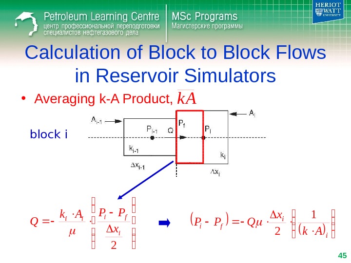
Calculation of Block to Block Flows in Reservoir Simulators • Averaging k-A Product, k A 2 1 1 ii ii p p p xx PP B k AQ
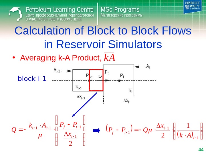
Calculation of Block to Block Flows in Reservoir Simulators • Averaging k-A Product, 2 1 111 i ifii x PPAk Q 1 1 2 i i if Ak x QPP block i-1 44 k
Calculation of Block to Block Flows in Reservoir Simulators • Averaging k-A Product, 2 i fiii x PPAk Q i i fi Ak x QPP 1 2 block i 45 k
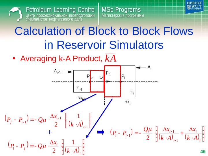
i i ii Ak x. Q PP 1 1 1 2 Calculation of Block to Block Flows in Reservoir Simulators • Averaging k-A Product, 1 1 2 i i if Ak x QPP i i fi Ak x QPP 1 2 + 46 k
i i ii Ak x. Q PP 1 1 1 2 Calculation of Block to Block Flows in Reservoir Simulators • Averaging k-A Product, 1 1 1 21 ii i i PP Ak x Q 47 k
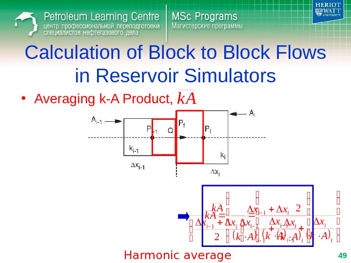
2 1 1 ii ii xx PPk A Q Calculation of Block to Block Flows in Reservoir Simulators • Averaging k-A Product, 1 1 1 21 ii i i PP Ak x Q i iii Ak xxx k A 1 11 2 2 48 k
Calculation of Block to Block Flows in Reservoir Simulators • Averaging k-A Product, i iii Ak xxx k A 1 11 2 2 i i ii Ak x xx k A 1 1 1 Harmonic average 49 k
Calculation of Block to Block Flows in Reservoir Simulators • Averaging k-A Product, 2 1 1 ii ii p p p xx PP B k AQ Harmonic average 50 k
Calculation of Block to Block Flows in Reservoir Simulators • Averaging Two-Phase Mobility, p 2 1 1 ii ii p p p xx PP B k AQ p rp p k 2 1 1 ii ii pp rp xx PP B k k A 2 1 ii p BB B Arithmetic average
Calculation of Block to Block Flows in Reservoir Simulators • Averaging Two-Phase Mobility, 2 1 1 ii ii pp rp p xx PP B k k AQ Harmonic average Arithmetic average 52 p
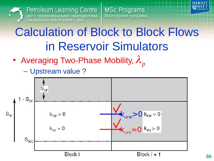
Calculation of Block to Block Flows in Reservoir Simulators • Averaging Two-Phase Mobility, – Physically Q w >0 Q o =0 53 p
• Averaging Two-Phase Mobility, – Harmonic average (kh ) ? Calculation of Block to Block Flows in Reservoir Simulators k hrw =0 k hro =0 54 p
• Averaging Two-Phase Mobility, – Arithmetic average (ka ) ? Calculation of Block to Block Flows in Reservoir Simulators k arw >0 k aro >0 55 p
• Averaging Two-Phase Mobility, – Upstream value ? Calculation of Block to Block Flows in Reservoir Simulators k urw >0 k uro =0 56 p
• Averaging Two-Phase Mobility, – Upstream value ? Calculation of Block to Block Flows in Reservoir Simulators k urw =0 k uro >0 57 p
Calculation of Block to Block Flows in Reservoir Simulators • Summary x P B k k AQ pp rp p Harmonic average Arithmetic average Upstream value P i-
Outline • Gridding in Reservoir Simulation • Calculation of Block to Block Flows in Reservoir Simulators • Wells in Reservoir Simulation
• Basic Idea of Well Model Wells in Reservoir Simulation Δ P f->w ( Δ P skin )Δ P well Δ P f->sΔ P s P wh P wf
Wells in Reservoir Simulation • Well Models for Single and Two Phase Flow)(wfe. PPPIQ Givens Controls P wf Q P wf. Q or Limits
Wells in Reservoir Simulation • Well Models for Single and Two Phase Flow)(wfe. PPPIQ wr r k h Q r. Pln 2 )( ln 2 wfe w e PP r r k h Q P=P e at r e : w e wfe r r k h Q PPln
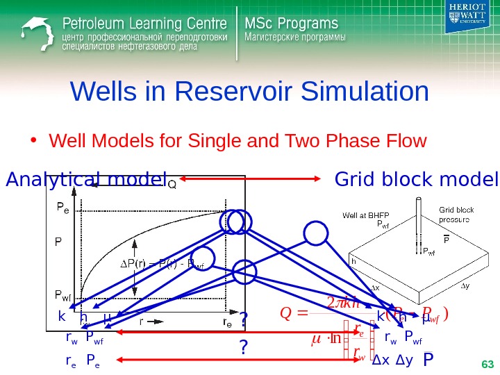
Wells in Reservoir Simulation • Well Models for Single and Two Phase Flow)( ln 2 wfe w e PP r r k h Q Analytical model Grid block model k h μ r er w P wf P e k h μ r w P wf Δ x Δ y P? ?
Wells in Reservoir Simulation • Well Models for Single and Two Phase Flow)( ln 2 wfe w e PP r r k h Q Analytical model Grid block model r e P e Δ x Δ y P = ? P r e
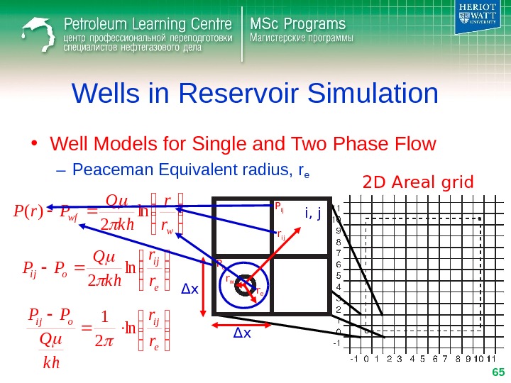
Wells in Reservoir Simulation • Well Models for Single and Two Phase Flow – Peaceman Equivalent radius, re 2 D Areal grid r er w r ij i, j P 0 P ij Δ xΔ x w wf r r k h Q Pr. Pln 2 )( e ij oij r r k h Q PPln 2 e ijoij r r k h Q PP ln
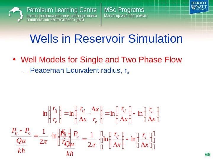
Wells in Reservoir Simulation • Well Models for Single and Two Phase Flow – Peaceman Equivalent radius, re e ijoij r r k h Q PP ln 2 1 x r r x x r r reij e ij lnln x r k h Q PPeijoi j lnln
Wells in Reservoir Simulation • Well Models for Single and Two Phase Flow – Peaceman Equivalent radius, re x r k h Q PPeijoi j lnln 2 1 y = k · ( x – a ) r ij / Δ x 0. 2 x reΔxre 0.
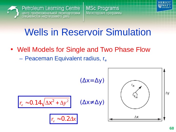
Wells in Reservoir Simulation • Well Models for Single and Two Phase Flow – Peaceman Equivalent radius, re Δxre 0. 2 ( Δ x= Δ y) 2 yre 2 x 0. 14 ( Δ x≠ Δ y)
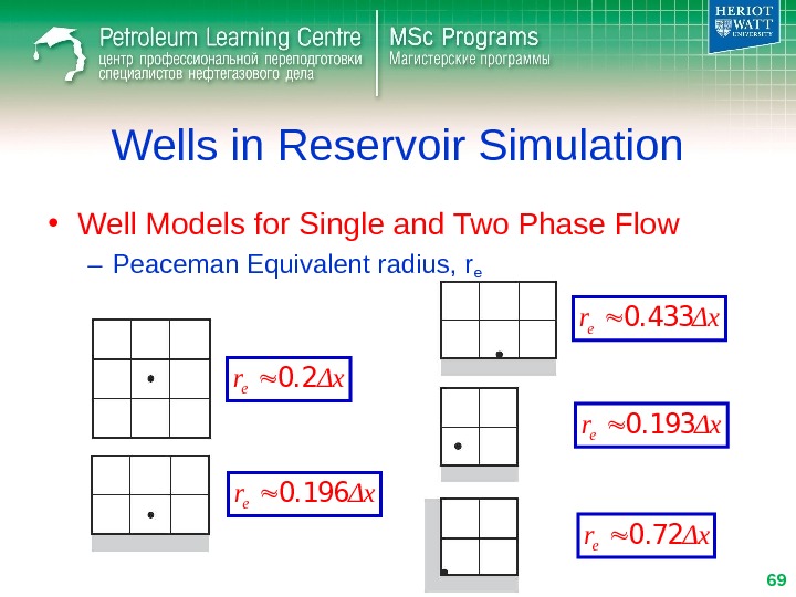
Wells in Reservoir Simulation • Well Models for Single and Two Phase Flow – Peaceman Equivalent radius, re Δxre 0. 196 Δxre 0. 2 Δxre 0. 433 Δxre 0. 193 Δxre 0.
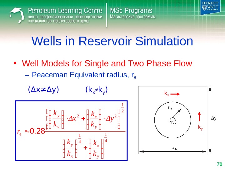
Wells in Reservoir Simulation • Well Models for Single and Two Phase Flow – Peaceman Equivalent radius, re (k x ≠ k y ) 4 1 2 1 22 y x x y e k k Δy k k Δx k k r 0. 28( Δ x≠ Δ y) k x k y
Wells in Reservoir Simulation • Well Models for Single and Two Phase Flow)( ln 2 wfe w e PP r r k h Q Analytical model Grid block model r e Δ x Δ y = ? P r e P e P 22ΔyΔx 0. 14 =
Wells in Reservoir Simulation • Well Models for Single and Two Phase Flow – Two phase flow. P )(wfoo. PPPIQ)(wfww. PPPIQ w e o oro o r r Skk h PI ln )(2 w e w wrw w r r Skk h PI ln )(
Wells in Reservoir Simulation • Well Modelling in a Multi-Layer System
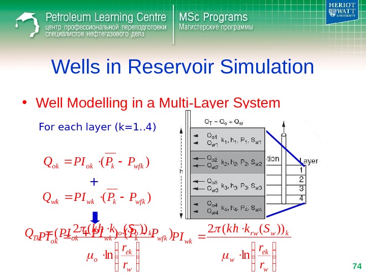
Wells in Reservoir Simulation • Well Modelling in a Multi-Layer System For each layer (k=1. . 4))(wfkkokok. PPPIQ w ek o koro ok r r Skk h PI ln ))((2 )(wf kkwkwk. PPPIQ w ek w kwrw wk r r Skk h PI ln ))((2 +)()(wfkkwkok. Tk. PPPIPIQ
Wells in Reservoir Simulation • Well Modelling in a Multi-Layer System For each layer (k=1. . 4))(wfkkokok. PPPIQ )(wf kkwkwk. PPPIQ )()(wfkkwkok. Tk. PPPIPIQ 4 1 )()( k wfkkwkok. TPPPIPIQ Total 4 1 )( k wfkkoko. PPPIQ 4 1 )( k wfkkwkw. PPPIQ For simplicity 4321 wfwf. PPPP
Wells in Reservoir Simulation • Modelling Horizontal Wells)(, , , , kjwfikjikjoi. PPPIQ i, j, k
Wells in Reservoir Simulation • Modelling Horizontal Wells
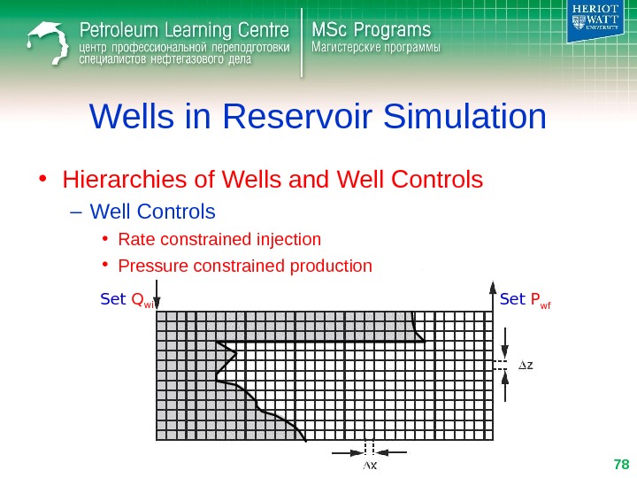
Wells in Reservoir Simulation • Hierarchies of Wells and Well Controls – Well Controls • Rate constrained injection • Pressure constrained production Set Q wi Set P wf
Wells in Reservoir Simulation • Hierarchies of Wells and Well Controls – Well Controls • Rate or Pressure constrained production • Voidage replacement (injection) variable Q wi Q op + Q wp Q wi res =Q wi ·B w Q p res =Q op ·B o +Q wp ·B w
Wells in Reservoir Simulation • Hierarchies of Wells and Well Controls – Well Controls • Rate or Pressure constrained production • Voidage replacement (injection) variable Q wi Q op + Q wp Q wi res =Q wi ·B w Q p res =Q op ·B o +Q wp ·B w. Q wi ·B w =Q op ·B o +Q wp ·B w. Q wi =Q op ·(B o /B w ) +Q wp
Thank you for attention! Reservoir Simulation Gridding and Well Modelling Sergey Kurelenkov