
RBEs and MPCs in MSC. Nastran ARipRoarin’Reviewof RigidElements


rbe_and_mpc_in_nastran.ppt
- Размер: 1.8 Mегабайта
- Количество слайдов: 94
Описание презентации RBEs and MPCs in MSC. Nastran ARipRoarin’Reviewof RigidElements по слайдам
RBEs and MPCs in MSC. Nastran ARip. Roarin’Reviewof Rigid. Elements
Slide 2 RBEs and MPCs • Notnecessarily“rigid”elements – Working. Definition: Themotionofa. DOFisdependenton the motion ofatleastoneother. DO
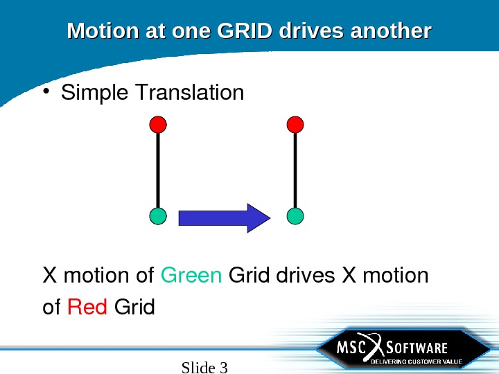
Slide 3 Motion at one GRID drives another • Simple. Translation Xmotionof Green Griddrives. Xmotion of Red Grid
Slide 4 Motion at one GRID drives another • Simple. Rotationof Green Griddrives. Xtranslation and. Zrotationof Red Grid
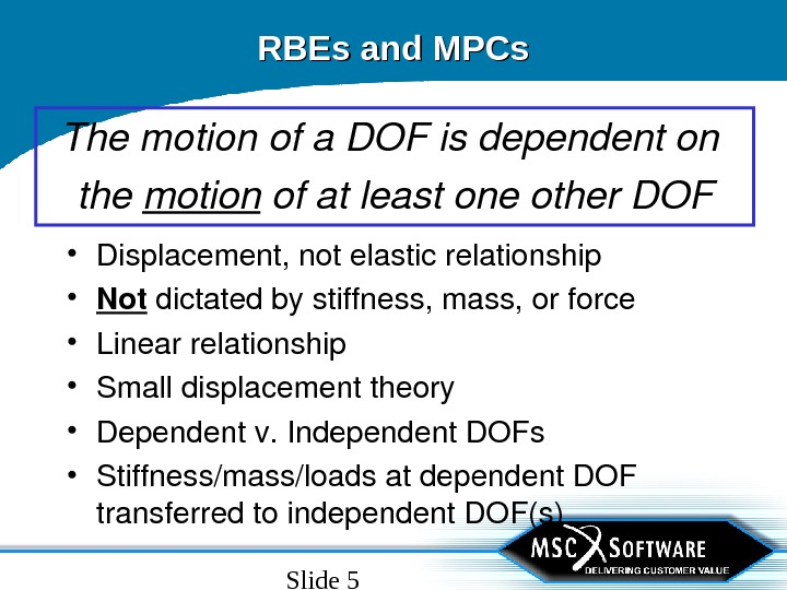
Slide 5 RBEs and MPCs Themotionofa. DOFisdependenton the motion ofatleastoneother. DOF • Displacement, notelasticrelationship • Not dictatedbystiffness, mass, orforce • Linearrelationship • Smalldisplacementtheory • Dependentv. Independent. DOFs • Stiffness/mass/loadsatdependent. DOF transferredtoindependent. DOF(s)
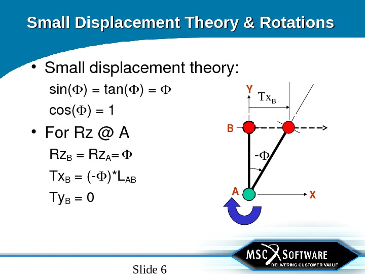
Slide 6 Small Displacement Theory & Rotations • Smalldisplacementtheory: sin( )=tan( )= cos( )=1 • For. Rz@A Rz. B =Rz. A = Tx B =( )*LAB Ty B =0 XY AB Tx
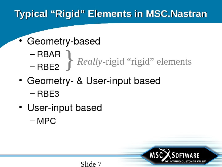
Slide 7 • Geometrybased – RBAR – RBE 2 • Geometry&Userinputbased – RBE 3 • Userinputbased – MPCTypical “Rigid” Elements in MSC. Nastran } Really- rigid “rigid” elements
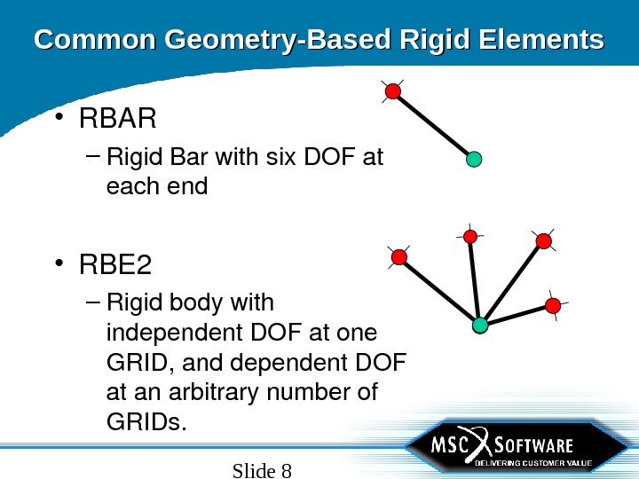
Slide 8 Common Geometry-Based Rigid Elements • RBAR – Rigid. Barwithsix. DOFat eachend • RBE 2 – Rigidbodywith independent. DOFatone GRID, anddependent. DOF atanarbitrarynumberof GRIDs.
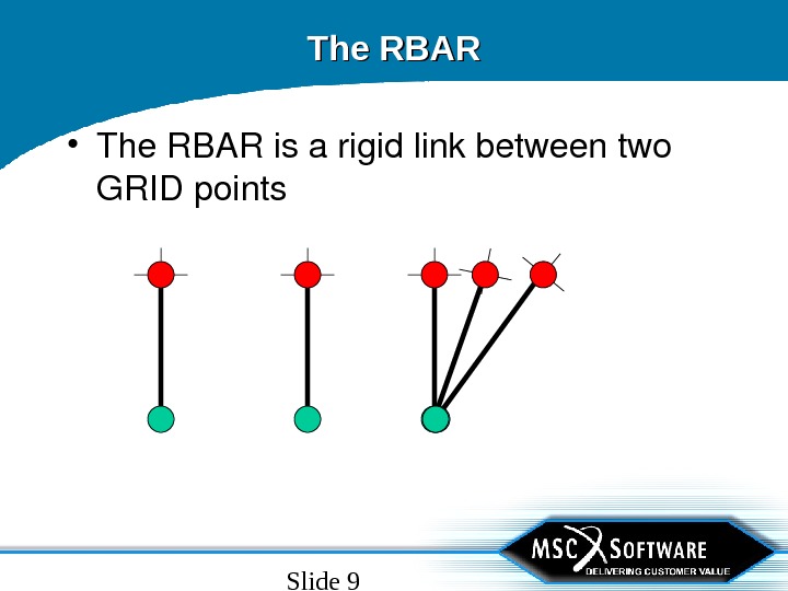
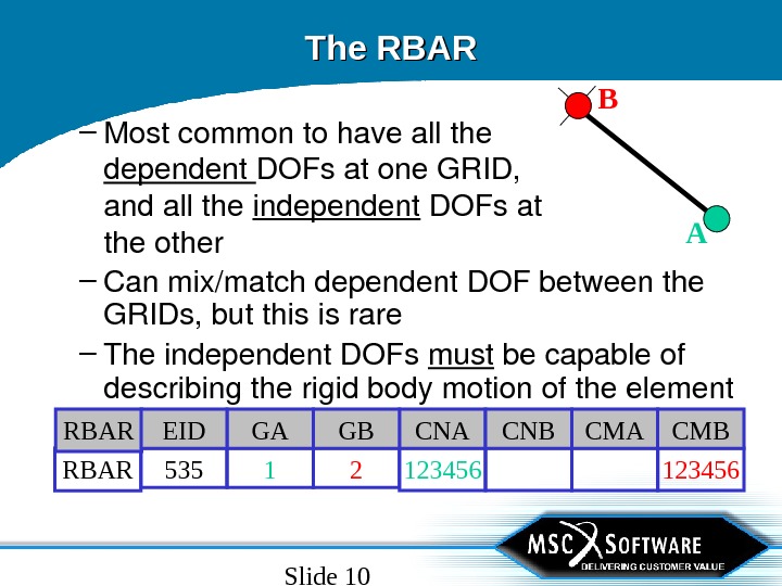
Slide 9 The RBAR • The. RBARisarigidlinkbetweentwo GRIDpoints
Slide 10 The RBAR – Canmix/matchdependent. DOFbetweenthe GRIDs, butthisisrare – Theindependent. DOFs must becapableof describingtherigidbodymotionoftheelement 1234561 2 RBAR 535 CMA CMBCNA CNBGA GBRBAR EID– Mostcommontohaveallthe dependent DOFsatone. GRID, andallthe independent DOFsat theother
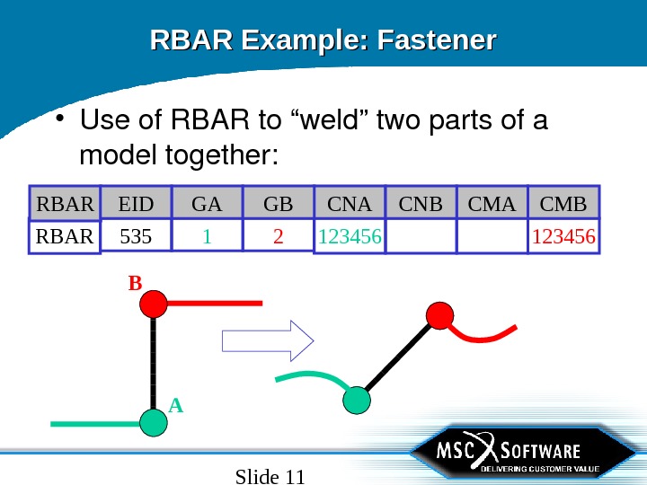
Slide 11 RBAR Example: Fastener • Useof. RBARto“weld”twopartsofa modeltogether: 1234561 2 RBAR 535 CMA CMBCNA CNBGA GBRBAR EI
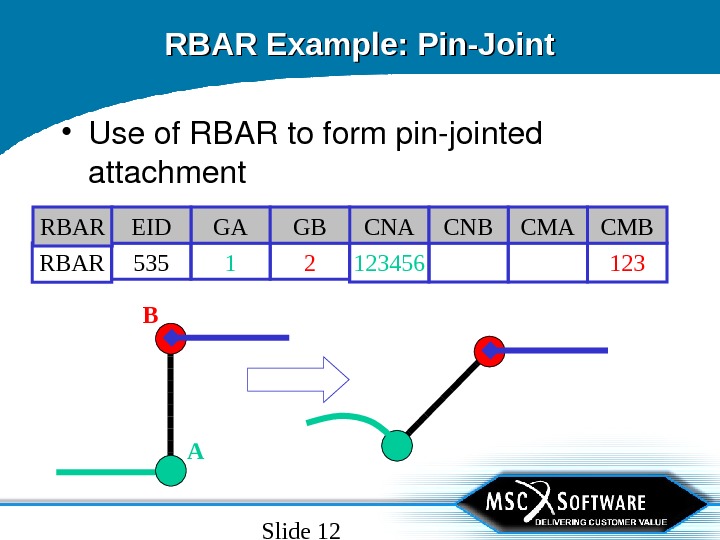
Slide 12 RBAR Example: Pin-Joint • Useof. RBARtoformpinjointed attachment 1231234561 2 RBAR 535 CMA CMBCNA CNBGA GBRBAR EI
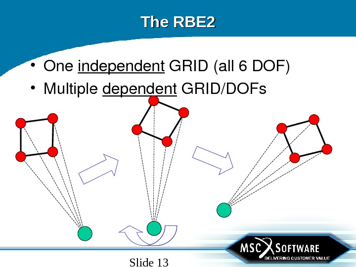
Slide 13 The RBE 2 • One independent GRID(all 6 DOF) • Multiple dependent GRID/DOFs
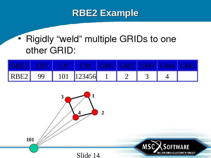
Slide 14 RBE 2 Example • Rigidly“weld”multiple. GRIDstoone other. GRID: 32 RBE 2 4110199 123456 GM 5 GM 3 GM 2 RBE 2 GM 4 GM 1 GNEID CM
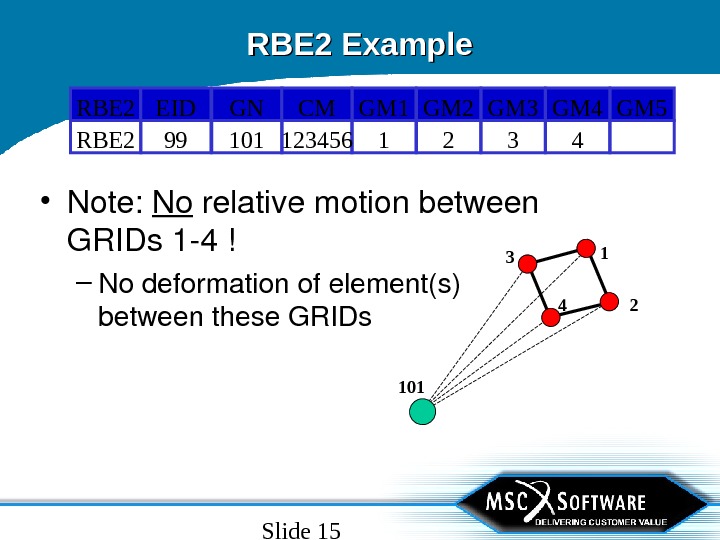
Slide 15 RBE 2 Example • Note: No relativemotionbetween GRIDs 14! – Nodeformationofelement(s) betweenthese. GRIDs 32 RBE 2 4110199 123456 GM 5 GM 3 GM 2 RBE 2 GM 4 GM 1 GNEID CM
Slide 16 Common RBE 2/RBAR Uses • RBE 2 or. RBARbetween 2 GRIDs – “ Weld” 2 differentpartstogether • 6 DOFconnection – “ Bolt” 2 differentpartstogether • 3 DOFconnection • RBE 2 – “ Spider”or“wagonwheel”connections – Largemass/basedriveconnection
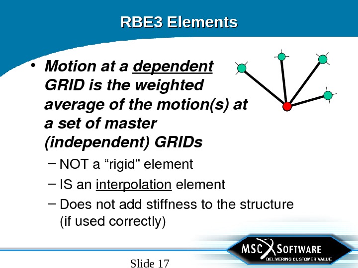
Slide 17 RBE 3 Elements – NOTa“rigid”element – ISan interpolation element – Doesnotaddstiffnesstothestructure (ifusedcorrectly) • Motionata dependent GRIDistheweighted averageofthemotion(s)at asetofmaster (independent)GRIDs
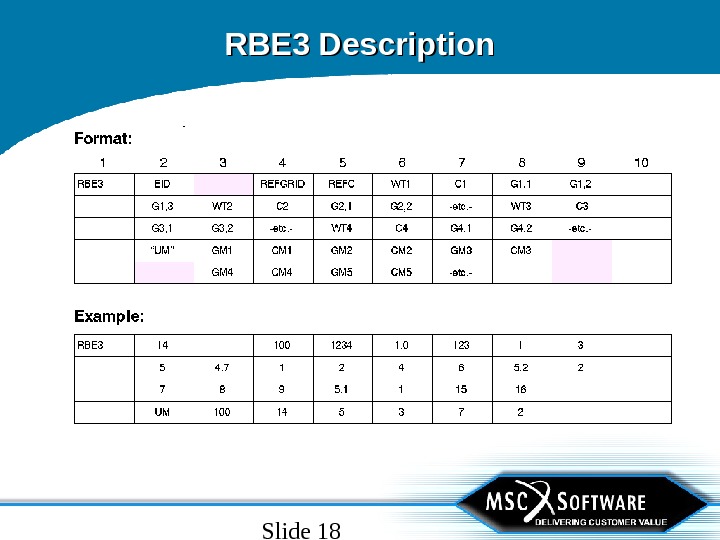
Slide 18 RBE 3 Description
Slide 19 RBE 3 Description • Bydefault, thereferencegrid. DOFwill bethedependent. DOF • Numberofdependent. DOFisequalto thenumberof. DOFonthe. REFCfield • Dependent. DOFcannotbe. SPC’d, OMITted, SUPORTedorbedependent onother. RBE/MPCelements
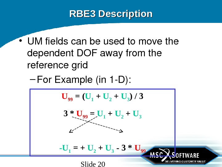
Slide 20 U 99 = ( U 1 + U 2 + U 3 ) / 3 3 * U 99 = U 1 + U 2 + U 3 -U 1 = + U 2 + U 3 — 3 * U 99 RBE 3 Description • UMfieldscanbeusedtomovethe dependent. DOFawayfromthe referencegrid – For. Example(in 1 D):
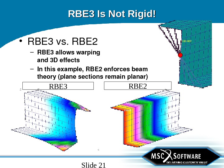
Slide 21 RBE 3 Is Not Rigid! • RBE 3 vs. RBE 2 – RBE 3 allowswarping and 3 Deffects – Inthisexample, RBE 2 enforcesbeam theory(planesectionsremainplanar) RBE 3 R
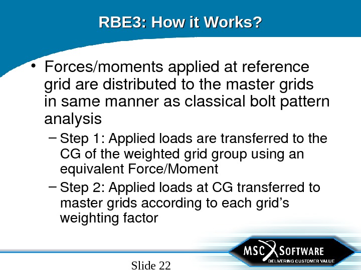
Slide 22 RBE 3: How it Works? • Forces/momentsappliedatreference gridaredistributedtothemastergrids insamemannerasclassicalboltpattern analysis – Step 1: Appliedloadsaretransferredtothe CGoftheweightedgridgroupusingan equivalent. Force/Moment – Step 2: Appliedloadsat. CGtransferredto mastergridsaccordingtoeachgrid’s weightingfactor
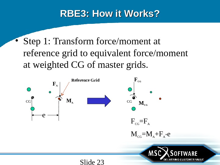
Slide 23 RBE 3: How it Works? • Step 1: Transform force/moment at reference grid to equivalent force/moment at weighted CG of master grids. M CG =M A +F A * e. F CG =F ACG F CG M CGF A M AReference Grid e. CG
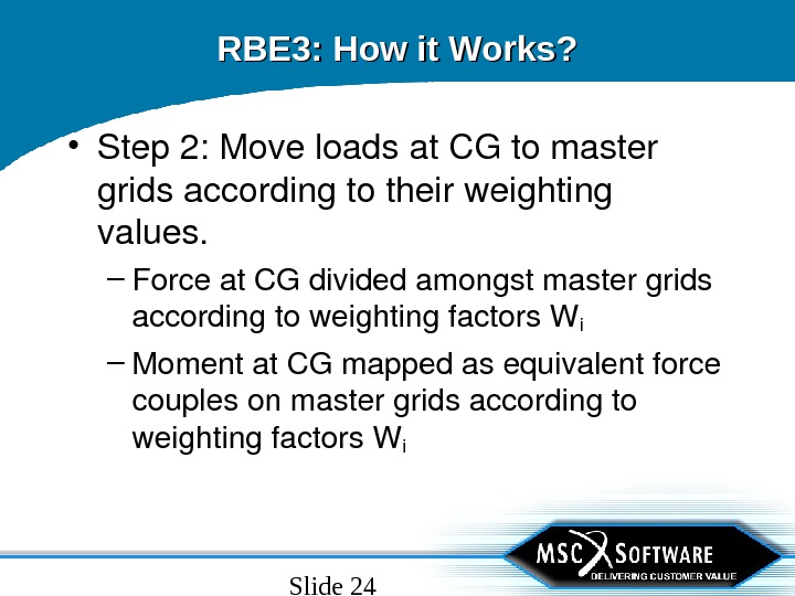
Slide 24 RBE 3: How it Works? • Step 2: Moveloadsat. CGtomaster gridsaccordingtotheirweighting values. – Forceat. CGdividedamongstmastergrids accordingtoweightingfactors. Wi – Momentat. CGmappedasequivalentforce couplesonmastergridsaccordingto weightingfactors. W i
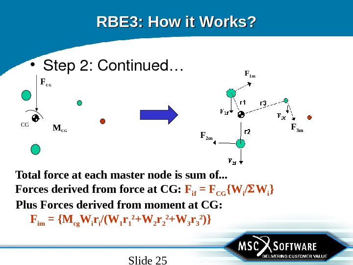
Slide 25 RBE 3: How it Works? • Step 2: Continued… CG F CG M CG Total force at each master node is sum of. . . Forces derived from force at CG: F if = F CG {W i / W i }F 1 m F 3 m F 2 m Plus Forces derived from moment at CG: F im = {M cg W i r i /(W 1 r 1 2 +W 2 r 2 2 +W 3 r 3 2 )}
Slide 26 RBE 3: How it Works? • Massesonreferencegridaresmeared tothemastergridssimilartohowforces aredistributed – Massisdistributedtothemastergridsaccording totheirweightingfactors – Motionofreferencemassresultsininertialforce thatgetstransferredtomastergrids – Referencenodeinertialforceisdistributedin samemanneraswhenstaticforceisappliedto thereferencegrid.
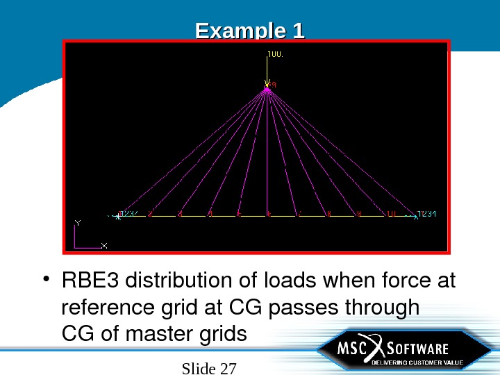
Slide 27 Example 1 • RBE 3 distributionofloadswhenforceat referencegridat. CGpassesthrough CGofmastergrids
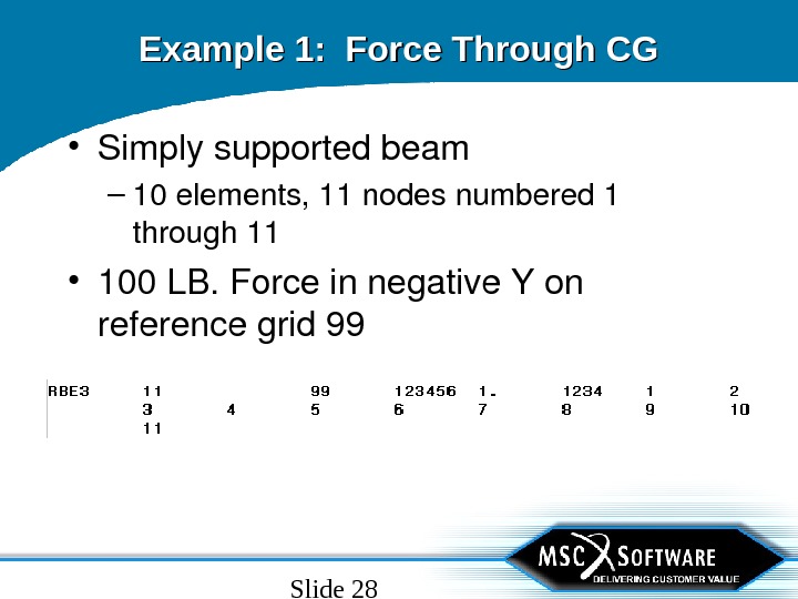
Slide 28 Example 1: Force Through CG • Simplysupportedbeam – 10 elements, 11 nodesnumbered 1 through 11 • 100 LB. Forceinnegative. Yon referencegrid
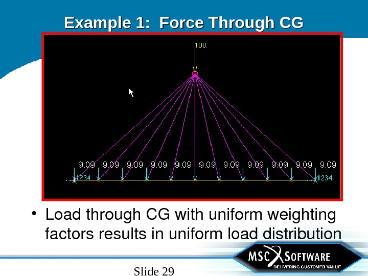
Slide 29 Example 1: Force Through CG • Loadthrough. CGwithuniformweighting factorsresultsinuniformloaddistribution
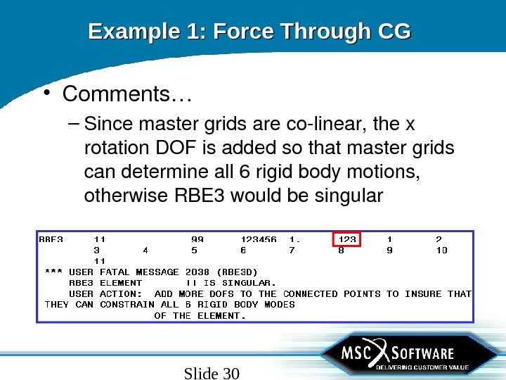
Slide 30 Example 1: Force Through CG • Comments… – Sincemastergridsarecolinear, thex rotation. DOFisaddedsothatmastergrids candetermineall 6 rigidbodymotions, otherwise. RBE 3 wouldbesingular
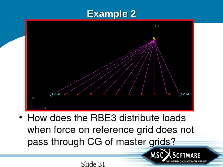
Slide 31 Example 2 • Howdoesthe. RBE 3 distributeloads whenforceonreferencegriddoesnot passthrough. CGofmastergrids?
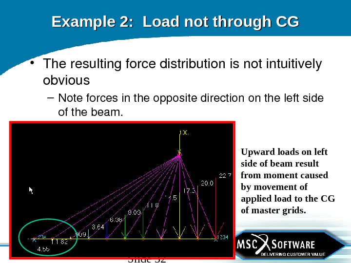
Slide 32 Example 2: Load not through CG • Theresultingforcedistributionisnotintuitively obvious – Noteforcesintheoppositedirectionontheleftside ofthebeam. Upward loads on left side of beam result from moment caused by movement of applied load to the CG of master grids.
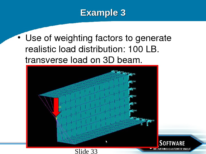
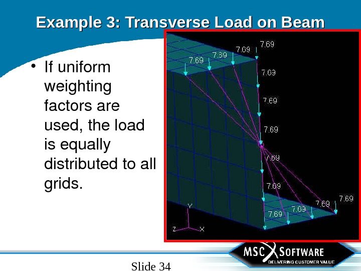
Slide 33 Example 3 • Useofweightingfactorstogenerate realisticloaddistribution: 100 LB. transverseloadon 3 Dbeam.
Slide 34 Example 3: Transverse Load on Beam • Ifuniform weighting factorsare used, theload isequally distributedtoall grids.
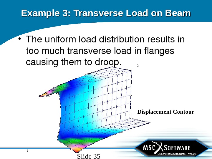
Slide 35 Example 3: Transverse Load on Beam Displacement Contour • Theuniformloaddistributionresultsin toomuchtransverseloadinflanges causingthemtodroop.
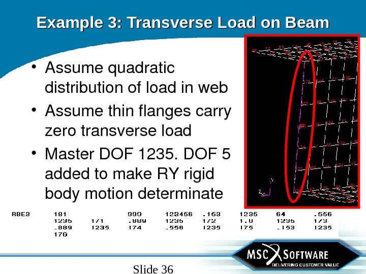
Slide 36 Example 3: Transverse Load on Beam • Assumequadratic distributionofloadinweb • Assumethinflangescarry zerotransverseload • Master. DOF 1235. DOF 5 addedtomake. RYrigid bodymotiondeterminate
Slide 37 • Displacementswithquadraticweighting factorsvirtuallyequivalenttothosefrom RBE 2(Beam. Theory), butdonot impose“planesectionsremainplanar” asdoes. RBE 2. Example 3: Transverse Load on Beam
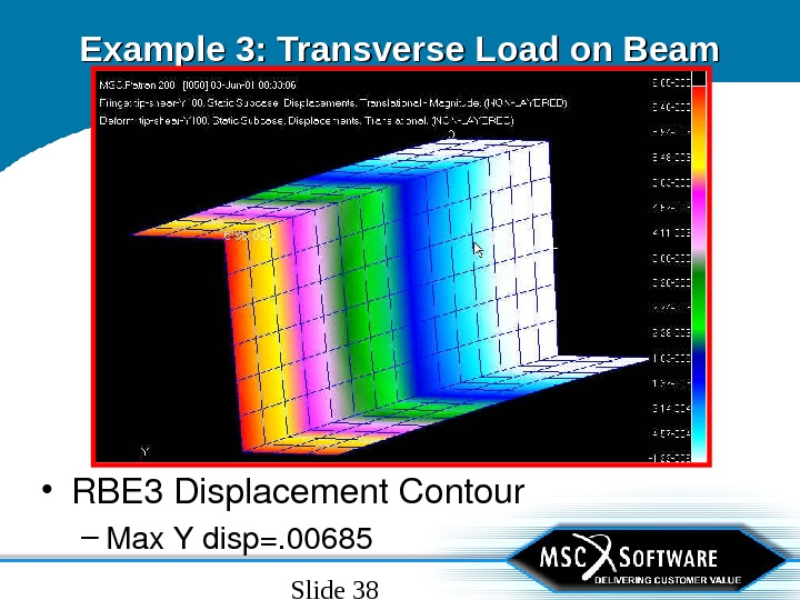
Slide 38 Example 3: Transverse Load on Beam • RBE 3 Displacement. Contour – Max. Ydisp=.
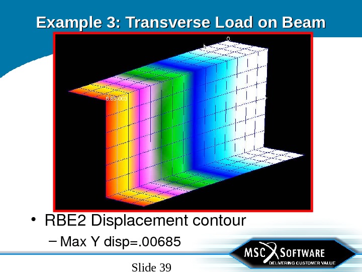
Slide 39 Example 3: Transverse Load on Beam • RBE 2 Displacementcontour – Max. Ydisp=.
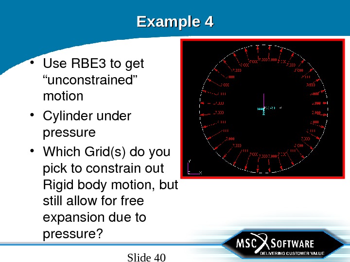
Slide 40 Example 4 • Use. RBE 3 toget “unconstrained” motion • Cylinderunder pressure • Which. Grid(s)doyou picktoconstrainout Rigidbodymotion, but stillallowforfree expansiondueto pressure?
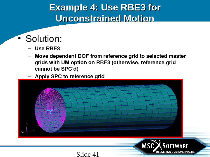
Slide 41 Example 4: Use RBE 3 for Unconstrained Motion • Solution: – Use. RBE 3 – Movedependent. DOFfromreferencegridtoselectedmaster gridswith. UMoptionon. RBE 3(otherwise, referencegrid cannotbe. SPC’d) – Apply. SPCtoreferencegrid
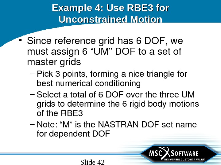
Slide 42 Example 4: Use RBE 3 for Unconstrained Motion • Sincereferencegridhas 6 DOF, we mustassign 6“UM”DOFtoasetof mastergrids – Pick 3 points, forminganicetrianglefor bestnumericalconditioning – Selectatotalof 6 DOFoverthethree. UM gridstodeterminethe 6 rigidbodymotions ofthe. RBE 3 – Note: “M”isthe. NASTRANDOFsetname fordependent. DO
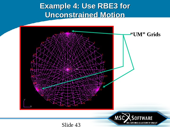
Slide 43 Example 4: Use RBE 3 for Unconstrained Motion “ UM” Grids
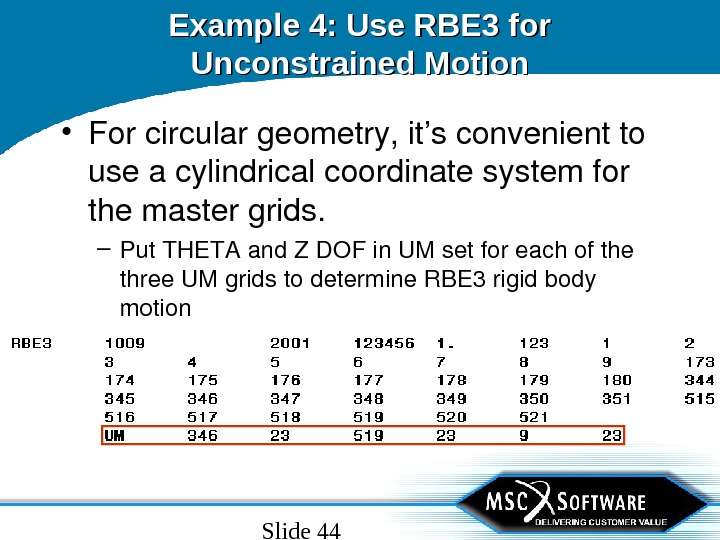
Slide 44 Example 4: Use RBE 3 for Unconstrained Motion • Forcirculargeometry, it’sconvenientto useacylindricalcoordinatesystemfor themastergrids. – Put. THETAand. ZDOFin. UMsetforeachofthe three. UMgridstodetermine. RBE 3 rigidbody motion
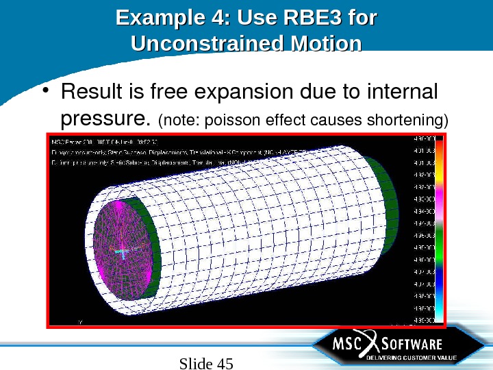
Slide 45 Example 4: Use RBE 3 for Unconstrained Motion • Resultisfreeexpansionduetointernal pressure. (note: poissoneffectcausesshortening)
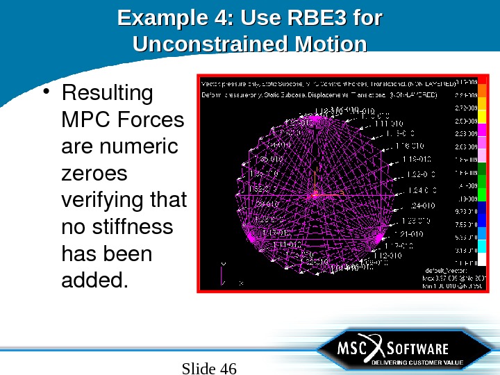
Slide 46 Example 4: Use RBE 3 for Unconstrained Motion • Resulting MPCForces arenumeric zeroes verifyingthat nostiffness hasbeen added.
Slide 47 Example 5 • Connect 3 Dmodeltostickmodel • 3 Dmodelwith 7 psiinternalpressure • Use. RBE 3 insteadof. RBE 2 sothat 3 D modelcanexpandnaturallyatinterface. – RBE 3 willalsoallowwarpingandother 3 D effectsattheinterface.
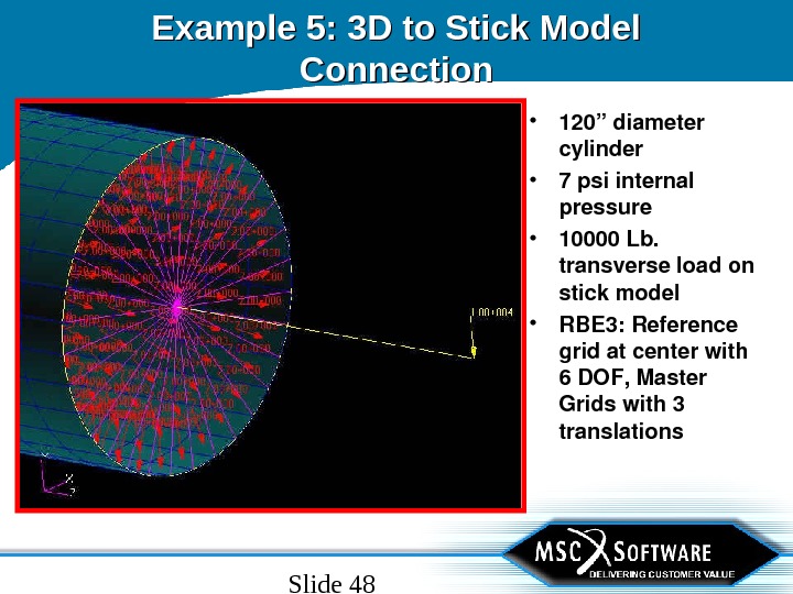
Slide 48 Example 5: 3 D to Stick Model Connection • 120”diameter cylinder • 7 psiinternal pressure • 10000 Lb. transverseloadon stickmodel • RBE 3: Reference gridatcenterwith 6 DOF, Master Gridswith 3 translations
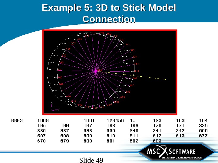
Slide 49 Example 5: 3 D to Stick Model Connection
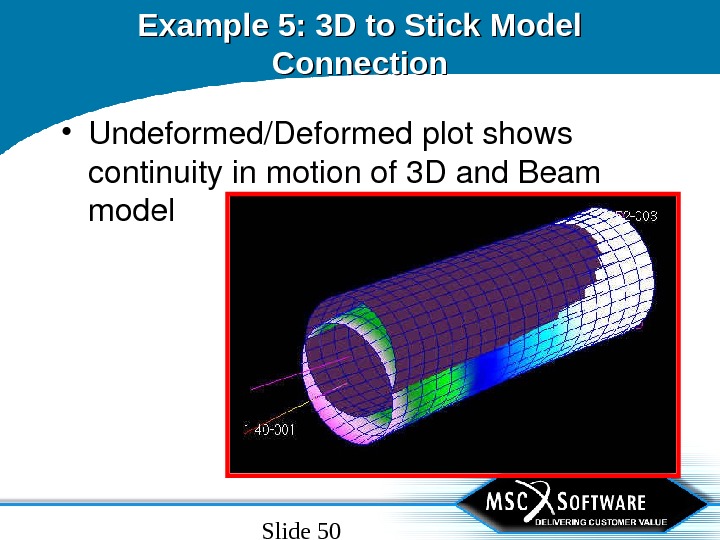
Slide 50 Example 5: 3 D to Stick Model Connection • Undeformed/Deformedplotshows continuityinmotionof 3 Dand. Beam model
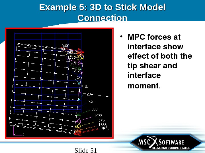
Slide 51 Example 5: 3 D to Stick Model Connection • MPCforcesat interfaceshow effectofboththe tipshearand interface moment.
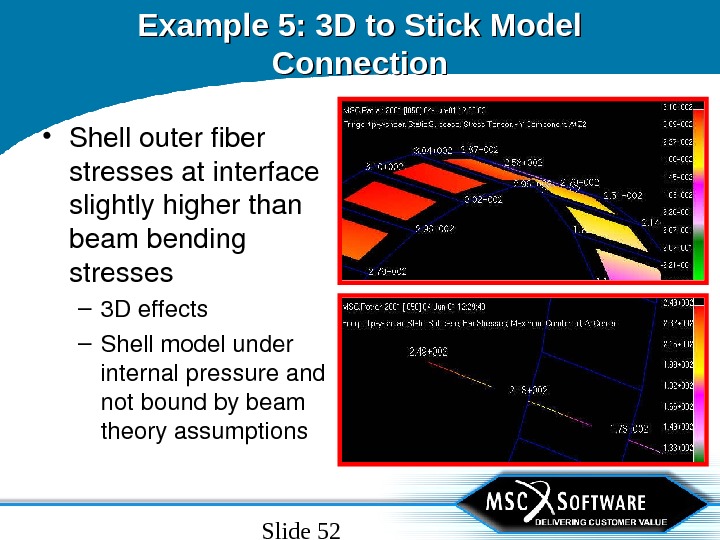
Slide 52 Example 5: 3 D to Stick Model Connection • Shellouterfiber stressesatinterface slightlyhigherthan beambending stresses – 3 Deffects – Shellmodelunder internalpressureand notboundbybeam theoryassumptions
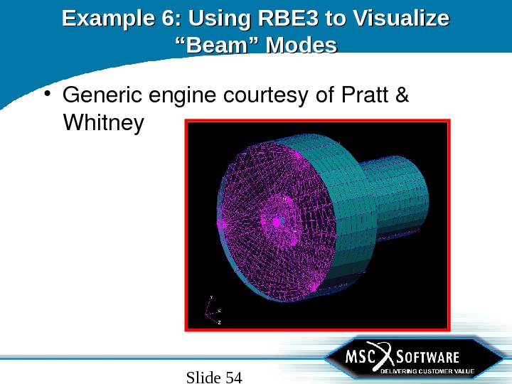
Slide 53 Example 6 • Use. RBE 3 tosee“beam”typemodes fromacomplexmodel • Sometimesit’sdifficulttoidentifyand describemodesofcomplexstructures • Solution: – Connectcomplexstructuredownto centerlinegridswith. RBE 3. – Connectcenterlinegridswith. PLOTELs
Slide 54 Example 6: Using RBE 3 to Visualize “Beam” Modes • Genericenginecourtesyof. Pratt& Whitney
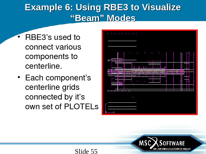
Slide 55 Example 6: Using RBE 3 to Visualize “Beam” Modes • RBE 3’susedto connectvarious componentsto centerline. • Eachcomponent’s centerlinegrids connectedbyit’s ownsetof. PLOTELs
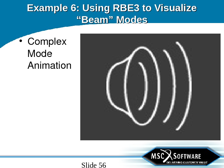
Slide 56 Example 6: Using RBE 3 to Visualize “Beam” Modes • Complex Mode Animation
Slide 57 Example 6: Using RBE 3 to Visualize “Beam” Modes • Animationofthe PLOTEL segments showsthatthis isawhirlmode • Relativemotion ofvarious components moreclearly seen
Slide 58 Example 7 • Use. RBE 3 toconnectincompatible elements – Beamtoplate – Beamtosolid – Platetosolid • Alternativeto. RSSCON
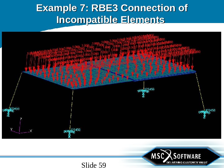
Slide 59 Example 7: RBE 3 Connection of Incompatible Elements
Slide 60 Example 7: RBE 3 Connection of Incompatible Elements • Use. RBE 3 toconnectbeamstoplates attwocorners • Use. RBE 3 toconnectbeamstosolids attwocorners • Use. RBE 3 toconnectplatestosolid – Platethicknessissameassolidthickness inthisexample
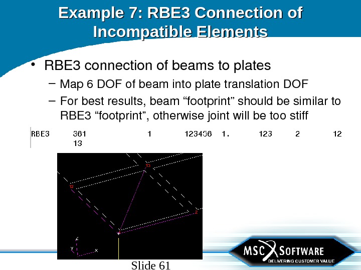
Slide 61 Example 7: RBE 3 Connection of Incompatible Elements • RBE 3 connectionofbeamstoplates – Map 6 DOFofbeamintoplatetranslation. DOF – Forbestresults, beam“footprint”shouldbesimilarto RBE 3“footprint”, otherwisejointwillbetoostiff
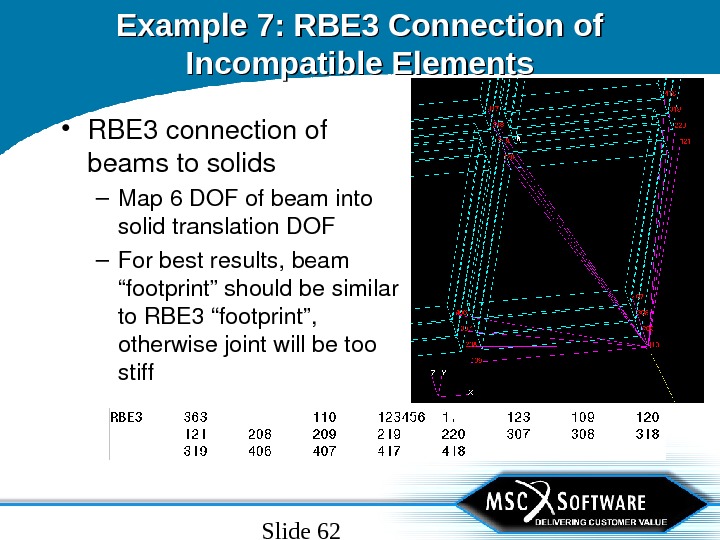
Slide 62 Example 7: RBE 3 Connection of Incompatible Elements • RBE 3 connectionof beamstosolids – Map 6 DOFofbeaminto solidtranslation. DOF – Forbestresults, beam “footprint”shouldbesimilar to. RBE 3“footprint”, otherwisejointwillbetoo stiff
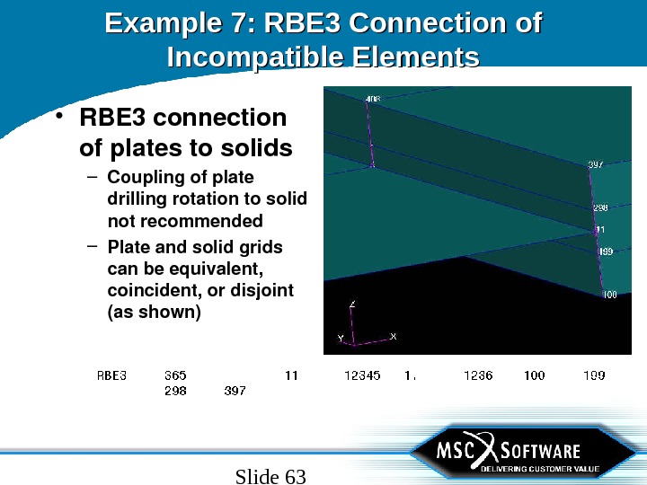
Slide 63 Example 7: RBE 3 Connection of Incompatible Elements • RBE 3 connection ofplatestosolids – Couplingofplate drillingrotationtosolid notrecommended – Plateandsolidgrids canbeequivalent, coincident, ordisjoint (asshown)
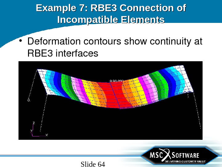
Slide 64 Example 7: RBE 3 Connection of Incompatible Elements • Deformationcontoursshowcontinuityat RBE 3 interfaces
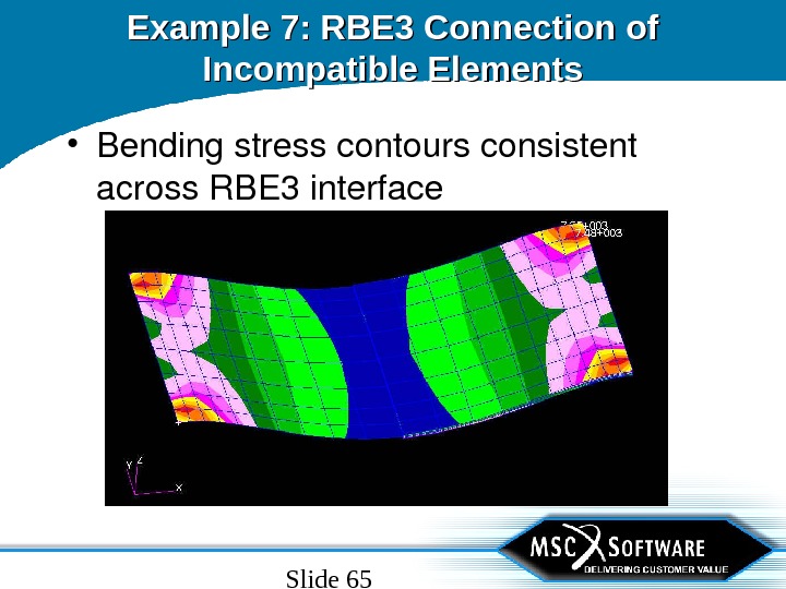
Slide 65 Example 7: RBE 3 Connection of Incompatible Elements • Bendingstresscontoursconsistent across. RBE 3 interface
Slide 66 RBE 3 Usage Guidelines • Donotspecifyrotational. DOFfor mastergridsexceptwhennecessaryto avoidsingularitycausedbyalinearset ofmastergrids • Usingrotational. DOFonmastergrids canresultinimplausibleresults(see nexttwoslides)
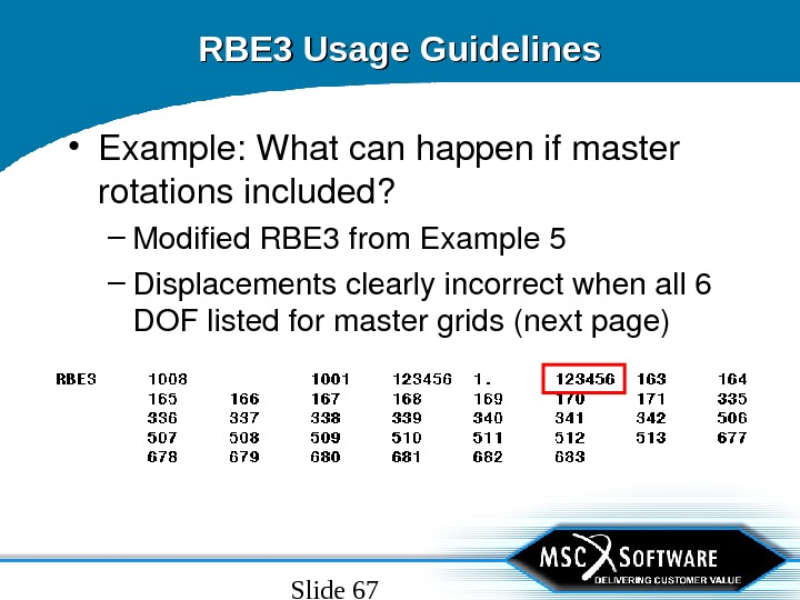
Slide 67 RBE 3 Usage Guidelines • Example: Whatcanhappenifmaster rotationsincluded? – Modified. RBE 3 from. Example 5 – Displacementsclearlyincorrectwhenall 6 DOFlistedformastergrids(nextpage)
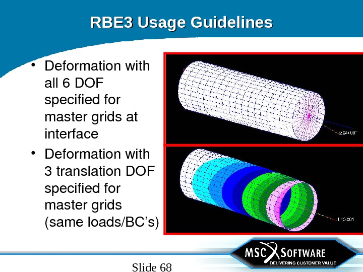
Slide 68 RBE 3 Usage Guidelines • Deformationwith all 6 DOF specifiedfor mastergridsat interface • Deformationwith 3 translation. DOF specifiedfor mastergrids (sameloads/BC’s)
Slide 69 RBE 3 Usage Guidelines • Makecheckrunwith PARAM, CHECKOUT, YES – Section 9. 4. 1 of. MSC. Nastran. Reference. Manual(V 68) – EMHprintoutshouldbenumericzeroes(nogrounding) – No. MAXRATIOerrormessagesfromdecompositionof. R g mm and. R m mm matrices(numericallystable) • Performgroundingcheckofatleast. K GG and. K NN matrix – V 2001: Casecontrolcommand • GROUNDCHECK(SET=(G, N))=YES – V 70. 7 andearlier: • Use. CHECKAaltersfrom. SSSALTERlibrary
Slide 70 RBE 3: Additional Reading • Much. RBE 3 informationhasbeenpostedon MSC’s. Knowledge. Base – http: //www. mechsolutions. com/support/ knowbase /index. html
Slide 71 RBE 3: Additional Reading • Recommended. TANs – TAN#: 2402 RBE 3 The. Interpolation. Element. – TAN#: 3280 RBE 3 ELEMENTCHANGESINVERSION 70. 5, improveddiagnostics – TAN#: 4155 RBE 3 ELEMENTCHANGESINVERSION 70. 7 – TAN#: 4494 Mathematical. Specificationofthe. Modern RBE 3 Element – TAN#: 4497 ANECONOMICALMETHODTOEVALUATE RBE 3 ELEMENTSINLARGESIZEMODELS
Slide 72 User-Input based “Rigid” Elements • MPCs – Mostgeneralpurposewaytodefine motionbasedrelationships – Could beusedinplaceof. ALLother. RBEi • Lackofgeometrymakesthisimpractical – Canbechangedbetween. SUBCASEs
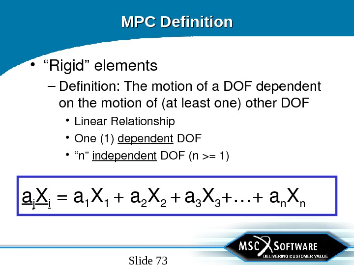
Slide 73 MPC Definition • “ Rigid”elements – Definition: Themotionofa. DOFdependent onthemotionof(atleastone)other. DOF • Linear. Relationship • One(1) dependent DOF • “ n” independent DOF(n>=1) a j X i =a 1 X 1 +a 2 X 2 + a 3 X 3 +…+a n X n
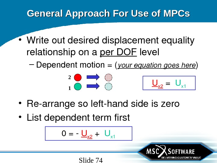
Slide 74 General Approach For Use of MPCs • Writeoutdesireddisplacementequality relationshipona per. DOF level – Dependentmotion=( yourequationgoeshere ) 0= U x 2 + U x 1 • Rearrangesolefthandsideiszero • Listdependenttermfirst U x 2 = U x
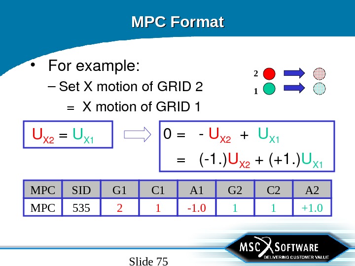
Slide 75 MPC Format • Forexample: – Set. Xmotionof. GRID 2 =Xmotionof. GRID 1 U X 2 = U X 1 0 = U X 2 + U X 1 = (1. ) U X 2 +(+1. ) U X 1 1 +1. 0 -1. 0 12 1 MPC 535 C 2 A 2 A 1 G 2 G 1 C 1 MPC SI
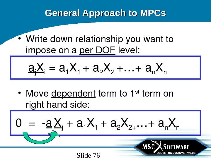
Slide 76 General Approach to MPCs • Writedownrelationshipyouwantto imposeona per. DOF level: a j X i =a 1 X 1 +a 2 X 2 +…+a n X n 0= a i X i +a 1 X 1 +a 2 X 2+ …+a n X n • Move dependent termto 1 st termon righthandside:
Slide 77 Why would I want to use an MPC? • Tie GRIDstogether(RBEi) • Determine relative motionbetween GRIDs • Maintain separationbetween. GRIDs • Determine average motionbetween GRIDs • Model bellcrankorcontrolsystem • Unitsconversion
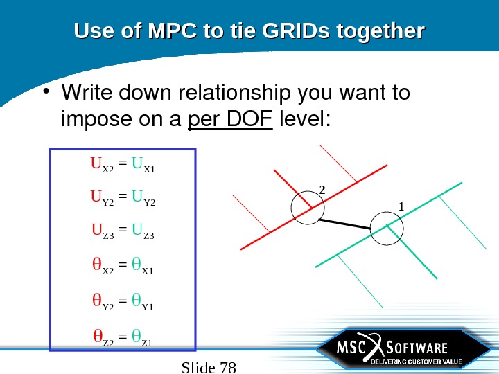
Slide 78 Use of MPC to tie GRIDs together • Writedownrelationshipyouwantto imposeona per. DOF level: U X 2 = U X 1 U Y 2 = U Y 2 U Z 3 = U Z 3 X 2 = X 1 Y 2 = Y 1 Z 2 = Z
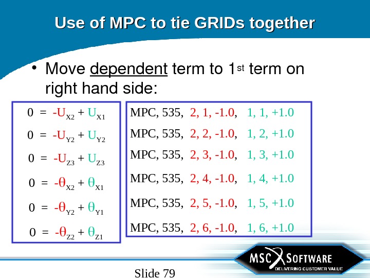
Slide 79 MPC, 535, 2, 1, -1. 0 , 1, 1, +1. 0 MPC, 535, 2, 2, -1. 0 , 1, 2, +1. 0 MPC, 535, 2, 3, -1. 0 , 1, 3, +1. 0 MPC, 535, 2, 4, -1. 0 , 1, 4, +1. 0 MPC, 535, 2, 5, -1. 0 , 1, 5, +1. 0 MPC, 535, 2, 6, -1. 0 , 1, 6, +1. 0 Use of MPC to tie GRIDs together • Move dependent termto 1 st termon righthandside: 0 = -U X 2 + U X 1 0 = -U Y 2 + U Y 2 0 = -U Z 3 + U Z 3 0 = — X 2 + X 1 0 = — Y 2 + Y 1 0 = — Z 2 + Z
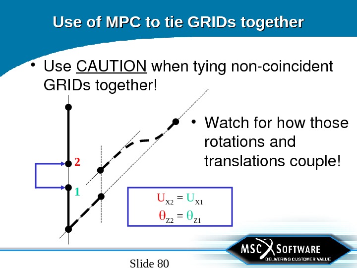
Slide 80 Use of MPC to tie GRIDs together • Use CAUTION whentyingnoncoincident GRIDstogether! • Watchforhowthose rotationsand translationscouple!2 1 U X 2 = U X 1 Z 2 = Z
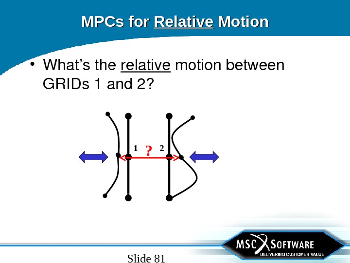
Slide 81 MPCs for Relative Motion • What’sthe relative motionbetween GRIDs 1 and 2? 1 2 ?
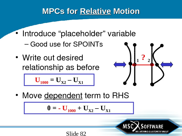
Slide 82 MPCs for Relative Motion • Introduce“placeholder”variable – Goodusefor. SPOINTs 1 2? • Move dependent termto. RHS 0 = — U 1000 + U X 2 – U X 1 • Writeoutdesired relationshipasbefore U 1000 = U X 2 – U X
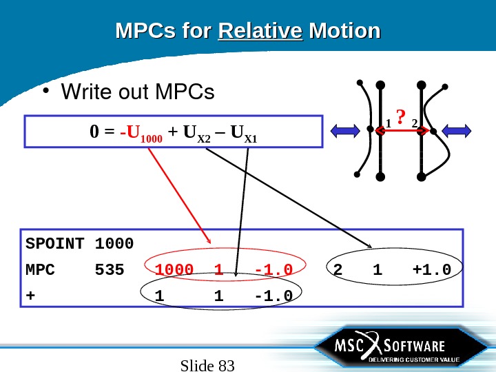
Slide 83 MPCs for Relative Motion • Writeout. MPCs 1 2? 0 = -U 1000 + U X 2 – U X 1 SPOINT 1000 MPC 535 1000 1 -1. 0 2 1 +1. 0 + 1 1 -1.
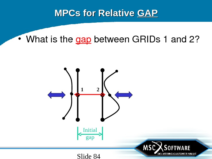
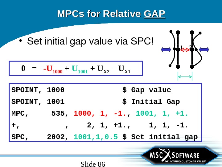
Slide 84 Initial gap. MPCs for Relative GAPGAP • Whatisthe gap between. GRIDs 1 and 2?
Slide 85 MPCs for Relative GAPGAP 1 2 U GAP = U INIT + U X 2 – U X 1 0 = -U GAP + U INIT + U X 2 – U X 1 • Writeequation: – Introducenewplaceholder variableforinitialgap
Slide 86 MPCs for Relative GAPGAP • Setinitialgapvaluevia. SPC! 1 2 SPOINT, 1000 $ Gap value SPOINT, 1001 $ Initial Gap MPC, 535, 1000, 1, -1. , 1001, 1, +1. +, , 2, 1, +1. , 1, 1, -1. SPC, 2002, 1001, 1, 0. 5 $ Set initial gap 0 = -U 1000 + U 1001 + U X 2 – U X
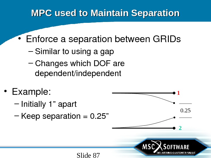
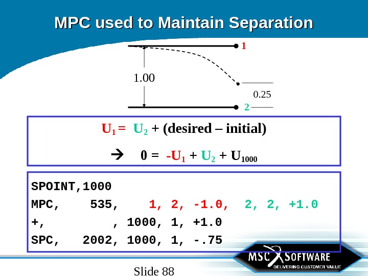
Slide 87 MPC used to Maintain Separation • Enforceaseparationbetween. GRIDs – Similartousingagap – Changeswhich. DOFare dependent/independent • Example: – Initially 1”apart – Keepseparation=0. 25” 1 2 0.
Slide 88 MPC used to Maintain Separation 1 2 0. 25 U 1 = U 2 + (desired – initial) 0 = -U 1 + U 2 + U 1000 SPOINT, 1000 MPC, 535, 1, 2, -1. 0, 2, 2, +1. 0 +, , 1000, 1, +1. 0 SPC, 2002, 1000, 1, -. 75 1.
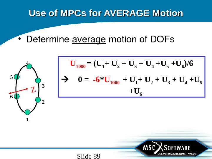
Slide 89 Use of MPCs for AVERAGE Motion • Determine average motionof. DOFs U 1000 = (U 1 + U 2 + U 3 + U 4 +U 5 +U 6 )/6 0 = -6 * U 1000 + U 1 + U 2 + U 3 + U 4 +U 5 +U 6 Z
Slide 90 MPCs as Bell-crank or Control System • Outputof 1 DOFscalesanother U 2 = U 1 /1. 65 0 = -1. 65 * U 2 + U 121 1 +1. 0 -1. 65 12 1 MPC 535 C 2 A 2 A 1 G 2 G 1 C 1 MPC SID 1. 6 5 1.
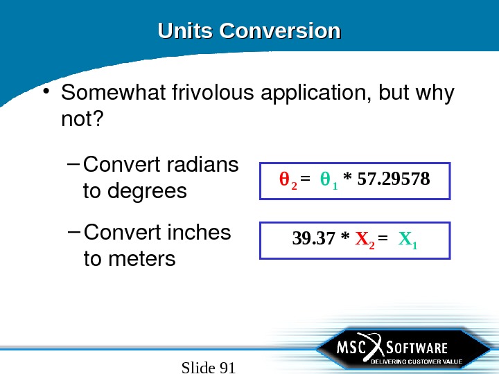
Slide 91 Units Conversion • Somewhatfrivolousapplication, butwhy not? – Convertradians todegrees 2 = 1 * 57. 29578 – Convertinches tometers 39. 37 * X 2 = X
Slide 92 Rigid Element Output • Since. Rigidelementsareaspecialized inputof. MPCequations, theoutputis requestedby. MPCFORCEcasecontrol command. – COMMONERROR • The. MPCFORCEsareassociatedwith. GRID IDs, not. Element. IDs. Sowhenselectinga SETforoutput, besurethesetisfor. GRIDIDs, not. Element. IDs.
Slide 93 Guidelines for “Rigid” Elements • Linear. ONLY – Relationshipscalculatedbasedon initial geometry • Cancauseinternalconstraintsfor thermalconditions • Becarefulthatindependent. GRIDhas 6 DO
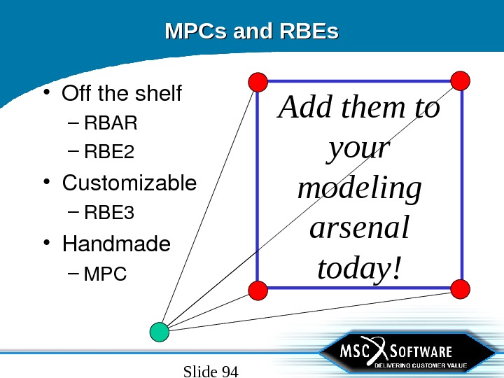
Slide 94 MPCs and RBEs • Offtheshelf – RBAR – RBE 2 • Customizable – RBE 3 • Handmade – MPC Add them to your modeling arsenal today!