

0b9430abd6cdf79aa65d6a07135a8e8e.ppt
- Количество слайдов: 72
 Proton Driver: Prospects in the U. S. Giorgio Apollinari, FNAL 7 th International Workshop on Neutrino Factories and Superbeams Frascati, June 21 st – 26 th, 2005
 Outline • APS Neutrino Study – Open Questions & Recommendations • Brookhaven Super Neutrino Beam Proposal – Front End and SC Linac & AGS Upgrade • Fermilab Proton Driver Proposal – 8 Ge. V SCRF Linac (bulk of the talk) – R&D Effort – PD/ILC Synergy • Conclusion
 Neutrinos are Everywhere • Neutrinos outnumber ordinary matter particles in the Universe (electrons, protons, neutrons) by a factor of ten billion. • Depending on their masses they may account for a few % of the unknown “dark matter” in the Universe. • Neutrinos are important for stellar dynamics: ~7 1010 cm-2 s-1 stream through the Earth from the sun. • Neutrinos also govern Supernovae dynamics, and hence heavy element production. • If there is CP Violation in the neutrino sector, then neutrino physics might ultimately be responsible for Baryogenesis. To understand the nature of the Universe in which we live we must understand the properties of the neutrino
 APS Neutrino Study • Interdivisional Study – APS, DNP, DPF, DAP, . . • Charges – Examine broad sweep of n physics – Create scientific roadmap for n physics – Move toward agreement ion the next steps. matrix n: 1. 2. 3. 4. Something within or from which something else originates, develops or takes form The natural material in which something is embedded Womb A rectangular array of mathematical elements
 n Open Questions From the US APS Multi-Divisional Study on the Physics of Neutrinos • What are the masses of the neutrinos? • What is the pattern of mixing among the different types of neutrinos? • Are neutrinos their own antiparticles? • Do neutrinos violate the symmetry CP? • Are there “sterile” neutrinos? • Do neutrinos have unexpected or exotic properties? • What can neutrinos tell us about the models of new physics beyond the Standard Model?
 Recommendations + Neutrinoless Nuclear Double Beta Decay & Sun n Energy Spectrum Measurement
 Why Multi-MW Beams ? • Need high beam power to study rare processes – Upper limit on nm - ne oscillation amplitude is ~5%
 US n Superbeams Proposals The AGS-Based Super Neutrino Beam Facility Brookhaven National Laboratory An 8 Ge. V Super. Conducting Linac Proton Driver Fermi National Accelerator Laboratory
 AGS Upgrade with CCL and SCL To RHIC To Target Station High Intensity Source plus RFQ 201. 25 MHz DTL 805 MHz CCL BOOSTER AGS 116 Me. V 1. 5 Ge. V - 28 Ge. V 0. 4 s cycle time (2. 5 Hz) 400 Me. V 800 MHz Superconducting Linac 1. 5 Ge. V • • 0. 2 s Add CCL from 116 Me. V to 400 Me. V SCL from 400 Me. V to 1. 5 Ge. V at 25 Me. V/m gradient One type of cavity, cryomodule and klystron similar to SNS 2. 5 Hz AGS Repetition rate – Triple existing main magnet power supply and current feeds – Double RF power and accelerating gradient
 Injection Schemes 1. 5 -Ge. V Booster 0. 6 sec AGS 28 -Ge. V AGS 200 -Me. V TDL 2. 4 sec Booster 1. 2 Ge. V SCL AGS present AGS upgrade HI Tandem 0. 4 sec Kin. Energy 28 Ge. V Rep. Rate 1 / 3 Hz 2. 5 Hz 0. 67 x 1014 0. 89 x 1014 Protons/ Cycle Ave. Power Typical DTL cycle for Protons 0. 4 sec 0. 10 MW 1 x 720 µs @ 30 m. A
 AGS (1 MW) J-PARC • Total beam power") AGS Proton Driver Parameters AGS (now) AGS (1 MW) J-PARC • Total beam power [MW] 0. 14 1. 00 0. 75 • Injector Energy [Ge. V] 1. 5 1. 2 3. 0 • Beam energy [Ge. V] 24 28 50 • Average current [m. A] 6 36 15 • Cycle time [s] 2 0. 4 3. 4 • No. of protons per fill 0. 7 1014 0. 9 1014 • Ave. circulating current [A] 4. 2 5. 0 12 • No. of bunches at extraction 6 23 8 • No. of protons per bunch 1 1013 0. 4 1013 • No. of protons per 107 sec. 3. 5 1020 23 1020 3. 3 1014 4 1013 10
AGS Proton Driver Parameters AGS (now) AGS (1 MW) J-PARC • Total beam power [MW] 0. 14 1. 00 0. 75 • Injector Energy [Ge. V] 1. 5 1. 2 3. 0 • Beam energy [Ge. V] 24 28 50 • Average current [m. A] 6 36 15 • Cycle time [s] 2 0. 4 3. 4 • No. of protons per fill 0. 7 1014 0. 9 1014 • Ave. circulating current [A] 4. 2 5. 0 12 • No. of bunches at extraction 6 23 8 • No. of protons per bunch 1 1013 0. 4 1013 • No. of protons per 107 sec. 3. 5 1020 23 1020 3. 3 1014 4 1013 10
 1. 2 Ge. V Superconducting Linac • Beam energy 0. 2 0. 4 Ge. V 0. 4 0. 8 Ge. V 0. 8 1. 2 Ge. V • RF frequency 805 MHz • Acc. gradient 10. 8 Me. V/m • Length 37. 8 m 41. 4 m • Beam power (exit) 17 k. W 1610 MHz 23. 5 Me. V/m 38. 3 m 34 k. W 50 k. W Based on SNS Experiences
 AGS System Upgrade • Beam Dynamics in AGS – – – Injection Painting Linac Emittance Improvement Transition Crossing Ring Impedances Beam Collimation and Ringing • AGS Magnet Test • New Power Supply Design • AGS RF Cavity Design AGS Injection Simulation
 Neutrino Beam Production • 1 MW He gas-cooled Carbon target • New horn design • Target Hill for Radiation Protection • Target on 11. 30 downhill to aim at Homestake mine • Beam dump well above ground water table to avoid activation • Near Detector Beam Monitoring
 FNAL Director Vision • FNAL will be center of US HEP in ~2010 IF (ILC Cost Looks Affordable –CDR 2006) THEN – Push for ILC ~2010 Construction start at FNAL – Execute 120 Ge. V Neutrino Program at ~1 MW ELSE – Superconducting 8 Ge. V Proton Driver starting ~2008 – 30 -120 Ge. V and 8 Ge. V beams at 2 -4 MW after 2012 – Stepping-stone to delayed ILC construction starting in ~2012 ENDIF
 FNAL Director Vision P. Oddone – EPP 2010
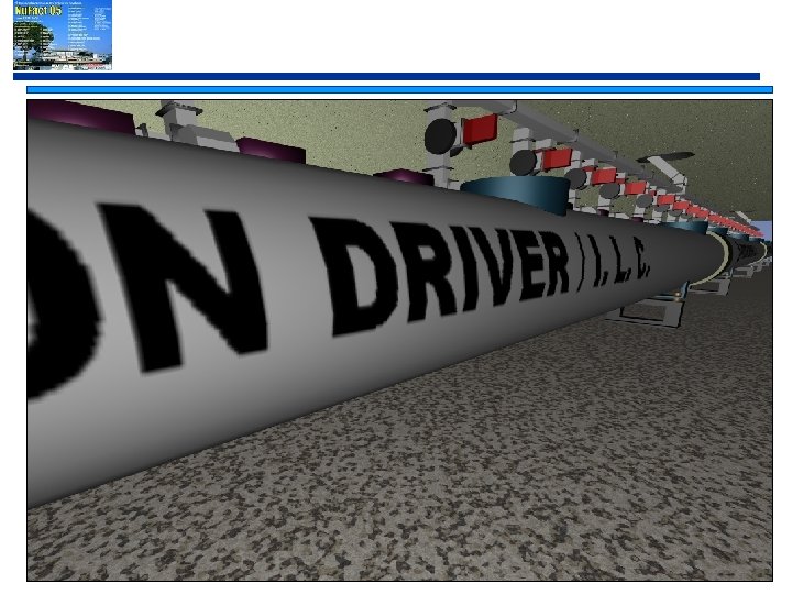
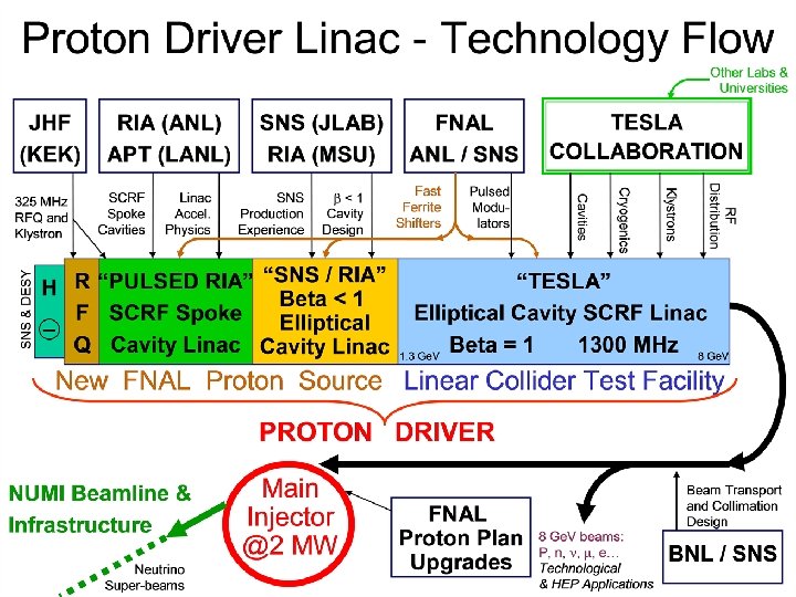
 Proton Driver Idea • New* idea incorporating concepts from the ILC, the Spallation Neutron Source, RIA and APT. – Copy SNS, RIA, and JPARC Linac design up to 1. 3 Ge. V – Use ILC Cryomodules from 1. 3 - 8 Ge. V – H- Injection at 8 Ge. V in Main Injector • “Super Beams” in Fermilab Main Injector: – 2 MW Beam power at both 8 Ge. V and 120 Ge. V – Small emittances ==> Small losses in Main Injector – Minimum (1. 5 sec) cycle time (or less) – MI Beam Power Independent of Beam Energy: flexible program * The 8 Ge. V Linac concept actually originated with Vinod Bharadwaj and Bob Noble in 1994, when it made no sense because the SCRF gradients weren’t there. Revived and expanded by G. W. Foster in 2004
 8 Ge. V Superconducting Linac Neutrino “Super. Beams” NUMI SY-120 Fixed. Target Off. Axis 8 Ge. V neutrino 8 Ge. V Linac ~ 700 m Active Length Main Injector @2 MW
 MI with Synchrotron. vs. MI with SCL • MI maintains 2 MW Beam power at lower energy – # of n not strongly dependent on E – Reduces tails at higher n energies • Allow flexible n Program
 Two Design Points for 8 Ge. V Linac Initial: 0. 5 MW Linac Beam Power (BASELINE) 8. 3 m. A x 3 msec x 2. 5 Hz x 8 Ge. V = 0. 5 MW Twelve Klystrons Required Ultimate: 2 MW Linac Beam Power 25 m. A x 1 msec x 10 Hz x 8 Ge. V = 2. 0 MW 33 Klystrons Required Either Option Supports: 1. 5 E 14 x 0. 7 Hz x 120 Ge. V = 2 MW Beam Power from Fermilab Main Injector
 Motivations for Linac Proton Driver • Protons on Target for Neutrino Program • 2 MW at 30 -120 Ge. V from the Main Injector • 0. 5 - 2 MW at 8 Ge. V directly from the Linac • Clear path for further MI upgrades > 2 MW Linac Provides All Three • Synergy with International Linear Collider – Exactly the same technology for E ~ 1. 5 - 8 Ge. V – 1. 5% Scale Demonstration Project & U. S. Cost Basis – Seed Project for U. S. Industrialization of SCRF
 449 Cavities") 0. 5 MW Initial 8 Ge. V Linac 11 Klystrons (2 types) 449 Cavities 51 Cryomodules “PULSED RIA” 325 MHz 0 -110 Me. V β<1 TESLA LINAC 1300 MHz 0. 1 -1. 2 Ge. V 2 Klystrons 96 Elliptical Cavities 12 Cryomodules 10 MW TESLA Klystrons Multi-Cavity Fanout at 10 - 50 k. W/cavity Phase and Amplitude Control w/ Ferrite Tuners H- RFQ MEBT RTSR SSR DSR Modulator Elliptical Option 48 Cavites / Klystron DSR 10 MW TESLA Multi-Beam Klystrons β=. 47 β=. 61 β=. 81 or… 325 MHz Spoke Resonators TESLA LINAC 1300 MHz Modulator Single Modulator 3 MW JPARC Klystron Front End Linac Modulator β=1 8 Cavites / Cryomodule 8 Klystrons 288 Cavities in 36 Cryomodules Modulator 36 Cavites / Klystron β=1 β=1 β=1 β=1 β=1 Modulator β=1 β=1 β=1 β=1 β=1
0. 5 MW Initial 8 Ge. V Linac 11 Klystrons (2 types) 449 Cavities 51 Cryomodules “PULSED RIA” 325 MHz 0 -110 Me. V β<1 TESLA LINAC 1300 MHz 0. 1 -1. 2 Ge. V 2 Klystrons 96 Elliptical Cavities 12 Cryomodules 10 MW TESLA Klystrons Multi-Cavity Fanout at 10 - 50 k. W/cavity Phase and Amplitude Control w/ Ferrite Tuners H- RFQ MEBT RTSR SSR DSR Modulator Elliptical Option 48 Cavites / Klystron DSR 10 MW TESLA Multi-Beam Klystrons β=. 47 β=. 61 β=. 81 or… 325 MHz Spoke Resonators TESLA LINAC 1300 MHz Modulator Single Modulator 3 MW JPARC Klystron Front End Linac Modulator β=1 8 Cavites / Cryomodule 8 Klystrons 288 Cavities in 36 Cryomodules Modulator 36 Cavites / Klystron β=1 β=1 β=1 β=1 β=1 Modulator β=1 β=1 β=1 β=1 β=1
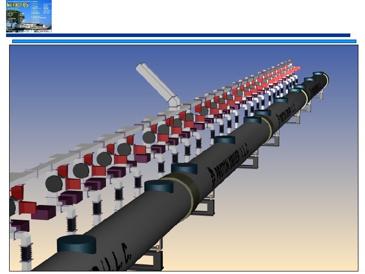
 Building Block of the 8 Ge. V Linac … is the TESLA RF Station: • 36 SCRF CAVITIES • ~ 4 Cryomodules • 1 Klystron • 1 Modulator • ~1 Ge. V of Beam Energy Modulator β=1 β=1 β=1 Extending this technology to Proton Linacs is the Key to the Proton Driver.
 Upgrade Equipment • Initial 0. 5 MW Gallery is nearly empty – One Klystron every 180 feet • Ultimate 2 MW Gallery is comfortable – One Klystron every 60 feet
 449 Cavities") 0. 5 MW Initial 8 Ge. V Linac 11 Klystrons (2 types) 449 Cavities 51 Cryomodules “PULSED RIA” 325 MHz 0 -110 Me. V β<1 TESLA LINAC 1300 MHz 0. 1 -1. 2 Ge. V 2 Klystrons 96 Elliptical Cavities 12 Cryomodules 10 MW TESLA Klystrons Multi-Cavity Fanout at 10 - 50 k. W/cavity Phase and Amplitude Control w/ Ferrite Tuners H- RFQ MEBT RTSR SSR DSR Modulator Elliptical Option 48 Cavites / Klystron DSR 10 MW TESLA Multi-Beam Klystrons β=. 47 β=. 61 β=. 81 or… 325 MHz Spoke Resonators TESLA LINAC 1300 MHz Modulator Single Modulator 3 MW JPARC Klystron Front End Linac Modulator β=1 8 Cavites / Cryomodule 8 Klystrons 288 Cavities in 36 Cryomodules Modulator 36 Cavites / Klystron β=1 β=1 β=1 β=1 β=1 Modulator β=1 β=1 β=1 β=1 β=1
0. 5 MW Initial 8 Ge. V Linac 11 Klystrons (2 types) 449 Cavities 51 Cryomodules “PULSED RIA” 325 MHz 0 -110 Me. V β<1 TESLA LINAC 1300 MHz 0. 1 -1. 2 Ge. V 2 Klystrons 96 Elliptical Cavities 12 Cryomodules 10 MW TESLA Klystrons Multi-Cavity Fanout at 10 - 50 k. W/cavity Phase and Amplitude Control w/ Ferrite Tuners H- RFQ MEBT RTSR SSR DSR Modulator Elliptical Option 48 Cavites / Klystron DSR 10 MW TESLA Multi-Beam Klystrons β=. 47 β=. 61 β=. 81 or… 325 MHz Spoke Resonators TESLA LINAC 1300 MHz Modulator Single Modulator 3 MW JPARC Klystron Front End Linac Modulator β=1 8 Cavites / Cryomodule 8 Klystrons 288 Cavities in 36 Cryomodules Modulator 36 Cavites / Klystron β=1 β=1 β=1 β=1 β=1 Modulator β=1 β=1 β=1 β=1 β=1
 Main Parameter Decisions 1. Main Injector Beam: (1. 5 E 14, 1. 5 sec, 2 MW) 2. Pulse Parameters: ( 8 m. A x 3 msec x 2. 5 Hz) 1. Ultimate Upgrade: (25 m. A x 1 msec x 10 Hz) 3. Operating Frequency: (1300 MHz / 325 MHz) 4. Copper – to – SCRF transition: (15 Me. V) 5. Spokes–to–Elliptical transition: (110 - 400 Me. V) 6. Design Margins on 8 Ge. V H- Transport
 3. Linac Operating Frequencies Following the selection of the Cold SCRF Option for the ILC, We have chosen TESLA/XFEL Compatible Frequencies: • 1300 MHz Main Linac (= ILC / TESLA / XFEL) • 325 MHz (=1300 MHz/4) Front-End Linac (= JPARC) Valuable assets at these frequencies: 1. SRF Cavities 2. RF Couplers 3. Cryomodule Designs 4. Klystrons (multi-year development) 5. Front-End Linac Designs (325 MHz) 6. Collaborators (e. g. ILC, Euro-XFEL, JPARC…) (a gift ! )
 4. Copper-to-SCRF Transition • We have chosen 15 Me. V (RFQ + warm TSRs. ) – – – Much lower than SNS ( ~ 186 Me. V) Allows Single Klystron to drive linac up to 110 Me. V Leverages uses of Fast Phase Shifters to produce many channels of RF from a single Klystron • Previous Design Study assumed 85 Me. V DTL – – – Conventional Solution, still valid Modified Commercial Product at 325 MHz Required 7 Klystrons, $30 M + contingency etc.
 325 MHz Front-End Linac Single Klystron Feeds SCRF Linac to E > 100 Me. V SCRF Spoke Resonator Cryomodules Charging Supply MEBT RFQ Ferrite Tuners RF Distribution Waveguide Modulator Capacitor / Switch / Bouncer 115 k. V Pulse Transformer 325 MHz Klystron – Toshiba E 3740 A (JPARC)
 6. 8 Ge. V H- Transport 1. 8 Ge. V H- Transport is new to accelerators 2. Issues: 1. 2. Blackbody Stripping 3. Foil Lifetime 4. 3. Magnetic Stripping Injection losses Mini-Workshop Dec 9 -10, 2004 Conclusion: no problems with baseline design http: //www-bd. fnal. gov/pdriver/H-workshop/hminus. html
 Margin on H- Magnetic Stripping • Stripping Probability 10 -9/m at 500 Gauss, 8 Ge. V • Beam Line Should Operate Acceptably at 9 -10 Ge. V photon distribution 0. 75 e. V cross section One milliwatt/m of Beam Loss per Megawatt of Beam Power
 • Parameter List gives subsystem details for technically feasible") Linac Segment Details (for reference) • Parameter List gives subsystem details for technically feasible baseline http: //tdserver 1. fnal. gov/8 gevlinac. Papers/Parameter. List 2005/CD 0_Parameter_List_Current_Version. pdf
Linac Segment Details (for reference) • Parameter List gives subsystem details for technically feasible baseline http: //tdserver 1. fnal. gov/8 gevlinac. Papers/Parameter. List 2005/CD 0_Parameter_List_Current_Version. pdf
 Main Linac Technical Subsystems • Much of the Technical Complexity is in the Front End – Copy Existing Designs Wherever Possible – Start the Front End Development Early (Now!) – Use this beam test at SMTF to drive demonstration of phase shifters with proton beams • Most of the Cost is in the b=1 Main Linac – Collaborate with the Euro-FEL and the ILC – Collaborate to Gain In-House SRF Experience ASAP – Shared Interest with ILC in Cost Reduction
 Front end general layout Ion source H-, LEBT Radio Frequency Quadrupole MEBT (2 bunchers, 4 SC sol. , chopper) RT TSR section (21 resonators, 21 SC solenoid) SSR section (16 resonators, 16 SC solenoids) DSR section (28 resonators, 14 SC solenoids) TSR section (42 resonators, 42 quads) 4 -5 m, 4 m 10 m 12. 5 m 17 m 64 m Frequency 325 MHz Total length 112 m 0. 065 Me. V 3 Me. V 15. 2 Mev 33. 5 Me. V 108 Me. V 408 Me. V
 Ion source & RFQ • The ion source is a multicusp, rf-driven, cesium enhanced source of H- (SNS, DESY). Output energy 65 ke. V, output peak current 12. 7 (38) m. A, pulse length 3. 0 (1. 0) ms, pulse rate 2. 5(10) Hz • RFQs are standard devices for proton machines (J-PARC, SNS). • Our additional requirement for RFQ beam dynamics design is an axisymmetric output beam to reduce halo formation in MEBT and RT SR section.
 section from 3") RT SR section Room Temperature Spoke Resonator (aka Cross-bar H-type resonators) section from 3 Me. V to 15 Me. V. Solenoid in individual cryostat Shape Optimization
RT SR section Room Temperature Spoke Resonator (aka Cross-bar H-type resonators) section from 3 Me. V to 15 Me. V. Solenoid in individual cryostat Shape Optimization
 RT TSR section The main advantage of RT SR is its high shunt impedance. For 3 -15 Me. V losses in copper: • DTL – 1. 06 MW • RT SR – 0. 4 MW RT TSR SDTL (J-PARC) Diameter of resonator • DTL, SDTL – 70 cm • RT SR – 40 cm RT SR expected to be cheaper DTL (J-PARC)
 Room-Temperature Front End for Proton Driver at SMTF / Meson 2 -Phase LHe Distribution Header Superconducting Solenoids H- Ion Source RFQ x nts ime per E eam t men n Alig Fermilab Room Temp Spoke (C-H) Resonators for B s Rail G. W. Foster – Proton Driver Director’s Review
 SC Spoke Resonator • SC Spoke Resonator sections provide acceleration from 15 Me. V up to 400 Me. V. • R&D work to study and optimize all three types of resonators Topologically same as a shorted coax
 SC Spoke Resonator • Spoke Cavities and Cryo. Modules – Why Spokes • Fewer types & higher operating T (4 K) • Simulation shows that improved beam quality can be expected (increased longitudinal acceptance) • Superior mechanical stability for b<0. 6 – Decade-old technology (Delayen et al. , LINAC 92) – Open to Elliptical cavities processing conditions • HPR • Ultra-clean processing L
![SC Spoke Resonator R&D Total Deformation at 2 atm. Total Deformation [mm] Von Mises](https://present5.com/presentation/0b9430abd6cdf79aa65d6a07135a8e8e/image-47.jpg "SC Spoke Resonator R&D Total Deformation at 2 atm. Total Deformation [mm] Von Mises") SC Spoke Resonator R&D Total Deformation at 2 atm. Total Deformation [mm] Von Mises [MPa] none 329 352. 8 flat 283 256. 0 tubular 266 254. 4 Flat + gussets 137 65. 08 Tubular + gussets 109 65. 85 Reinforcement Type Total Deformation at 2 atm.
SC Spoke Resonator R&D Total Deformation at 2 atm. Total Deformation [mm] Von Mises [MPa] none 329 352. 8 flat 283 256. 0 tubular 266 254. 4 Flat + gussets 137 65. 08 Tubular + gussets 109 65. 85 Reinforcement Type Total Deformation at 2 atm.
 Spoke Resonator Cryostats • Design Spoke Cavities Cryostat
 Elliptical b= 0. 81 & b=1 • Cryostat based on TESLA design – 85% of Proton Driver. B=1 cavities will be identical to those developed by TESLA/ILC – 12 m long Cryostat – 8 9 -cells cavities of pure Nb operating at 1. 8 K superfluid He – Cavities surrounded by thermal radiation shields (4 & 80 K) – Focusing cold quads • • 9 quads in b=0. 47 (40 T/m) 5 quads in b=0. 61 (33 T/m) 3 quads in b=0. 81 (5 T/m) 1 quad in b=1 (3 T/m)
 Elliptical b= 0. 81 & b=1 b=0. 47 8 Cavities, 6 cells/cavity 9 focusing quads Open Technical Choice b=0. 61 8 Cavities, 6 cells/cavity 5 focusing quads b=0. 81 8 Cavities, 8 cells/cavity 3 focusing quads b=1. 0 8 Cavities, 9 cells/cavity 1 focusing quad
 Elliptical b= 0. 81 & b=1 • Build on FNAL/SNS/JLAB/MSU experience and collaboration to develop b<1 cavities.
 RF Power: Klystrons • RF power for the Proton Driver would be provided by high power 1. 3 GHz (10 MW) and 325 MHz (3 MW) klystrons • Three companies have developed these for TESLA and J-PARC (Thales, CPI, Toshiba) – 4. 5 msec pulse width needed for Initial Scenario, specified but not factory tested by the manufacturer – Necessary for “Initial” scenario – Motivation for building 4 msec Modulator ASAP
 Fast Ferrite Phase Shifter R&D • Provides fast, flexible drive to individual cavities of a proton linac, when one is using a TESLAstyle RF fanout. (1 klystron feeds 36 cavities) • Also needed if Linac alternates between e and P. • This R&D was started by SNS but dropped due to lack of time. They went to one-klystron-percavity which cost them a lot of money ($20 M $60 M / Ge. V). Making this technology work is important to the financial feasibility of the 8 Ge. V Linac.
 RF Fan-out for 8 Ge. V Linac Nov 18, 2004 G. W. Foster - Proton Driver
 FERRITE LOADED SHORTED STUBS CHANGE ELECTRICAL LENGTH") ELECTRONICALLY ADJUSTABLE E-H TUNER (1300 MHz Waveguide) FERRITE LOADED SHORTED STUBS CHANGE ELECTRICAL LENGTH DEPENDING ON DC MAGNETIC BIAS. TWO COILS PROVIDE INDEPENDENT PHASE AND AMPLITUDE CONTROL OF CAVITIES
ELECTRONICALLY ADJUSTABLE E-H TUNER (1300 MHz Waveguide) FERRITE LOADED SHORTED STUBS CHANGE ELECTRICAL LENGTH DEPENDING ON DC MAGNETIC BIAS. TWO COILS PROVIDE INDEPENDENT PHASE AND AMPLITUDE CONTROL OF CAVITIES
 Phase Shifter High Power Test Two methods of phase measurements: 1. Oscilloscope measurements 2. Using available IQ modulator Available phase zone is limited by sparking that develops near the resonance frequencies Max Power - 2000 k. W (req. 600 k. W) Phase shift - ~ 80° (req. 90° ) SF 6 added
 8 Ge. V Civil Construction
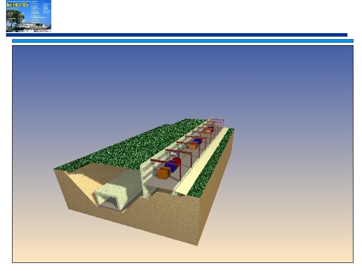
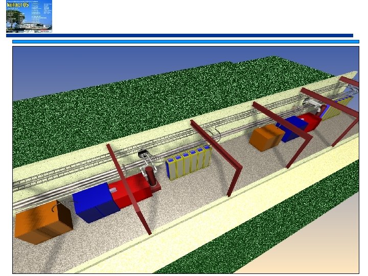
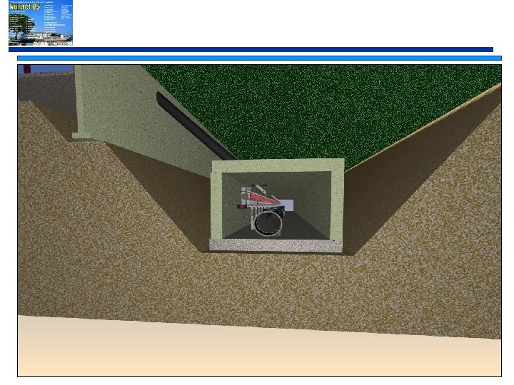
 Gallery and Tunnel Cross Section Main Injector Depth & Shielding • Two-Tunnel Layout • Surface Klystron Gallery • Cross-section similar to SNS tunnel All Floors in plane of Main Injector
") Other Possible Physics with Intense Proton Sources • Rare decays (window for new physics) Intense Kaon beams! e. g. BR (KL → p o n n ) • Muon physics (with intense muon beams) – Rare muon decays, Search for lepton flavor violation : m → eg or m → 3 e – Muon EDM, CP violation – Precision measurements: g-2 (statistics limits understanding systematics) • Neutrino Factories • Anti-Proton Physics – Fermilab will have by far the worlds most intense source of antiproton. What should we do with it ? • Long pulse spallation neutron source, etc…
Other Possible Physics with Intense Proton Sources • Rare decays (window for new physics) Intense Kaon beams! e. g. BR (KL → p o n n ) • Muon physics (with intense muon beams) – Rare muon decays, Search for lepton flavor violation : m → eg or m → 3 e – Muon EDM, CP violation – Precision measurements: g-2 (statistics limits understanding systematics) • Neutrino Factories • Anti-Proton Physics – Fermilab will have by far the worlds most intense source of antiproton. What should we do with it ? • Long pulse spallation neutron source, etc…
 The FY 06 Budget Shake-Down • Cancellation of BTe. V • Tevatron shuts off for good in ~2009 • B-factory operations cease ~2008 No collider physics in US after ~2009 • Consequences for Nuclear Physics worse: – Choice of shutting down RHIC or CEBAF • See NSC charge letter: http: //usnuclearscience. org – RIA project on indefinite hold
 Spectrum of Reactions to the FY 06 Budget at FNAL Reaction from the “Blue States”: “ The FY 06 budget alows us to use the money freed up by the cancellation of BTe. V and Tevatron operations and B-Factory operations to push for the Linear Collider as fast as possible” (the SCRF Proton Driver is somewhere in the center … ) Reaction from the “Red States”: “ The FY 06 budget proves the Linear Collider is not going to happen in our lifetimes, and we should put our money into an affordable neutrino program with big detectors and the cheapest possible accelerator upgrades to get more protons as soon as possible” There are good people on both sides of this debate, and it is impossible to prove either one of these reactions is wrong…
 The SCRF Proton Driver Occupies the Middle Ground in this Debate • Build a ~$500 M Neutrino program Facility with “guaranteed physics payoff” on a medium-term time scale. • Obtain, as byproduct, an “ILC Collider Test Facility” (the Proton Driver) to show that we know what it costs to build the US – ILC – Probably pays for itself in contingency reduction alone • Put the US-World HEP community in a position to make a fast start to the ILC when LHC physics and international politics solidifies: “go” in 2010 funds in 2013 – Use the Proton Driver project to prototype a multi-lab collaboration capable of building the US-ILC.
 A Budget Profile that Might be Successfully Defended • FY 08 - FY 12: ~$100 M/yr PD/ILC facility – Mostly redirected, hope for some new money – Neutrino detector initiatives through both redirection and collaboration • FY 13 -- start of US-ILC construction – U. S. $500 M/yr not unreasonable following successful completion of $500 M SCRF Proton Driver project – Number of years depends on progress on ILC cost reduction.
 Conclusions • Intense Proton Sources are essential for a timely progress on the front of n Physics • The US HEP community is proposing two implementations to achieve ~1 MW proton beams on a ~5 year timescale. • Both the AGS and FNAL PD proposals are building on past experience and existing facilities or proven technologies to be technically defendable. The FNAL proposal also exploits a critical and important synergy with the ILC Project. • The next ~2 years will be critical for the PD Proposals in the US.
 Support Slides
 Fermilab Long Range Plan • In May of 2004 Fermilab completed a Long Range Planning exercise • The report is available at: http: //www. fnal. gov/directorate/Longrange/Long_range_planning. html • The vision expressed in that report is that Fermilab will remain the primary site for accelerator-based particle physics in the U. S. regardless of the siting or schedule for the International Linear Collider – If successful as host to a linear collider Fermilab would be established as a world center for physics at the energy frontier for many decades. – If a linear collider were constructed elsewhere, or delayed, Fermilab would strive to become a world center in neutrino physics, based on new multi-MW Proton Source (AKA Proton Driver) – One possible scenario is that an SCRF Linac based Proton Driver is built at Fermilab as a first step towards a U. S. hosted International Linear Collider Fermilab is pursuing Linear Collider and Proton Driver R&D in parallel. The recent ITRP decision to use cold technology for the International Linear Collider allows close alignment of these paths.
 1. Main Injector Beam • Main Injector Proton Load – 1. 5 E 14 (25 u. C) (same as SNS) – 2. 3 Amps circulating current – 5 x Main Injector Design • Main Injector Cycle Time = 1. 5 Seconds – No upgrade to MI Ramp Rate assumed (yet) – Linac Easily Supports Faster MI Cycles in Future STRATEGY: • Reach 2 MW in MI by 5 x increase of Beam current, • Upgrades past 2 MW possible by increasing cycle rate Fast injection from Linac makes this possible Fermilab G. W. Foster – Proton Driver Director’s Review
 2. Linac Pulse Parameters Comparison with Other SRF Linacs Fermilab G. W. Foster – Proton Driver Director’s Review
: 1. 325") 5. Spokes-to-Elliptical Transition 1. Preserving two technical options (110 -400 Me. V): 1. 325 MHz triple-spoke Resonators 2. 1300 MHz Elliptical Cavities 2. (BASELINE) The tradeoffs have been extensively discussed for the Rare Isotope Accelerator (RIA). 3. Our Decision Will be based on: 1. Accelerator Physics 2. Cost 3. Collaboration Fermilab G. W. Foster – Proton Driver Director’s Review
5. Spokes-to-Elliptical Transition 1. Preserving two technical options (110 -400 Me. V): 1. 325 MHz triple-spoke Resonators 2. 1300 MHz Elliptical Cavities 2. (BASELINE) The tradeoffs have been extensively discussed for the Rare Isotope Accelerator (RIA). 3. Our Decision Will be based on: 1. Accelerator Physics 2. Cost 3. Collaboration Fermilab G. W. Foster – Proton Driver Director’s Review
 MEBT • • • In our MEBT we have an axisymmetric beam after RFQ. 4 SC solenoids are used for focusing and matching 2 RT TSR are used as the rebunchers One chopper This is conceptual design. The detailed design is still ahead. SC solenoid MEBT RT SR TRACK simulation
 MEBT SC Solenoids • First Prototype be Oct. ‘ 05 Stresses at 0 A, 4 K
 MORE INFORMATION • Project site: http: //protondriver. fnal. gov • Soon: Physics and Machine “CD-0” Documents • Recent Director’s Review: http: //protondriver. fnal. gov/PDrev 15 Mar 05. htm • Upcoming Workshop: http: //www. niu. edu/clasep/HPSLconf/