
Презентация Zadar ELMAR 2004 Presentation Vejrazka


zadar_elmar_2004_presentation_vejrazka.ppt
- Размер: 11 Mегабайта
- Количество слайдов: 73
Описание презентации Презентация Zadar ELMAR 2004 Presentation Vejrazka по слайдам
PRESENT SATELLITE RADIO NAVIGATION SYSTEMS, THEIR PERFORMANCE AND USER RECEIVER CONCEPTS František Vejražka , Pavel Kovář, Libor Seidl, Petr Kačmařík, Josef Špaček, Pavel Puričer Department of Radio Engineering Czech Technical University in Prague Czech Republic
Abstract This contribution gives an overview of present and future navigation systems and their augmentations such as GPS, GLONASS, GALILEO, WAAS, EGNOS, MSAT, QZSS, BEIDOU, GAGAN. Performance of the systems depends on their technical parameters. We will try to evaluate these and to present our opinion on their advantages for different applications and in various situations (reception of weak signals suffering from great attenuation under vegetation canopy, in urban canyons, influence of reflections and multipath). The last part of the contribution deals with an application of software radio technology for user receiver design and results obtained from experiments with different algorithms of processing the satellite navigation systems signals.
Terminology Satellite (Radio) Navigation Systems ~ Radio Determination Satellite Systems ~ S ystems for radio position determination using satellites
Satellite Navigation System s Historical Satellite Navigation Systems (not realized) • 601 • TIMATION • . . . • GEOSTAR • REXSTARGPS — NAVSTAR
Satellite Navigation System s Past Satellite Navigation Systems • NNSS — Transit • Tsikad GPS — NAVSTAR realized but cancelled
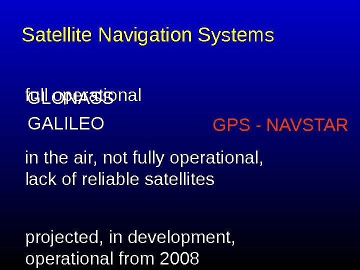
full operational. Satellite Navigation System s GLONASS GPS — NAVSTAR GALILEO in the air, not fully operational, lack of reliable satellites projected, in development, operational from
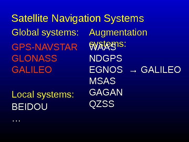
Satellite Navigation System s GPS-NAVSTAR GLONASS GALILEO Global systems: Local systems: Augmentation systems: BEIDOU … WAAS NDGPS EGNOS MSAS GAGAN QZSS → GALILEO
Principles of Satellite Navigation Systems • Doppler systems • Ranging systems
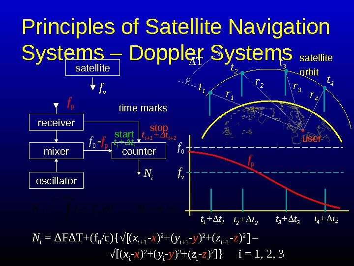
Principles of Satellite Navigation Systems – Doppler Systems satellite f v t 1 + t 1 t 2 + t 2 t 3 + t 3 t 4 + t 4 f p f 0 crtdtffii tt tt pi ii ii /Δ )(N 11Δ Δ 0 receiver f p mixer oscillator f 0 — f p N icountertime marks start t i + t i stop t i+1 + t i+1 N i = Δ F Δ T+(f 0 /c) { √ [ ( x i+1 — x ) 2 +( y i+1 — y ) 2 +( z i+1 — z ) 2 ] – √ [ ( x i — x ) 2 +( y i — y ) 2 +( z i — z ) 2 ] } i = 1, 2, 3 satellite orbit T t 2 t 3 t 1 t 4 r 1 r 2 r 3 r 4 user
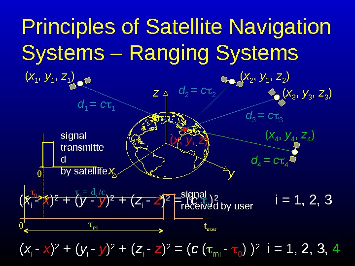
Principles of Satellite Navigation Systems – Ranging Systems ( x 1 , y 1 , z 1 ) ( x 2 , y 2 , z 2 ) ( x 3 , y 3 , z 3 ) ( x 4 , y 4 , z 4 ) d 4 = c 4 ( x i — x ) 2 + ( y i — y ) 2 + ( z i — z ) 2 = ( c ( mi — 0 ) ) 2 i = 1, 2, 3, 4( x , y , z ) x z y 0 mi 0 i = d i /c 0 signal transmitte d by satellite t usersignal received by userd 1 = c 1 d 2 = c 2 d 3 = c 3 ( x i — x ) 2 + ( y i — y ) 2 + ( z i — z ) 2 = ( c i ) 2 i = 1, 2,
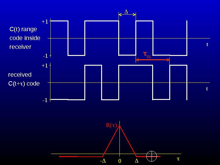
+1 -1 t m received C(t+ ) code +1 -1 t C(t) range code inside receiver — 0 R( )
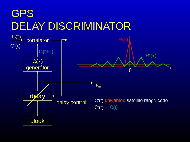
GPS DELAY DIS C RIMIN ATOR correlator C( ) generátor delay clock delay control. C(t+ )C(t) 0 R( ) m. C * (t) unwanted satellite range code C * (t) C(t) R * ( )
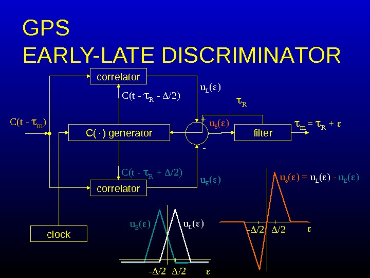
GPS EARLY-LATE DIS C RIMIN A TOR correlator C( ) generator clock m = R + correlator filter. C(t — m ) + — C(t — R + /2) u E ( )C(t — R — /2) u L ( ) /2 — /2 u L ( ) /2 — /2 u ( ) = u L ( ) — u E ( ) u ( ) R
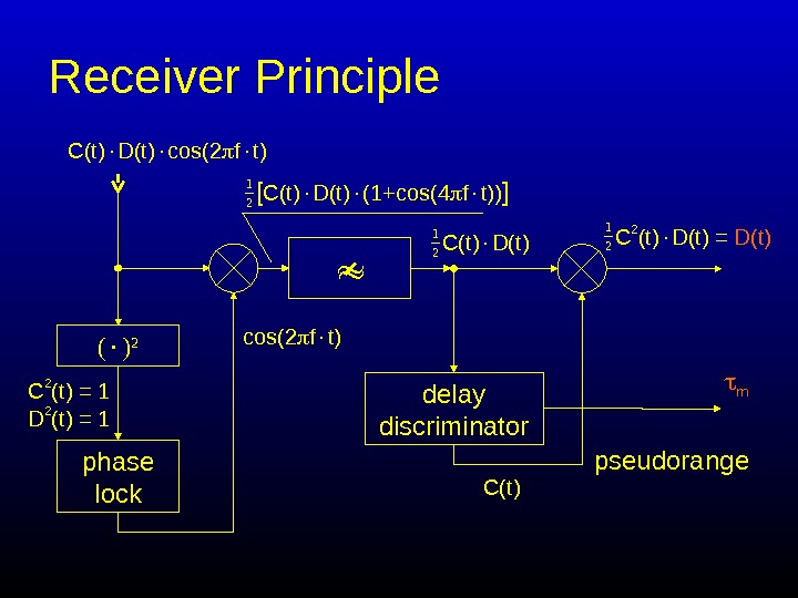
Receiver Principle ( ) 2 phase lock m pseudorangedelay discriminator. C(t) D(t) cos(2 f t) [ C(t) D(t) (1+cos(4 f t)) ]1 2 cos(2 f t) C 2 (t) = 1 D 2 (t) = 1 C(t) D(t) 1 2 C(t) C 2 (t) D(t) = D(t)
Systems Parameters (Properties) We will deal with systems: • GPS – NAVSTAR • GLONASS • GALILEO
GPS — NAVSTAR
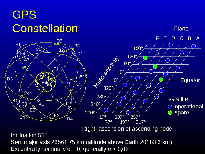
GPS Constellation 0° 40° 80° 120° 160° 320° 280° 240° 200° 17° 77° 137° 197° 257° 317° satellite operational spare Equator Right ascension of ascending node. M ean anom aly F E D B APlane Inclination 55 ° Semimajor axis 26561. 75 km (altitude above Earth 20183, 6 km) Excentricity nominally e = 0, generally e < 0,
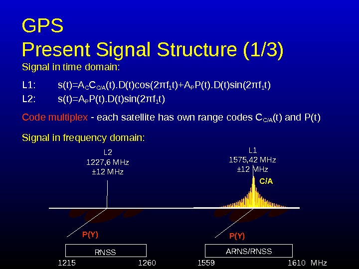
GPS Present Signal Structure (1/3) Signal in time domain: L 1: s(t)=A C C C/A (t). D(t)cos(2 πf 1 t)+A P P(t). D(t)sin(2πf 1 t) L 2: s(t)= A P P(t). D(t)sin(2πf 1 t) Code multiplex — each satellite has own range codes C C/A (t) and P(t) Signal in frequency domain: L 2 1227, 6 MHz ± 12 MHz L 1 1575, 42 MHz ± 12 MHz ARNS/RNSS 1260 1559 1610 C/A P(Y) MHz 1215 RNSS
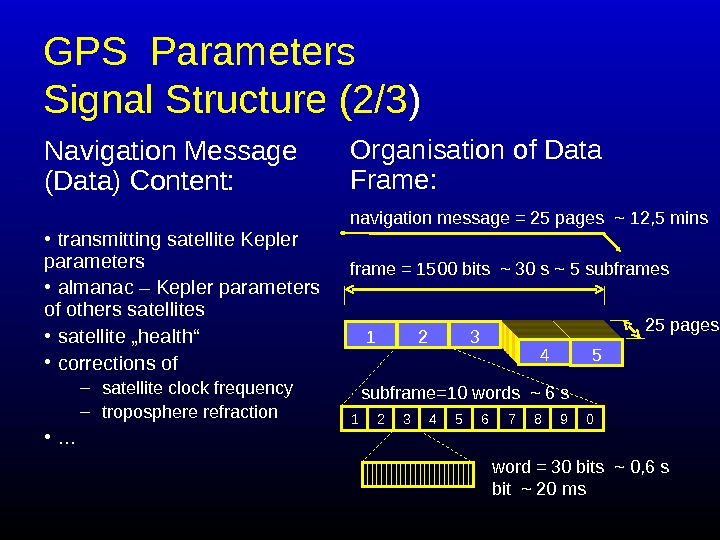
GPS Parameters Signal Structure (2/3 ) Navigation Message (Data) Content: • transmitting satellite Kepler parameters • almanac – Kepler parameters of others satellites • satellite „health“ • corrections of – satellite clock frequency – troposphere refraction • … Organisation of Data Frame: 5432 1 navigation message = 25 pages ~ 12, 5 mins frame = 1500 bits ~ 30 s ~ 5 subframes 25 pages 0987654321 subframe=10 words ~ 6 s word = 30 bits ~ 0, 6 s bit ~ 20 ms
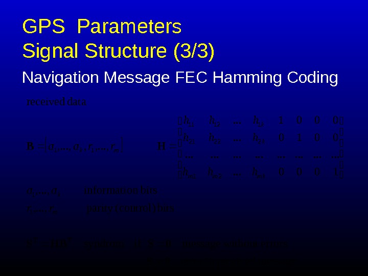
GPS Parameters Signal Structure (3/3) Navigation Message FEC Hamming Coding message receivedin errors without message ifsyndrom bits (control)parity , . . . , bitsn informatio, . . . , 1000. . . . 0010. . . 0001. . . , , , . . . , data received 1 1 21 22221 11211 11 0 S 0 SHBS HB TT m k mkmm kk mk rr aa hhh hhh rraa
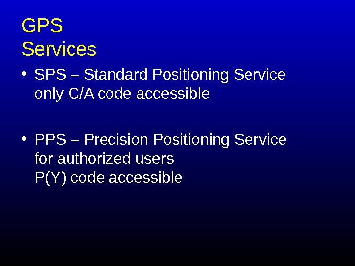
GPS Services • SPS – Standard Positioning Service only C/A code accessible • PPS – Precision Positioning Service for authorized users P(Y) code accessible
GLONASS
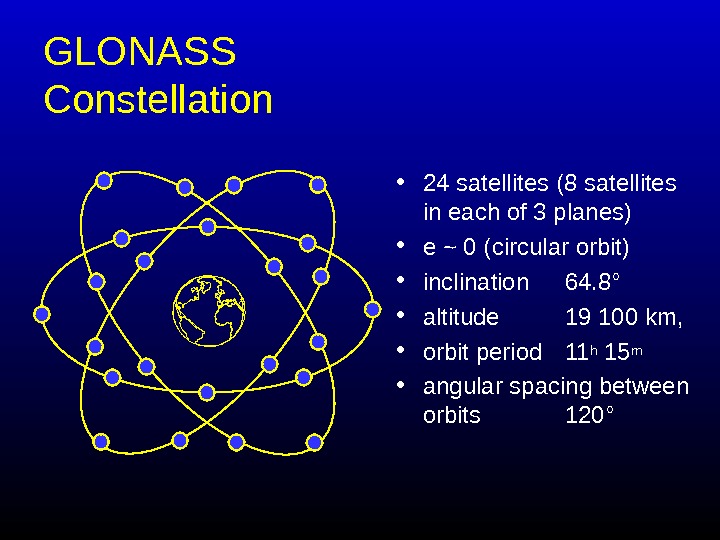
GLONASS Constellation • 24 satellites (8 satellites in each of 3 planes) • e ~ 0 ( circular orbit ) • inclination 64. 8° • altitude 19 100 km, • orbit period 11 h 15 m • angular spacing between orbits 120°
GLONASS Signal Structure • Frequencies: – L 1: fj = 1602 + 9 j/16 – L 2: f i = 1246 + 7 i/16 [MHz] • Modulation: – Navigation message – Pseudorandom ranging code • Sequence of maximum length • Period 1 msec • Bit rate 511 kb/s – 100 Hz auxiliary meander sequence – Manchester code
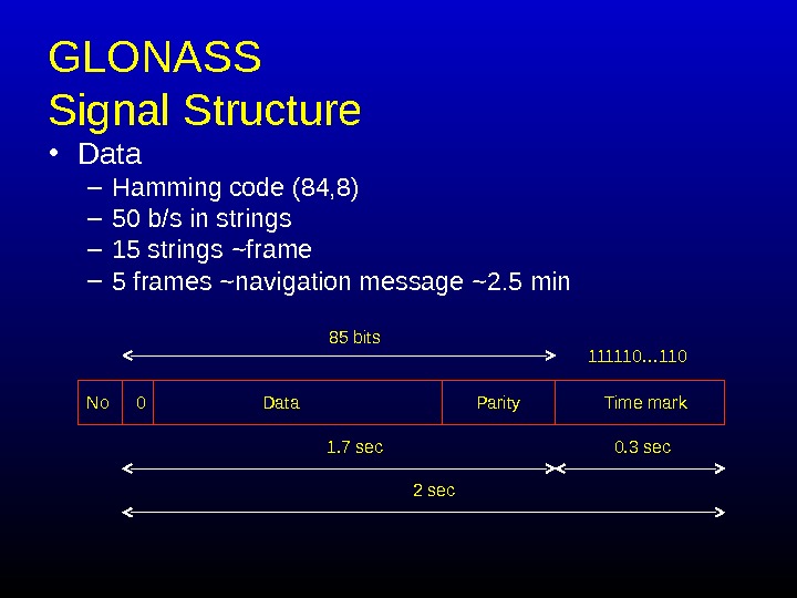
GLONASS Signal Structure • Data – Hamming code (84, 8) – 50 b/s in strings – 15 strings ~ frame – 5 frames ~ navigation message ~ 2. 5 min No Data Parity Time mark 2 sec 0 85 bits 111110… 110 1. 7 sec 0. 3 sec
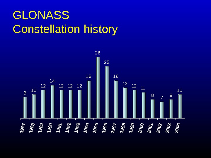
GLONASS Constellation history
GALILEO
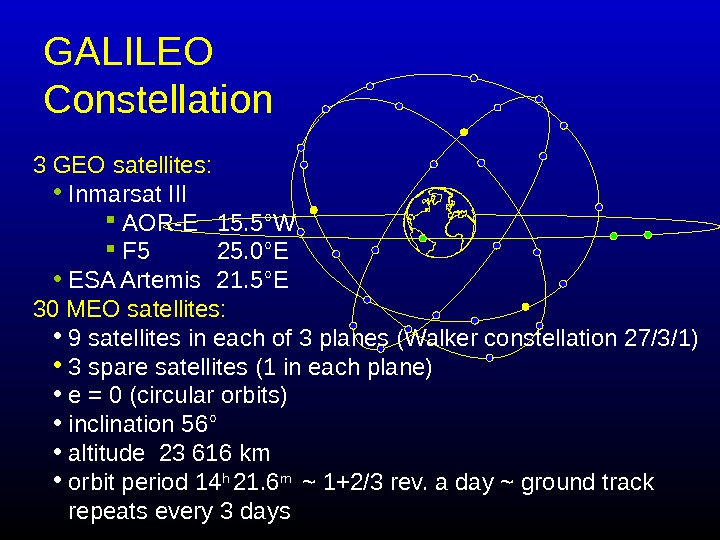
GALILEO Constellation 3 GEO satellites: • Inmarsat III AOR-E 1 5. 5 °W F 5 2 5. 0 ° E • ESA Artemis 2 1. 5 °E 30 MEO satellites: • 9 satellites in each of 3 planes (Walker constellation 27/3/1) • 3 spare satellites (1 in each plane) • e = 0 (circular orbits) • inclination 56 ° • altitude 23 616 km • orbit period 14 h 21. 6 m ~ 1+2/3 rev. a day ~ ground track repeats every 3 days
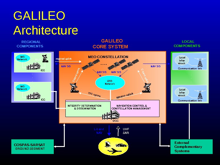
GALILEO Architecture USER SEGMENT IMS GALILEO CORE SYSTEM TTC uplink GCC L-band NAV UHF SAR…. REGIONAL COMPONENTS LOCAL COMPONENTS COSPAS-SARSAT GROUND SEGMENT MEO CONSTELLATION External Complementary Systems C-band uplinkregional uplink S-band uplink GSS Network ICC IMS Network IULS Communication link Local Infra- struct. . . NAV SIS NAV SIS INTEGRITY DETERMINATION & DISSEMINATION NAVIGATION CONTROL & CONSTELLATION MANAGEMENT Mission uplink
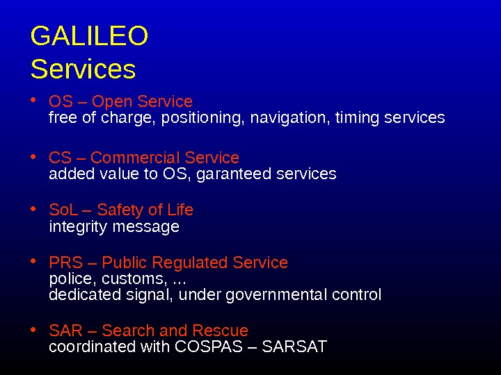
GALILEO Services • OS – Open Service free of charge, positioning, navigation, timing services • CS – Commercial Service added value to OS, garanteed services • So. L – Safety of Life integrity message • PRS – Public Regulated Service police, customs, . . . dedicated signal, under governmental control • SAR – Search and Rescue coordinated with COSPAS – SARSAT
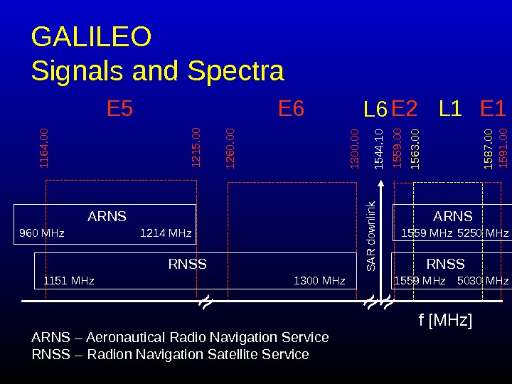
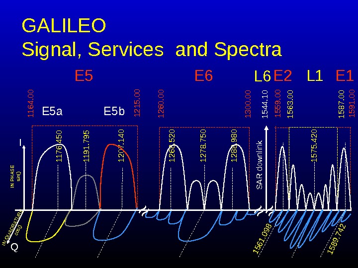
GALILEO Signals and Spectra 1164. 00 1215. 00 E 5 1260. 00 1300. 00 E 6 1563. 00 1587. 00 L 1 1559. 00 E 2 1591. 00 E 1 1544. 10 S A R dow nlink L 6 ≈≈≈ f [MHz]ARNS 960 MHz 1214 MHz 1151 MHz 1300 MHz. RNSS 1559 MHz 5250 MHz 1559 MHz 5030 MHz. RNSS ARNS – Aeronautical Radio Navigation Service RNSS – Radion Navigation Satellite Service
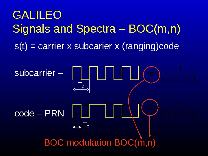
GALILEO Signals and Spectra – BOC(m, n) s(t) = carrier x subcarier x (ranging)code subcarrier – code – PRN T S T C C 6 S 6 T 1, 023. 10 1 n T 1, 023. 10 1 m BOC modulation BOC(m, n)
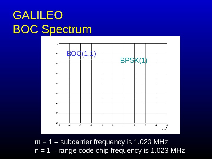
GALILEO BOC Spectrum 54321012345 x 106 40 35 30 25 20 15 10 5 0 BOC(1, 1) BPSK(1) m = 1 – subcarrier frequency is 1. 023 MHz n = 1 – range code chip frequency is 1. 023 MHz
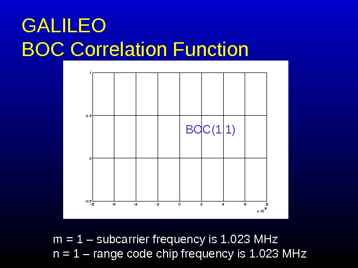
GALILEO BOC Correlation Function 864202468 x 106 0. 5 0 0. 5 1 BOC(1, 1) m = 1 – subcarrier frequency is 1. 023 MHz n = 1 – range code chip frequency is 1. 023 MHz
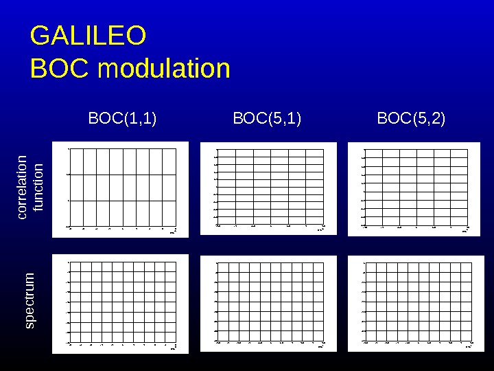
GALILEO BOC modulation 2. 521. 510. 500. 511. 522. 5 x 10740 35 30 25 20 15 10 5 0 2. 52 1. 510. 500. 511. 522. 5 x 10740 35 30 25 20 15 10 5 0 54 3 21012345 x 106 40 35 30 25 20 15 10 5 0 864202468 x 1060. 5 0 0. 5 1 1. 5 10. 500. 511. 5 x 10 6 1 0. 8 0. 6 0. 4 0. 2 0. 4 0. 6 0. 8 1 1. 5 1 0. 500. 511. 5 x 10⁶ 0. 8 0. 6 0. 4 0. 2 0. 4 0. 6 0. 8 1 BOC(1, 1) BOC(5, 2) co rre la tio n fu n ctio n s p e ctru m
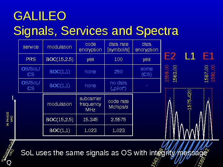
GALILEO Signals, Services and Spectra I QIN PHASE sin() IN QUADRATURE cos() 1575. 420 1561. 098 1589. 742 1559. 00 1591. 00 L 1 1563. 00 1587. 00 E 2 E 1 service modulation code encryption data rate [ symbol/s ] data encryption PRS BOC(15, 2. 5) yes 100 yes OS /So. L/ CS BOC(1, 1) none 250 some (CS) OS/So. L/ CS BOC(1, 1) none no data („pilot“) — modulation subcarrier frequency MHz code rate Mchips/s BOC(15, 2. 5) 15. 345 2. 5575 BOC(1, 1) 1. 023 So. L uses the same signals as OS with integrity message
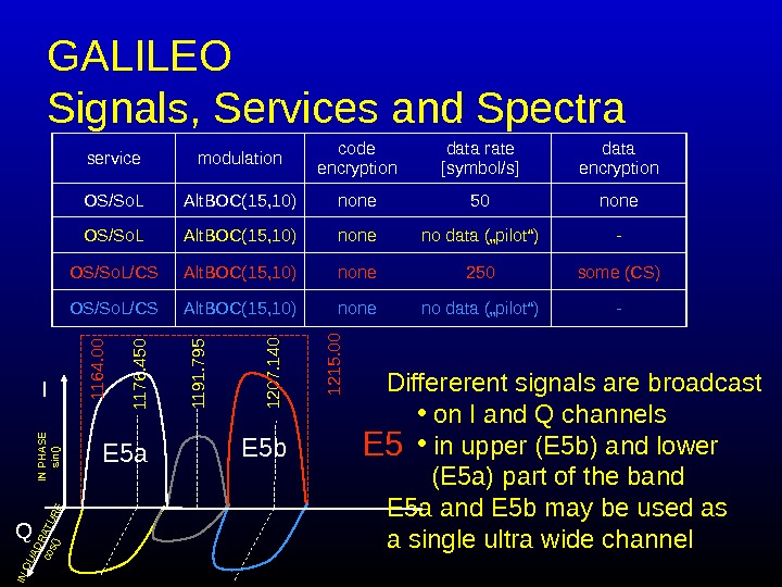
GALILEO Signals, Services and Spectra 1176. 450 1207. 140 1191. 795 E 5 a E 5 b 1164. 00 1215. 00 E 5 I Q IN PHASE sin() IN QUADRATURE cos() service modulation code encryption data rate [ symbol/s ] data encryption OS/So. L Alt. BOC(15, 10) none 50 none OS/So. L Alt. BOC(15, 10) none no data („pilot“) — OS /So. L/CS Alt. BOC(15, 10) none 250 some (CS) OS/So. L/CS Alt. BOC(15, 10) none no data („pilot“) — Differerent signals are broadcast • on I and Q channels • in upper (E 5 b) and lower (E 5 a) part of the band E 5 a and E 5 b may be used as a single ultra wide channel
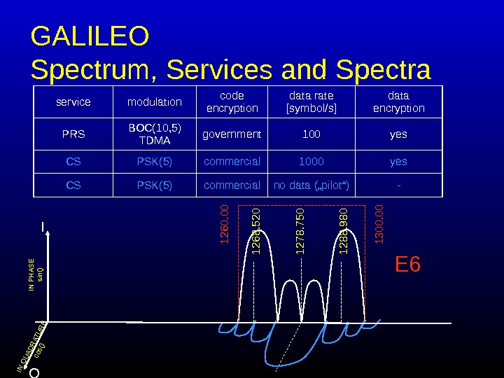
GALILEO Spectrum , Services and Spectra 1278. 750 1268. 520 1288. 980 1260. 00 1300. 00 E 6 I Q IN PHASE sin() IN QUADRATURE cos() service modulation code encryption data rate [symbol/s] data encryption PRS BOC(10, 5) TDMA government 100 yes CS PSK(5) commercial 1000 yes CS PSK(5) commercial no data („pilot“) —
GALILEO Signal, Services and Spectr a I Q 1176. 450 1207. 140 1278. 750 1575. 420 1544. 10 1191. 795 1268. 520 1288. 980 IN PHASE sin() IN QUADRATURE cos() 1561. 098 1589. 742 1164. 00 1215. 00 1260. 00 1300. 00 1559. 00 1591. 00 E 5 E 6 L 1 1563. 00 1587. 00 E 2 E 1 E 5 a E 5 b S A R dow nlink L 6 ≈≈≈
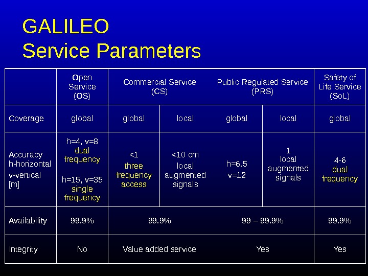
GALILEO Service Parameters Open Service (OS) Commercial Service (CS) Public Regulated Service (PRS) Safety of Life Service (So. L) Coverage global local global Accuracy h-horizontal v-vertical [m] h=4, v=8 dual frequency h=15, v=35 single frequency <1 three frequency access <10 cm local augmented signals h=6. 5 v=12 1 local augmented signals 4 -6 dual frequency Availability 99. 9% 99 – 99. 9% Integrity No Value added service Yes
BEIDOU
BEIDOU „ China‘s „Beidou“ navigation system is a regional positioning system mainly covering the country and its neighbouring areas, thus making vertical positioning impossible and limiting the number of users. “ • 3 geostationary satellites • circular orbits
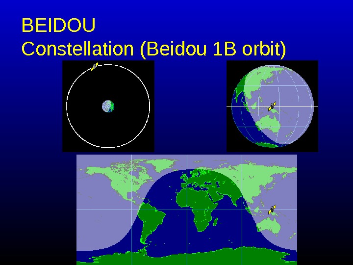
BEIDOU Constellation (Beidou 1 B orbit)
Augmentations
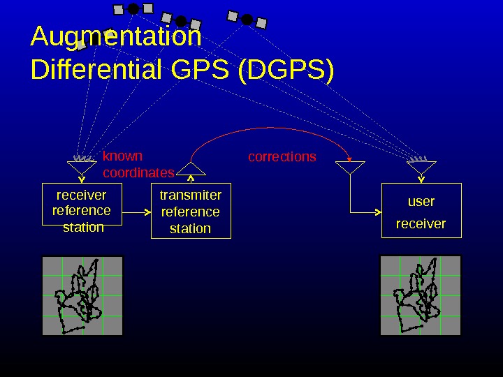
transmiter reference station correctionsknown coordinates receiver. Augmentation Differential GPS (DGPS) reference station user
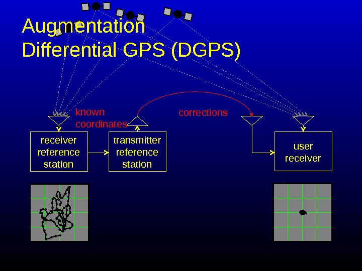
transmitter reference station correctionsknown coordinates receiver reference station user receiver. Augmentation Differential GPS (DGPS)
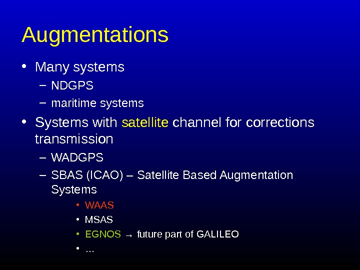
Augmentation s • Many systems – NDGPS – maritime systems • Systems with satellite channel for corrections transmission – WADGPS – SBAS (ICAO) – Satellite Based Augmentation Systems • WAAS • MSAS • EGNOS → future part of GALILEO • …
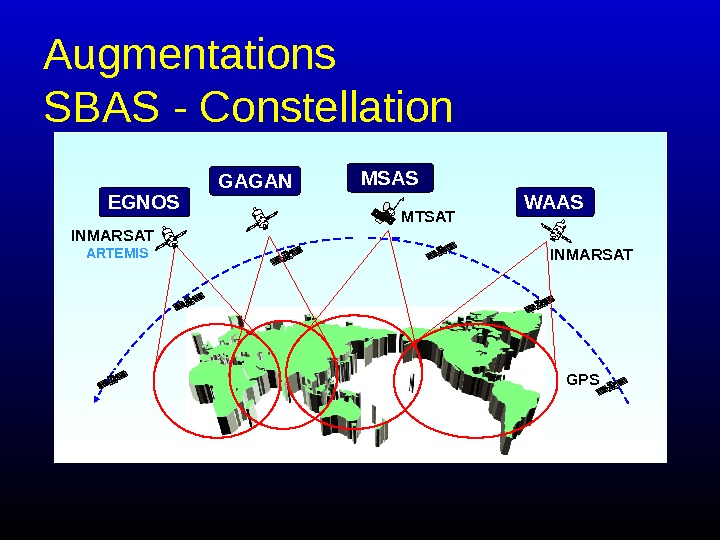
Augmentations SBAS — Constellation ARTEMIS GPSMTSAT INMARSATEGNOS MSAS WAASGAGAN
Augmentation s SBAS — signals Similar to SATNAV systems signals
Augmentation QZSS
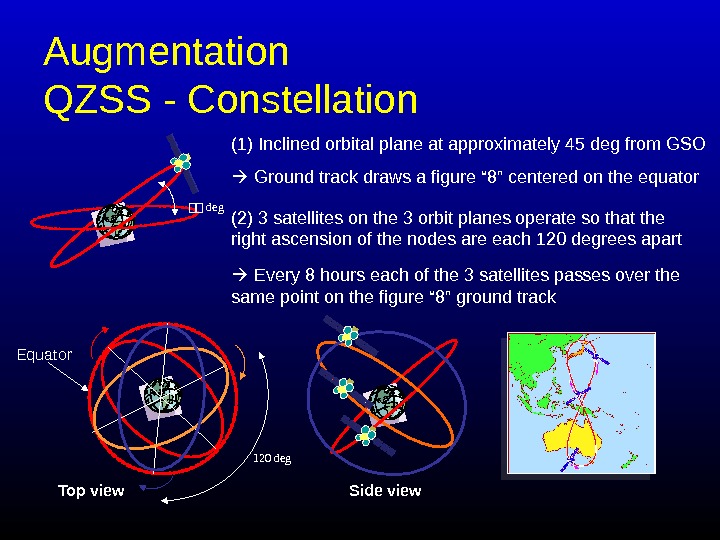
Augmentation QZSS — Constellation (1) Inclined orbital plane at approximately 45 deg from GSO Ground track draws a figure “ 8” centered on the equator 44 deg Side view. Equator 120 deg Top view (2) 3 satellites on the 3 orbit planes operate so that the right ascension of the nodes are each 120 degrees apart Every 8 hours each of the 3 satellites passes over the same point on the figure “ 8” ground track
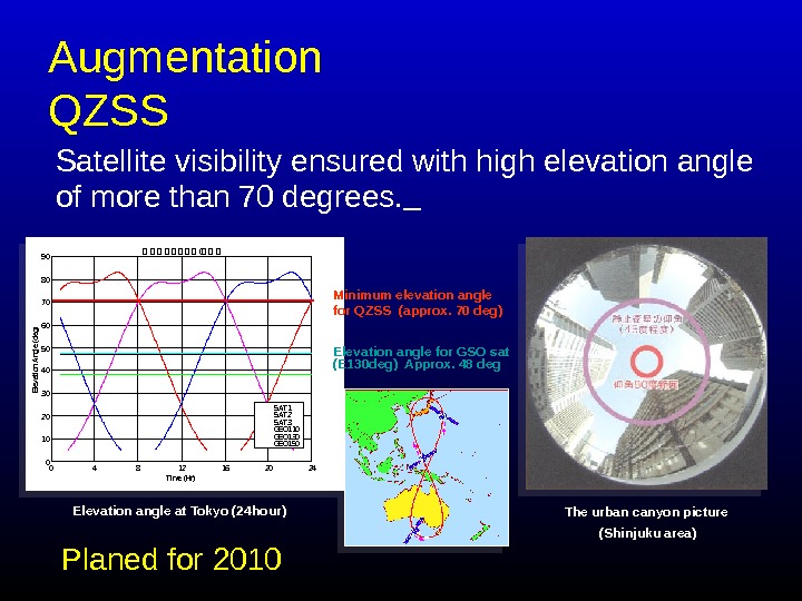
Augmentation QZSS Satellite visibility ensured with high elevation angle of more than 70 degrees. The urban canyon picture (Shinjuku area)0 4 8 12 16 20 240102030405060708090 4 4 4 4 (4 4 4 Time (Hr)Elevation Angle (deg) SAT 1 SAT 2 SAT 3 GEO 110 GEO 130 GEO 150 Elevation angle at Tokyo (24 hour) Minimum elevation angle for QZSS (approx. 70 deg) Elevation angle for GSO sat (E 130 deg) Approx. 48 deg Planed for
MODERNISATION GPS
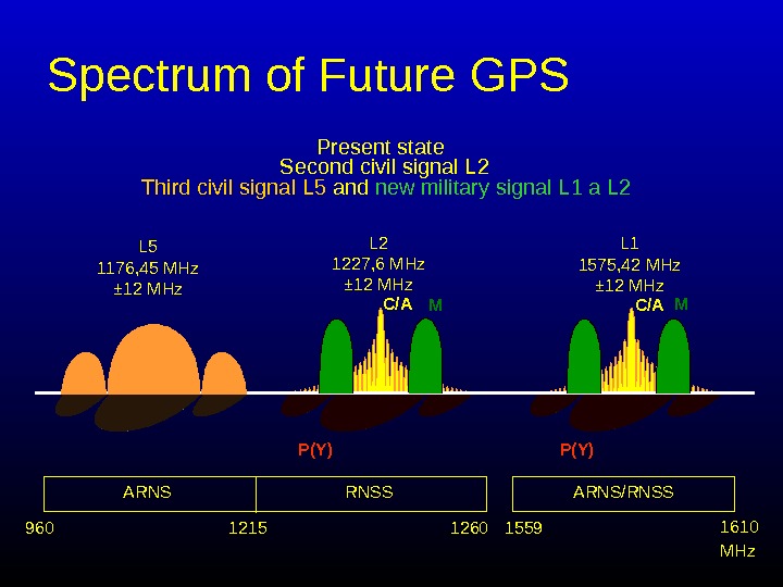
Spectrum of Future GPS Present state Second civil signal L 2 C/AL 2 1227, 6 MHz ± 12 MHz L 1 1575, 42 MHz ± 12 MHz ARNS RNSS ARNS/RNSS 960 1215 1260 1559 1610 C/A P(Y)L 5 1176, 45 MHz ± 12 MHz Third civil signal L 5 and new military signal L 1 a L 2 M M MHz
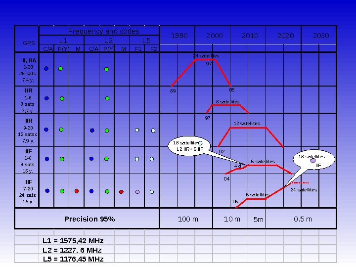
C/A P(Y) M F 1 F 2 II, IIA 1 -28 28 sats 7, 4 y. IIR 1 -8 8 sats 7, 9 y. IIR 9 -20 12 satsc 7, 9 y. IIF 1 -6 6 sats 15 y. IIF 7 -30 24 sats 15 y. 5 m L 1 = 1575, 42 MHz L 2 = 1227, 6 MHz L 5 = 1176, 45 MHz. GPS 1990 2000 2010 2020 2030 L 1 L 2 L 5 Frequency and codes 10 m 0. 5 m 100 m. Precision 95% 24 satellites 89 97 05 97 8 satellites 12 satellites 02 4 d. 6 satellites 04 06 6 satellites 24 satellites 18 satellites 12 IIR+ 6 IIF 18 satellites II
Comparison of Systems
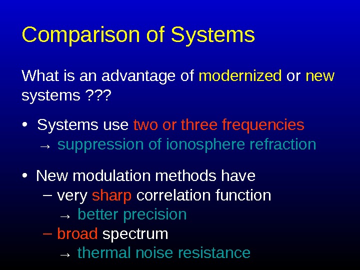
Comparison of Systems What is an advantage of modernized or new systems ? ? ? • Systems use two or three frequencies → suppression of ionosphere refraction • New modulation methods have – very sharp correlation function → better precision – broad spectrum → thermal noise resistance
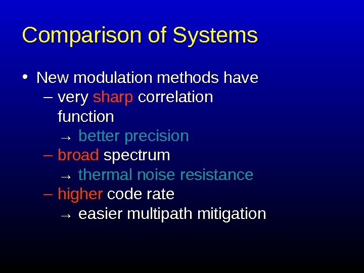
Comparison of Systems • New modulation methods have – very sharp correlation function → better precision – broad spectrum → thermal noise resistance – higher code rate → easier multipath mitigation
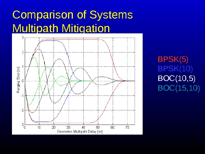
Comparison of Systems Multipath Mitigation BPSK(5) BPSK(10) BOC(10, 5) BOC(15, 10)
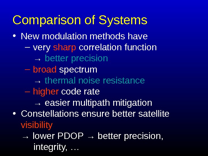
Comparison of Systems • New modulation methods have – very sharp correlation function → better precision – broad spectrum → thermal noise resistance – higher code rate → easier multipath mitigation • Constellations ensure better satellite visibility → lower PDOP → better precision, integrity, …
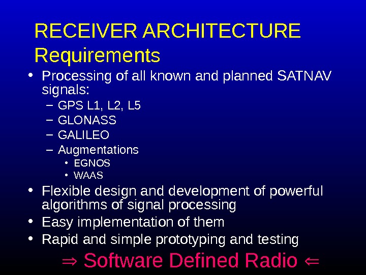
RECEIVER ARCHITECTURE Requirements • Processing of all known and planned SATNAV signals: – GPS L 1, L 2, L 5 – GLONASS – GALILEO – Augmentations • EGNOS • WAAS • Flexible design and development of powerful algorithms of signal processing • Easy implementation of them • Rapid and simple prototyping and testing Software Defined Radio
RECEIVER ARCHITECTURE Requirements Software Defined Radio What processor to use ? ? ? • DSP • FPG
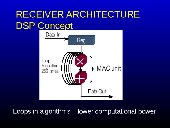
RECEIVER ARCHITECTURE DSP Concept Loops in algorithms – lower computational power
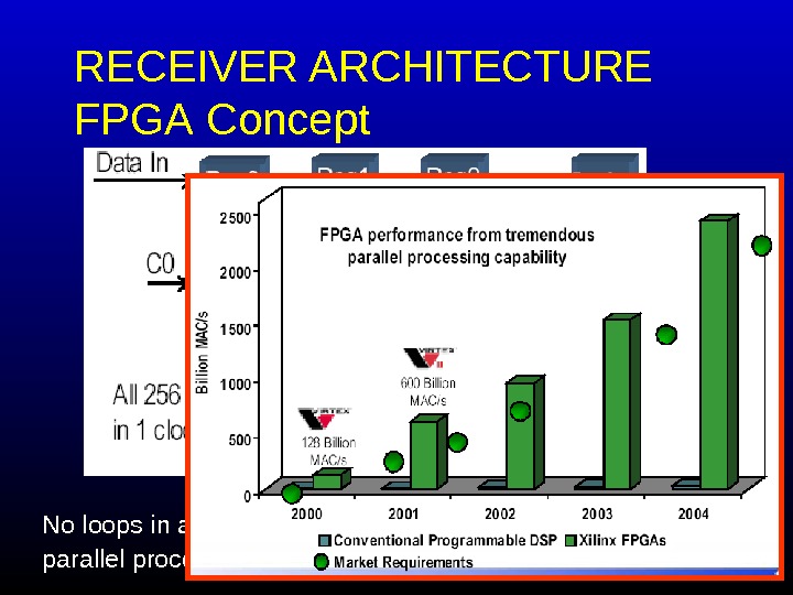
RECEIVER ARCHITECTURE FPGA Concept No loops in algorithms parallel processing → higher computational power
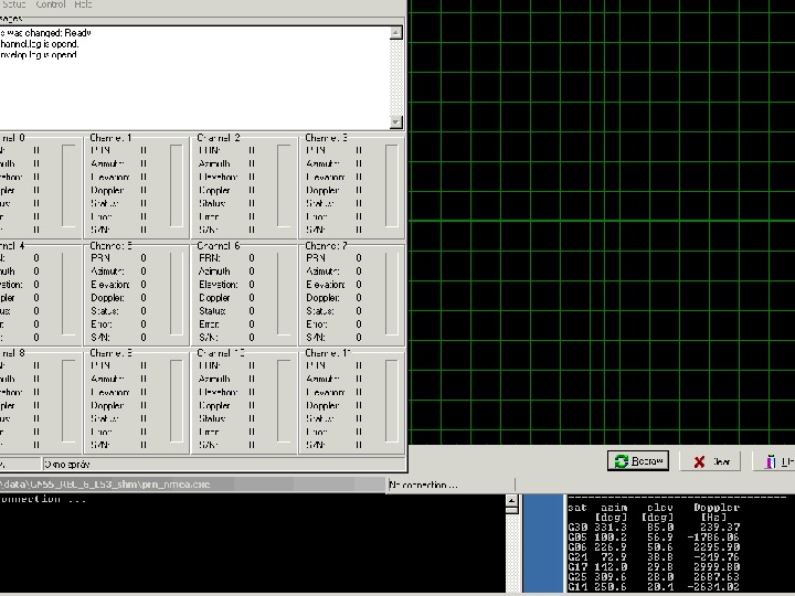
RESULTS at CZECH TECHNICAL UNIVERSITY Experimental receiver
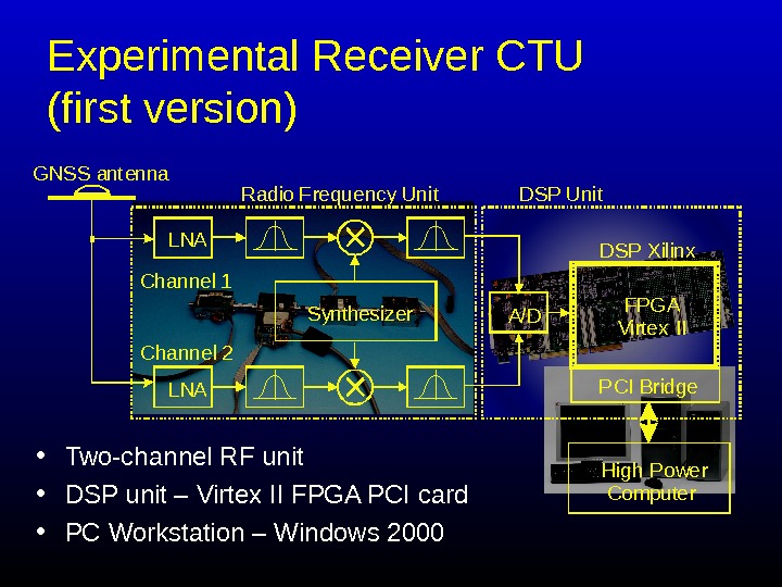
Experimental Receiver CTU (first version) • Two-channel RF unit • DSP unit – Virtex II FPGA PCI card • PC Workstation – Windows 2000 L N A C h a n n e l 1 Cha n n e l 2 L N A A / D F P G A V i r t e x I I P C I B r i d g e. D S P X i l i n x. D S P U n i t. R a d i o F r e q u e n c y U n i t. G N S S a n t e n n a S y n t h esize r H i g h P o w e r C o m p u t e r
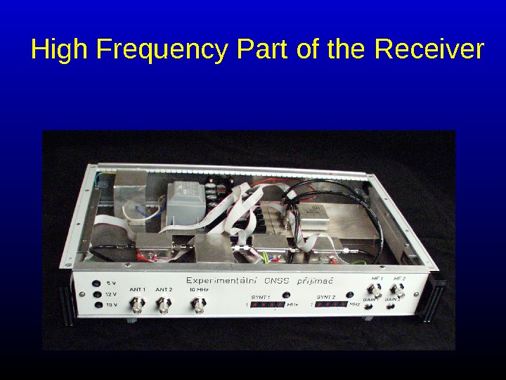
High Frequency Part of the Receiver
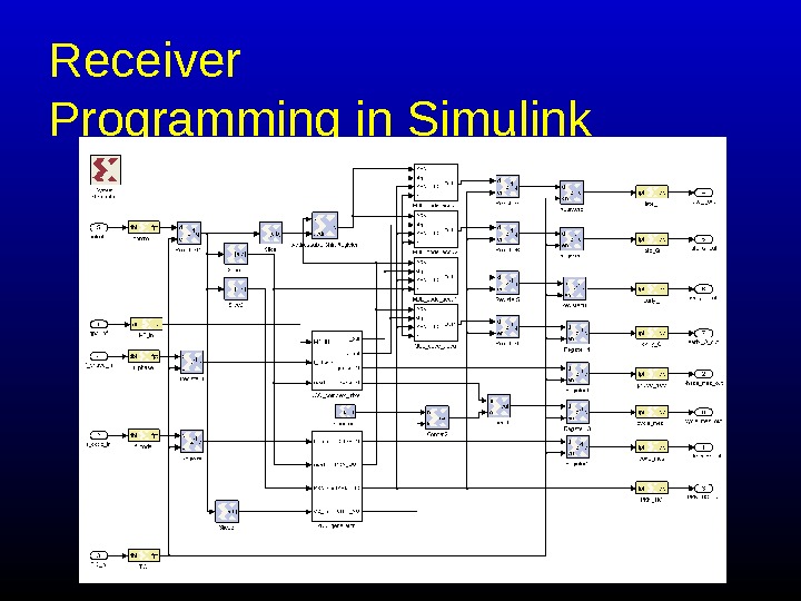
Receiver Programming in Simulink
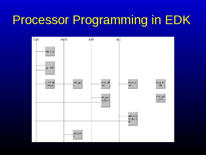
Processor Programming in EDK
Conclusions • Software Radio is prospective technology for multi-systems GNSS receivers, as well as FPGA technology • This technology make possible design of receivers for hard receptions conditions (leaves canopy, urban environment, etc. )
Thank you for your attention. Pavel Kovář & František Vejražka & Libor Seidl Czech Technical University Prague, the Czech Republic http: //radio. feld. cvut. cz/per sonal/vejrazka