
Презентация line broadening


- Размер: 1.1 Mегабайта
- Количество слайдов: 17
Описание презентации Презентация line broadening по слайдам
XRD Line Broadening With effects on Selected Area Diffraction (SAD) Patterns in a TEM MATERIALS SCIENCE && ENGINEERING Anandh Subramaniam & Kantesh Balani Materials Science and Engineering (MSE) Indian Institute of Technology, Kanpur- 208016 Email: anandh@iitk. ac. in, URL: home. iitk. ac. in/~anandh. AN INTRODUCTORY E-BOOKPart of http: //home. iitk. ac. in/~anandh/E-book. htm A Learner’s Guide
Crystallite size and Strain Bragg’s equation assumes: Crystal is perfect and infinite Incident beam is perfectly parallel and monochromatic Actual experimental conditions are different from these leading various kinds of deviations from Bragg’s condition Peaks are not ‘ ’ curves Peaks are broadened (in addition to other possible deviations) There also deviations from the assumptions involved in the generating powder patterns Crystals may not be randomly oriented (textured sample) Peak intensities are altered w. r. t. to that expected In a powder sample if the crystallite size < 0. 5 m there are insufficient number of planes to build up a sharp diffraction pattern peaks are broadened
In the example considered ’ was ‘far away’ (at a larger angular separation) from ( Bragg ) and it was easy to see the destructive interference In other words for incidence angle of ’ the phase difference of is accrued just by traversing one ‘d’. If the angle is just away from the Bragg angle ( Bragg ), then one will have to go deep into the crystal (many ‘d’) to find a plane (belonging to the same parallel set) which will scatter out of phase with this ray (phase difference of ) and hence cause destructive interference If such a plane which scatters out of phase with a off Bragg angle ray is absent (due to finiteness of the crystal) then the ray will not be cancelled and diffraction would be observed just off Bragg angles too line broadening! (i. e. the diffraction peak is not sharp like a -peak in the intensity versus angle plot) This is one source of line broadening. Other sources include: residual strain, instrumental effects, stacking faults etc. When considering constructive and destructive interference we considered the following points:
Instrumental Crystallite size Strain Stacking fault. XRD Line Broadening Other defects Unresolved 1 , 2 peaks Non-monochromaticity of the source (finite width of peak) Imperfect focusing In the vicinity of B the −ve of Bragg’s equation not being satisfied ‘ Residual Strain’ arising from dislocations, coherent precipitates etc. leading to broadening In principle every defect contributes to some broadening. B i B C B S. . . )(SFsci. BBBBFWHMB B S
. . . )(SFsci. BBBBFWHMBThe diffraction peak we see is a result of various broadening ‘mechanisms’ at work Full Width at Half-Maximum (FWHM) is typically used as a measure of the peak ‘width’ XRD Line Broadening
Crystallite size Size > 10 m Spotty ring (no. of grains in the irradiated portion insufficient to produce a ring) Size (10, 0. 5) Smooth continuous ring pattern Size (0. 5, 0. 1) Rings are broadened Size < 0. 1 No ring pattern (irradiated volume too small to produce a diffraction ring pattern & diffraction occurs only at low angles) Spotty ring Rings Broadened Rings. Diffuse 10 m 0. 5 Rings 0. 1 0. 5 In a TEM Selected Area Diffraction (SAD) pattern, with decreasing crystallite size the following effects are observed on the pattern obtained. Line Broadening in SAD patterns in the TEM
Effect of crystallite size on SAD patterns Single crystal “ Spotty” pattern Few crystals in the selected region Schematics Rotation has been shown only along one axis for easy visualization Rotation in along all axes should be considered to ‘simulate’ random orientation
Effect of crystallite size on SAD patterns Ring pattern Broadened Rings Schematics
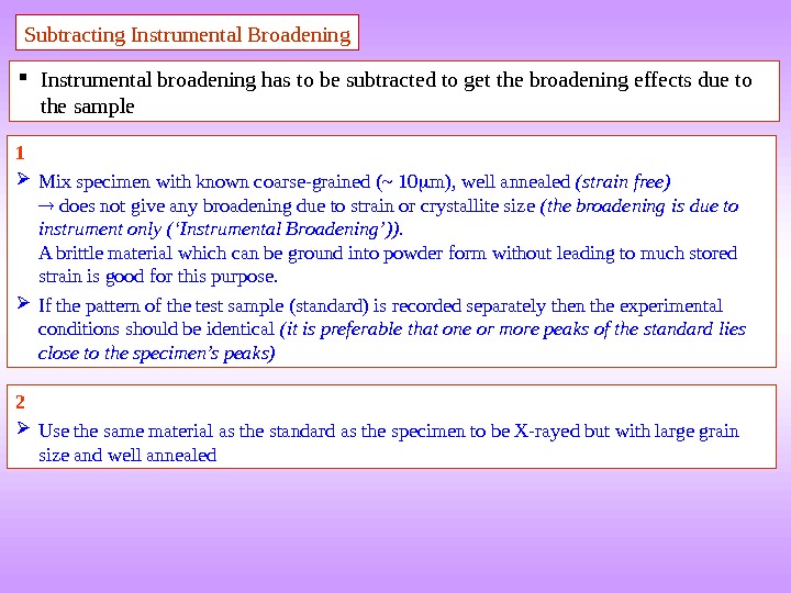
Subtracting Instrumental Broadening Instrumental broadening has to be subtracted to get the broadening effects due to the sample 1 Mix specimen with known coarse-grained (~ 10 m), well annealed (strain free) does not give any broadening due to strain or crystallite size (the broadening is due to instrument only (‘Instrumental Broadening’)). A brittle material which can be ground into powder form without leading to much stored strain is good for this purpose. If the pattern of the test sample (standard) is recorded separately then the experimental conditions should be identical (it is preferable that one or more peaks of the standard lies close to the specimen’s peaks) 2 Use the same material as the standard as the specimen to be X-rayed but with large grain size and well annealed
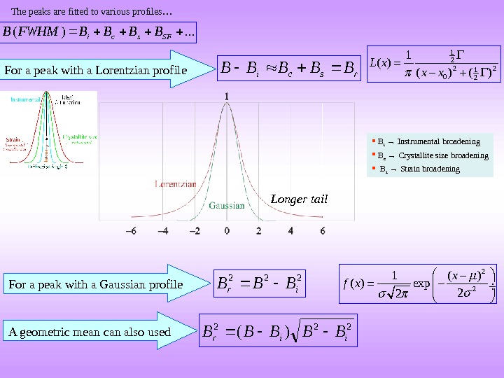
rsci. BBBBB. . . )(SFsci. BBBBFWHMBFor a peak with a Lorentzian profile 222 ir BBB For a peak with a Gaussian profile 222 )( iir BBBBB A geometric mean can also used Longer tail. The peaks are fitted to various profiles… 1 2 2 2 1 0 21 ( ) ( )L x x x 2 21 ( ) exp 2 2 x f x B i → Instrumental broadening B c → Crystallite size broadening B s → Strain broadening
Scherrer’s formula( ) c B k B L Cos → Wavelength L → Average crystallite size ( to surface of specimen) k → 0. 94 [k (0. 89, 1. 39)] ~ 1 (the accuracy of the method is only 10%? )For Gaussian line profiles and cubic crystals The Scherrer’s formula is used for the determination of grain size from broadened peaks. The formula is not expected to be valid for very small grain sizes (<10 nm)
Strain broadening ( ) s BB Tan → Strain in the material Smaller angle peaks should be used to separate B s and B c
Separating crystallite size broadening and strain broadening scr BBB )( Cos. L k B c )(Tan. B s )( )( Tan Cos. L k B r )()( Sin Lk Cos. B r Plot of [B r Cos ] vs [Sin ]Crystallite size broadening Strain broadening
Example of a calculation Sample: Annealed Al Radiation: Cu k ( = 1. 54 Å) Sample: Cold-worked Al Radiation: Cu k ( = 1. 54 Å)
Annealed Al Peak No. 2 ( ) hkl B i = FWHM ( ) B i = FWHM (rad) 1 38. 52 111 0. 103 1. 8 10 − 3 2 44. 76 200 0. 066 1. 2 10 − 3 3 65. 13 220 0. 089 1. 6 10 − 3 Cold-worked Al 2 ( ) Sin( ) hkl B ( ) B (rad) B r Cos (rad) 1 38. 51 0. 3298 111 0. 187 3. 3 10 − 3 2. 8 10 − 3 2. 6 10 − 3 2 44. 77 0. 3808 200 0. 206 3. 6 10 − 3 3. 4 10 − 3 3. 1 10 − 3 3 65. 15 0. 5384 220 0. 271 4. 7 10 − 3 4. 4 10 − 3 3. 7 10 − 3222 ir.
3 107. 1 Lk nm. LSize. Grain 90)(