978e3aeba6cd048047a3d08ed503c565.ppt
- Количество слайдов: 52


PRESENTATION ON Submitted By: Amit Gupta ECE’ 06 6220406501

EEAST is a complete R & D Organization dedicated to provide Electronics and Advanced Software Products and Solutions to its Clients. Achieving the needs of our customer and converting their ideas to real models is our motto. We are working in the field of Embedded Systems, Automation and Advanced System design for the last four years with the vision of becoming a center of Excellence to provide Solutions, Services and Training in various fields of technologies.

Embedded System • Embedded system means the processor is embedded into that application. • An embedded product uses a microprocessor or microcontroller to do one task only. • In an embedded system, there is only one application software that is typically burned into ROM. • Example:printer, keyboard, video game player

Embedded systems • Things with computers that are not computers themselves – Refrigerators, toys, industrial robots, . . . • 98% of all microprocessors go into embedded systems – Embedded systems are everywhere! – 50% much smaller than PC microprocessors • 8 -bit microprocessors

Embedded Computing Systems • Use a microprocessor or microcontroller to do one task only – Printer • PC used for any number of applications – Word processor, print-server, bank teller terminal, video game player, network server, internet terminal • PC contains or is connected to various embedded products – Keyboard, printer, modem, disk controller, sound card, CD-ROM driver, mouse • X 86 PC embedded applications

Embedded Products Using Microcontrollers • Home – Appliances, intercom, telephones, security systems, garage door openers, answering machines, fax machines, home computers, TVs, cable TV tuner, VCR, camcorder, remote controls, video games, cellular phones, musical instruments, sewing machines, lighting control, paging, camera, pinball machines, toys, exercise equipment

Embedded Products Using Microcontrollers • Office – Telephones, computers, security systems, fax machines, microwave, copier, laser printer, color printer, paging

Embedded Products Using Microcontrollers • Auto – Trip computer, engine control, air bag, ABS, instrumentation, security system, transmission control, entertainment, climate control, cellular phone, keyless entry

Why do we need to learn Microprocessors/controllers? • The microprocessor is the core of computer systems. • Nowadays many communication, digital entertainment, portable devices, are controlled by them. • A designer should know what types of components he needs, ways to reduce production costs and product reliable.

Introduction General-purpose microprocessor • CPU for Computers • No RAM, ROM, I/O on CPU chip itself • Example:Intel’s x 86, Motorola’s 680 x 0 CPU General. Purpose Microprocessor Many chips on mother’s board Data Bus RAM ROM I/O Port Address Bus General-Purpose Microprocessor System Timer Serial COM Port

Microprocessor vs. Microcontroller Microprocessor • CPU is stand-alone, RAM, ROM, I/O, timer are separate • designer can decide on the amount of ROM, RAM and I/O ports. • expansive • versatility • general-purpose Microcontroller • CPU, RAM, ROM, I/O and timer are all on a single chip • fix amount of on-chip ROM, RAM, I/O ports • for applications in which cost, power and space are critical • single-purpose

Microprocessor vs. Microcontroller

Choosing A Microcontroller • Computing needs – Speed, packaging, power consumption, RAM, ROM, I/O pins, timers, upgrade to high performance or low-power versions, cost • Software development tools – Assembler, debugger, C compiler, emulator, technical support • Availability & source

Microcontroller : • A smaller computer • On-chip RAM, ROM, I/O ports. . . • Example:Motorola’s 6811, Intel’s 8051, Zilog’s Z 8 and PIC 16 X CPU I/O Port RAM ROM Serial Timer COM Port A single chip Microcontroller

Companies Producing 8051/8952 • Some Companies Producing a Member of the 8051/8952 Family Company Web Site Intel www. intel. com/design/mcs 51 Atmel www. atmel. com Philips/Signetics www. semiconductors. philips. com Siemens www. sci. siemens. com Dallas Semiconductor www. dalsemi. com

Advantages of using MCU • • • Small – Single chip is smaller than a PC Cheap Low power consumption Low heat High efficiency – have only required units

Three criteria in Choosing a Microcontroller 1. meeting the computing needs of the task efficiently and cost effectively • speed, the amount of ROM and RAM, the number of I/O ports and timers, size, packaging, power consumption • easy to upgrade • cost per unit 2. availability of software development tools • assemblers, debuggers, C compilers, emulator, simulator, technical support 3. wide availability and reliable sources of the microcontrollers.

Contents: Introduction Block Diagram and Pin Description of the AT 89 C 52. Registers Memory mapping in AT 89 C 52 Flag bits and the PSW register Stack in the AT 89 C 52.

8051 Family • Comparison of 8051 Family Members Feature 8051 8052 8031 ROM (on chip program space in bytes) 4 K 8 k 0 k RAM (bytes) 128 256 128 Timers 2 3 2 I/O pins 32 32 32 Serial port 1 1 1 Interrupt sources 6 8 6

Inside 8051 Microcontroller • Introduced by Intel in 1981

Pin Description of the 8051 P 1. 0 P 1. 1 P 1. 2 P 1. 3 P 1. 4 P 1. 5 P 1. 6 P 1. 7 RST (RXD)P 3. 0 (TXD)P 3. 1 (INT 0)P 3. 2 (INT 1)P 3. 3 (T 0)P 3. 4 (T 1)P 3. 5 (WR)P 3. 6 (RD)P 3. 7 XTAL 2 XTAL 1 GND 1 2 3 4 5 6 7 8 9 10 11 12 13 14 15 16 17 18 19 20 8051 40 39 38 37 36 35 34 33 32 31 30 29 28 27 26 25 24 23 22 21 Vcc P 0. 0(AD 0 ) 0. 1(AD 1) P P 0. 2(AD 2 ) 0. 3(AD 3) P P 0. 4(AD 4) P 0. 5(AD 5) P 0. 6(AD 6) P 0. 7(AD 7) EA/VPP ALE/PROG PSEN P 2. 7(A 15) P 2. 6(A 14) P 2. 5(A 13) P 2. 4(A 12) P 2. 3(A 11) P 2. 2(A 10) P 2. 1(A 9) P 2. 0(A 8)
 • Vcc(pin 40): – Vcc provides supply voltage to the chip.")
Pins of 8051(1/4) • Vcc(pin 40): – Vcc provides supply voltage to the chip. – The voltage source is +5 V. • GND(pin 20):ground • XTAL 1 and XTAL 2(pins 19, 18): – These 2 pins provide external clock. – Way 1:using a quartz crystal oscillator – Way 2:using a TTL oscillator – Example 4 -1 shows the relationship between XTAL and the machine cycle.
 • RST(pin 9):reset – It is an input pin and is")
Pins of 8051(2/4) • RST(pin 9):reset – It is an input pin and is active high(normally low). • The high pulse must be high at least 2 machine cycles. – It is a power-on reset. • Upon applying a high pulse to RST, the microcontroller will reset and all values in registers will be lost. • Reset values of some 8051 registers – Way 1:Power-on reset circuit – Way 2:Power-on reset with debounce

Pins of I/O Port • The 8051 has four I/O ports – Port 0 (pins 32 -39):P 0(P 0. 0~P 0. 7) – Port 1(pins 1 -8) :P 1(P 1. 0~P 1. 7) – Port 2(pins 21 -28):P 2(P 2. 0~P 2. 7) – Port 3(pins 10 -17):P 3(P 3. 0~P 3. 7) – Each port has 8 pins. • Named P 0. X (X=0, 1, . . . , 7), P 1. X, P 2. X, P 3. X • Ex:P 0. 0 is the bit 0(LSB)of P 0 • Ex:P 0. 7 is the bit 7(MSB)of P 0 • These 8 bits form a byte. • Each port can be used as input or output (bi-direction).
 • /EA(pin 31):external access – There is no on-chip ROM in")
Pins of 8051(3/4) • /EA(pin 31):external access – There is no on-chip ROM in 8031 and 8032. – The /EA pin is connected to GND to indicate the code is stored externally. – /PSEN & ALE are used for external ROM. – For 8051, /EA pin is connected to Vcc. – “/” means active low. • /PSEN(pin 29):program store enable – This is an output pin and is connected to the OE pin of the ROM.
 • ALE(pin 30):address latch enable – It is an output pin")
Pins of 8051(4/4) • ALE(pin 30):address latch enable – It is an output pin and is active high. – 8051 port 0 provides both address and data. – The ALE pin is used for de-multiplexing the address and data by connecting to the G pin of the 74 LS 373 latch. • I/O port pins – The four ports P 0, P 1, P 2, and P 3. – Each port uses 8 pins. – All I/O pins are bi-directional.

Dual Role of Port 0 • When connecting an 8051/8031 to an external memory, the 8051 uses ports to send addresses and read instructions. – 8031 is capable of accessing 64 K bytes of external memory. – 16 -bit address:P 0 provides both address A 0 -A 7, P 2 provides address A 8 -A 15. – Also, P 0 provides data lines D 0 -D 7. • When P 0 is used for address/data multiplexing, it is connected to the 74 LS 373 to latch the address. – There is no need for external pull-up resistors

Port 0 with Pull-Up Resistors Vcc Port 0 DS 5000 8751 8951 P 0. 0 P 0. 1 P 0. 2 P 0. 3 P 0. 4 P 0. 5 P 0. 6 P 0. 7 10 K

Registers A B R 0 R 1 R 2 PC PC R 3 R 4 R 5 R 6 R 7 Some 8 -bitt Registers of the 8051 Some 8051 16 -bit Register

8051 Flag bits and the PSW register • PSW Register CY AC F 0 RS 1 RS 0 OV -- P CYPSW. 7 Carry flag ACPSW. 6 Auxiliary carry flag --PSW. 5 Available to the user for general purpose RS 1 PSW. 4 Register Bank selector bit 1 RS 0 PSW. 3 Register Bank selector bit 0 OVPSW. 2 Overflow flag --PSW. 1 User define bit PPSW. 0 Parity flag Set/Reset odd/even parity RS 1 RS 0 Register Bank Address 0 00 H-07 H 0 1 1 08 H-0 FH 1 0 2 10 H-17 H 1 1 3 18 H-1 FH

Stack in the 8051 • The register used to access the stack is called SP (stack pointer) register. 7 FH Scratch pad RAM 30 H • The stack pointer in the 8051 is only 8 bits wide, which means that it can take value 00 to FFH. When 8051 powered up, the SP register contains value 07. 2 FH Bit-Addressable RAM 20 H 1 FH 18 H 17 H 10 H 0 FH 08 H 07 H 00 H Register Bank 3 Register Bank 2 (Stack) Register Bank 1 Register Bank 0

Now we can program. . . ● But how do we get the programs onto the devices?

WITH THE USE OF KEIL SOFTWARE • Write a program in embedded C language. • Execute it. • View the output of program on peripheral devices as provided in Keil software. • Now burn the program on AT 89 C 52 using burner. • Now apply the chip with hardware.

Interfacing • hardware or software used to interface two computers or programs or devices

Interfacing used • • • LED Seven Segment Display LCD Display Stepper Motor Switch Buzzer

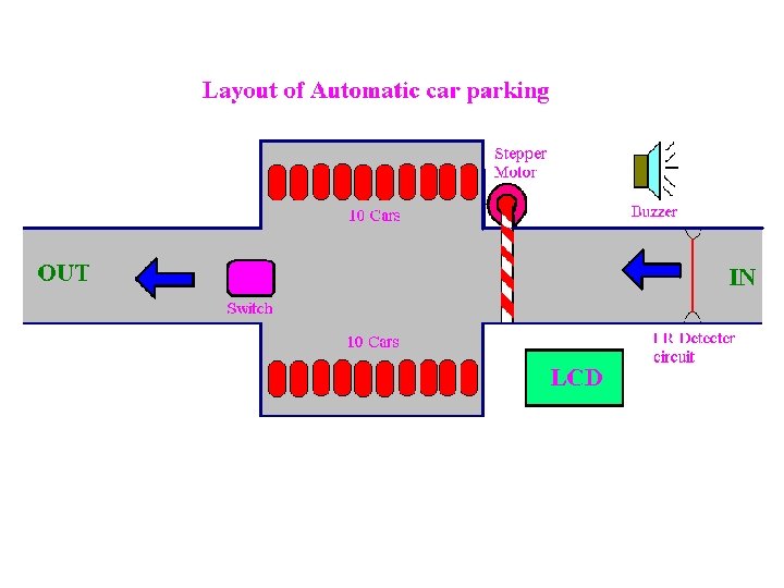
AUTOMATIC CAR PARKING • Block Diagram • Layout • Circuit Diagram

BLOCK DIAGRAM

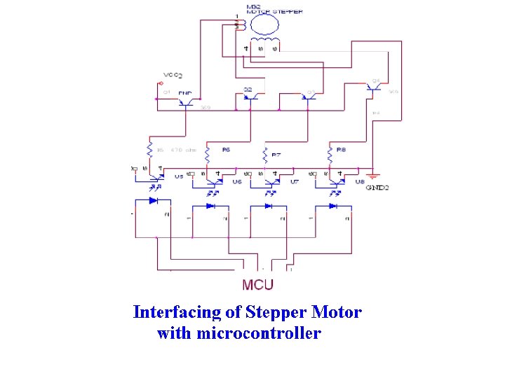
STEPPER MOTOR

STEPPER MOTOR • This animation demonstrates the principle for a stepper motor using full step commutation. The rotor of a permanent magnet stepper motor consists of permanent magnets and the stator has two pairs of windings. Just as the rotor aligns with one of the stator poles, the second phase is energized. The two phases alternate on and off and also reverse polarity. There are four steps. One phase lags the other phase by one step. This is equivalent to one forth of an electrical cycle or 90°.

STEPPER MOTOR • This stepper motor is very simplified. The rotor of a real stepper motor usually has many poles. The animation has only ten poles, however a real stepper motor might have a hundred. These are formed using a single magnet mounted inline with the rotor axis and two pole pieces with many teeth. The teeth are staggered to produce many poles. The stator poles of a real stepper motor also has many teeth. The teeth are arranged so that the two phases are still 90° out of phase. This stepper motor uses permanent magnets. Some stepper motors do not have magnets and instead use the basic principles of a switched reluctance motor. The stator is similar but the rotor is composed of a iron laminates.

STEPPER MOTOR • Note how the phases are driven so that the rotor takes half steps

STEPPER MOTOR • Animation shows how coils are energized for full steps

STEPPER MOTOR • Full step sequence showing how binary numbers can control the motor • Half step sequence of binary control numbers

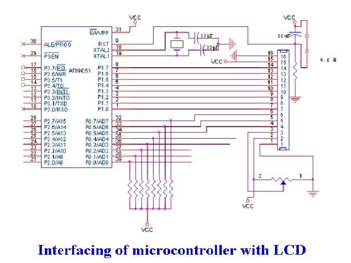
LCD Display

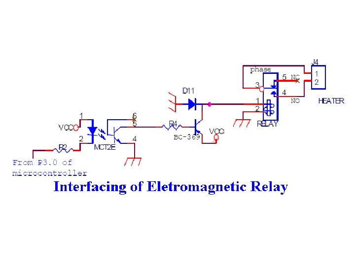
Optocoupler Devices IC’s used in Automation , to provide isolation Why isolation is required? Because microcontroller works on 5 V and other devices(Stepper Motor , Fan) works on greater than 5 V. Any spike of greater of 5 V can burn microcontroller.

Pin diagram of 4 N 35

Electromagnetic Relay
978e3aeba6cd048047a3d08ed503c565.ppt