Potentiometer sensor 2. 3. 1 Potentiometer sensor A


sensors_and_transducers_lecture_19_03_13.ppt
- Количество слайдов: 18
 Potentiometer sensor
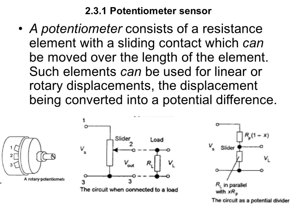
 2.3.1 Potentiometer sensor A potentiometer consists of a resistance element with a sliding contact which can be moved over the length of the element. Such elements can be used for linear or rotary displacements, the displacement being converted into a potential difference.
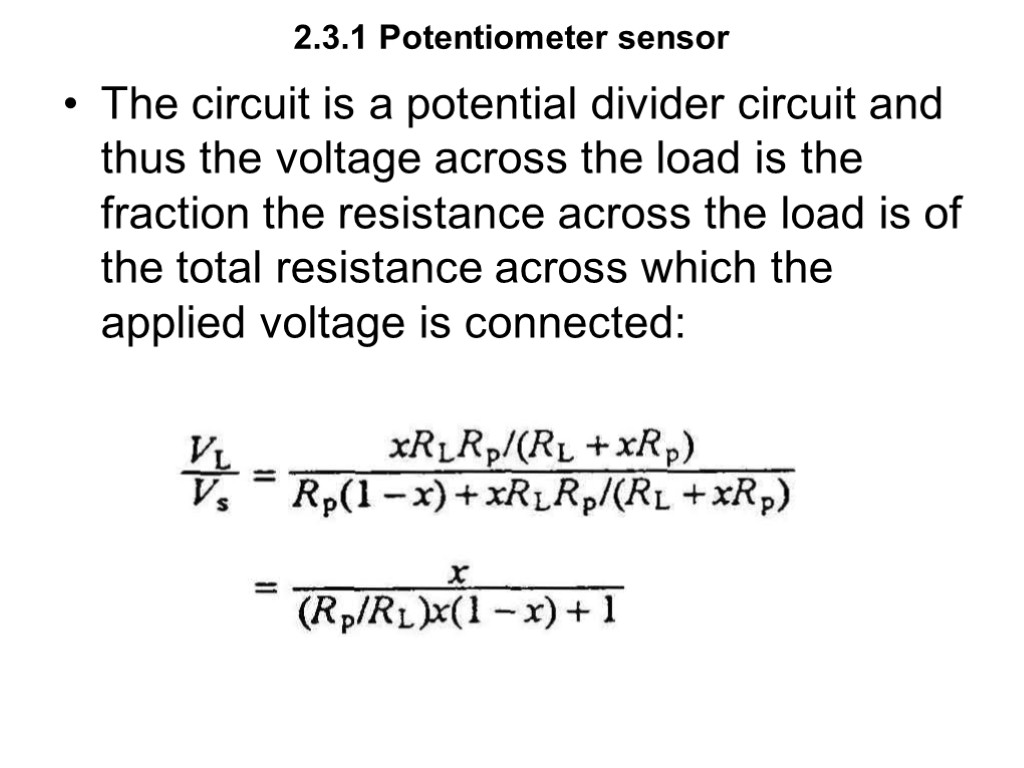
 2.3.1 Potentiometer sensor The circuit is a potential divider circuit and thus the voltage across the load is the fraction the resistance across the load is of the total resistance across which the applied voltage is connected:
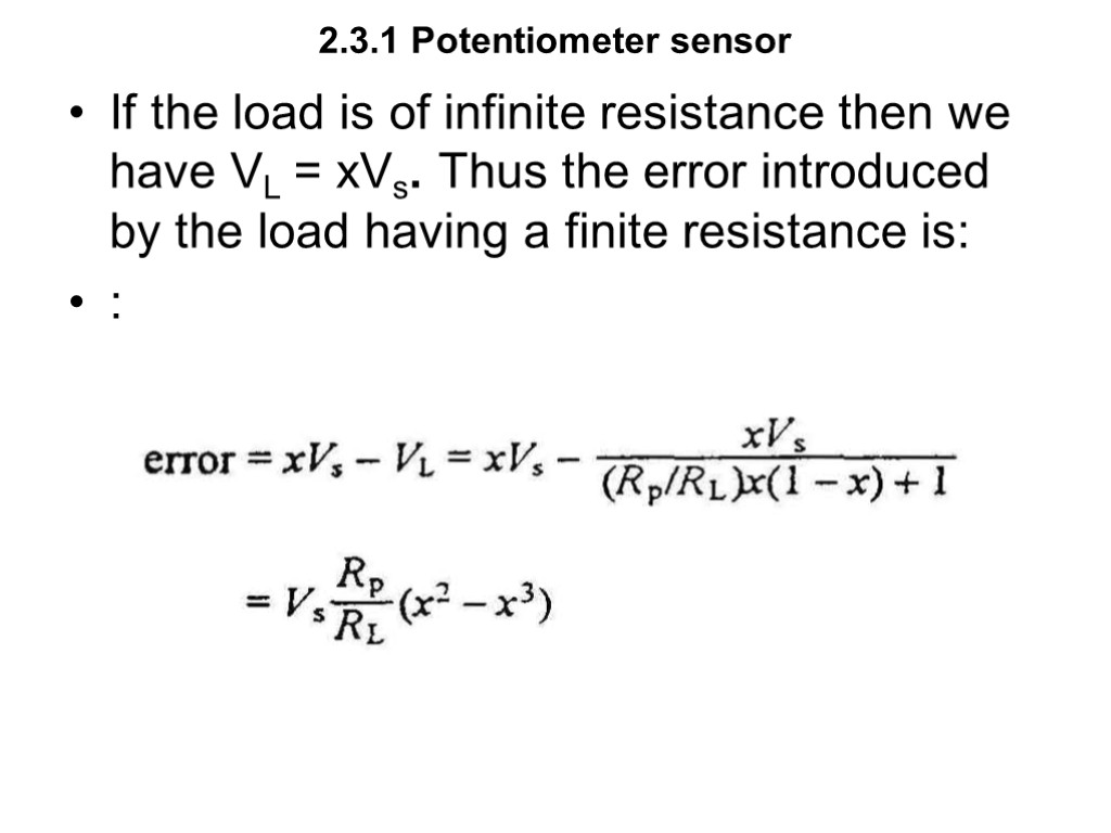
 2.3.1 Potentiometer sensor If the load is of infinite resistance then we have VL = xVs. Thus the error introduced by the load having a finite resistance is: :
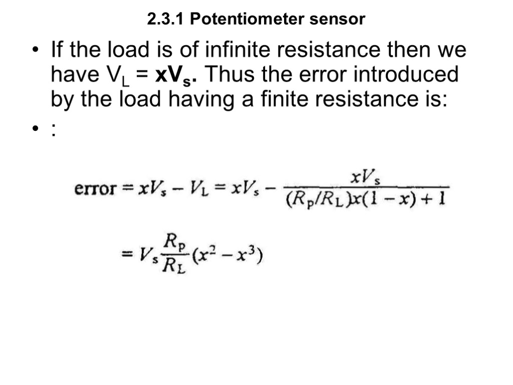
 2.3.1 Potentiometer sensor If the load is of infinite resistance then we have VL = xVs. Thus the error introduced by the load having a finite resistance is: :
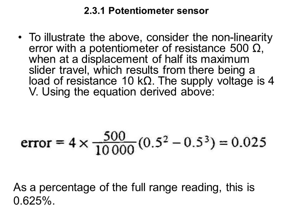
 2.3.1 Potentiometer sensor To illustrate the above, consider the non-linearity error with a potentiometer of resistance 500 Ω, when at a displacement of half its maximum slider travel, which results from there being a load of resistance 10 kΩ. The supply voltage is 4 V. Using the equation derived above: As a percentage of the full range reading, this is 0.625%.
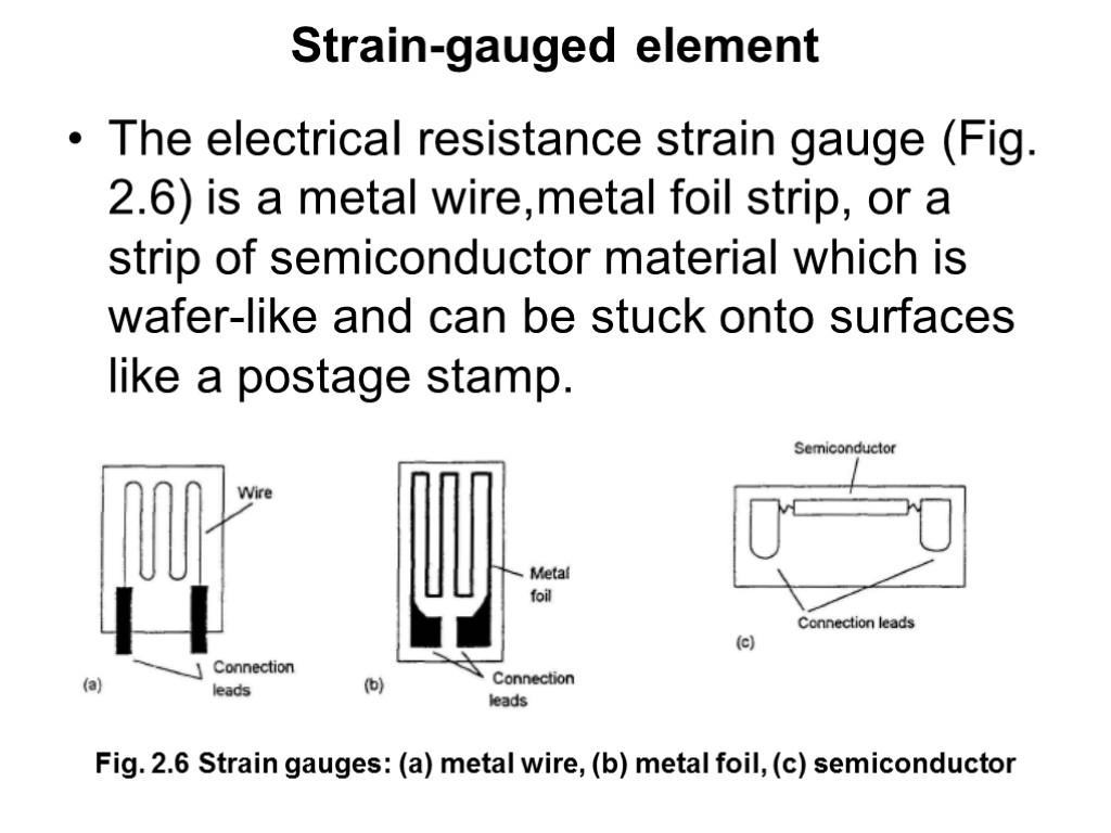
 Strain-gauged element The electricaI resistance strain gauge (Fig. 2.6) is a metal wire,metal foil strip, or a strip of semiconductor material which is wafer-like and can be stuck onto surfaces like a postage stamp. Fig. 2.6 Strain gauges: (a) metal wire, (b) metal foil, (c) semiconductor
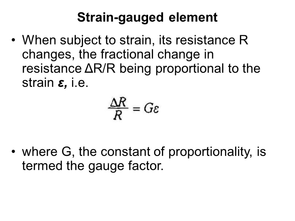
 Strain-gauged element When subject to strain, its resistance R changes, the fractional change in resistance ΔR/R being proportional to the strain ε, i.e. where G, the constant of proportionality, is termed the gauge factor.
 Strain-gauged element The gauge factor of metal wire or foil strain gauges with the metals generally used is about 2.0. Silicon p- and n-type semiconductor strain gauges have gauge factors of about +100 or more for p-type silicon and -100 or more for n-type silicon. A problem with all strain gauges is that their resistance not only changes with strain but also with temperature. Semiconductor strain gauges have a much greater sensitivity to teimperature than metal strain gauges.
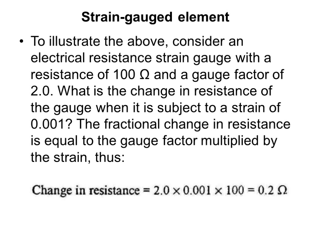
 Strain-gauged element To illustrate the above, consider an electrical resistance strain gauge with a resistance of 100 Ω and a gauge factor of 2.0. What is the change in resistance of the gauge when it is subject to a strain of 0.001? The fractional change in resistance is equal to the gauge factor multiplied by the strain, thus:
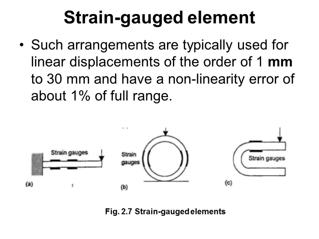
 Such arrangements are typically used for linear displacements of the order of 1 mm to 30 mm and have a non-linearity error of about 1% of full range. Strain-gauged element Fig. 2.7 Strain-gauged elements
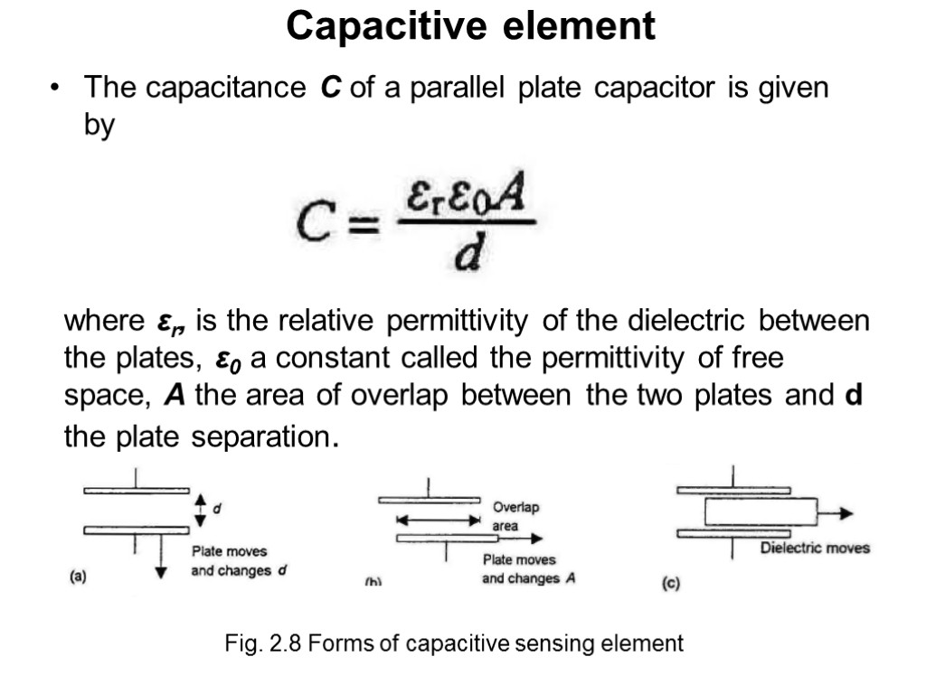
 Capacitive element The capacitance C of a parallel plate capacitor is given by where εr, is the relative permittivity of the dielectric between the plates, ε0 a constant called the permittivity of free space, A the area of overlap between the two plates and d the plate separation. Fig. 2.8 Forms of capacitive sensing element
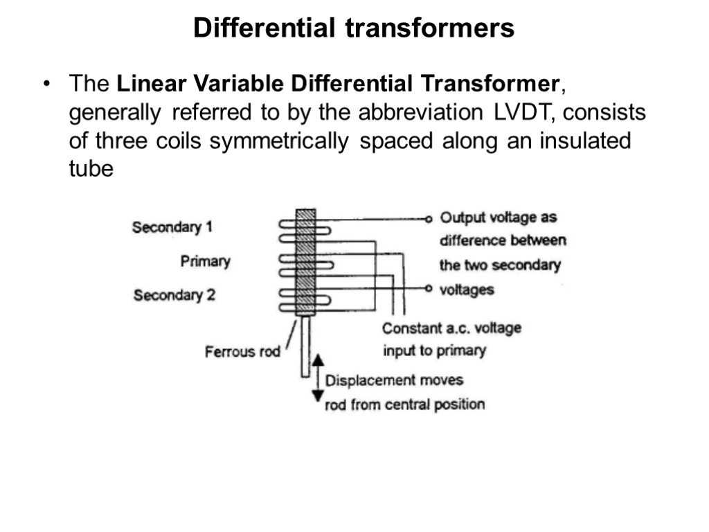
 Differential transformers The Linear Variable Differential Transformer, generally referred to by the abbreviation LVDT, consists of three coils symmetrically spaced along an insulated tube
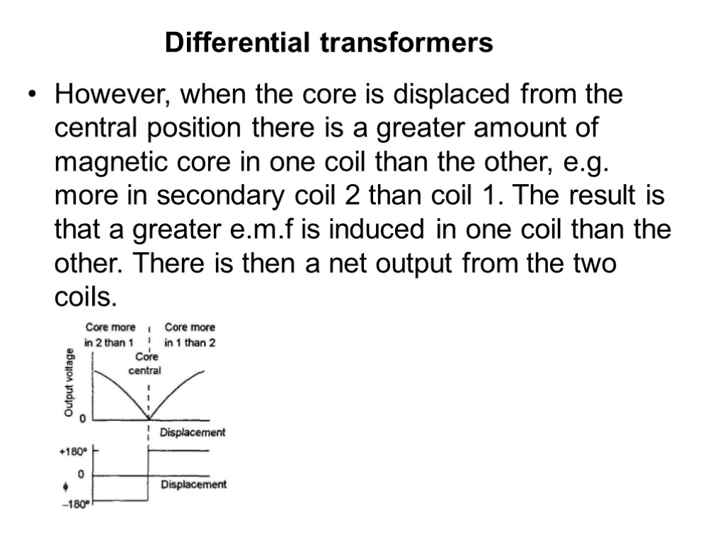
 However, when the core is displaced from the central position there is a greater amount of magnetic core in one coil than the other, e.g. more in secondary coil 2 than coil 1. The result is that a greater e.m.f is induced in one coil than the other. There is then a net output from the two coiIs. Differential transformers
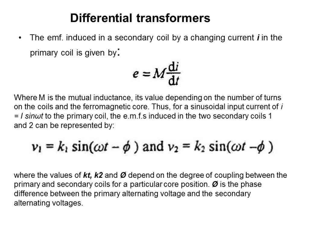
 The emf. induced in a secondary coil by a changing current i in the primary coil is given by: Where M is the mutual inductance, its value depending on the number of turns on the coils and the ferromagnetic core. Thus, for a sinusoidal input current of i = I sinωt to the primary coil, the e.m.f.s induced in the two secondary coils 1 and 2 can be represented by: where the values of kt, k2 and Ø depend on the degree of coupling between the primary and secondary coils for a particular core position. Ø is the phase difference between the primary alternating voltage and the secondary alternating voltages. Differential transformers
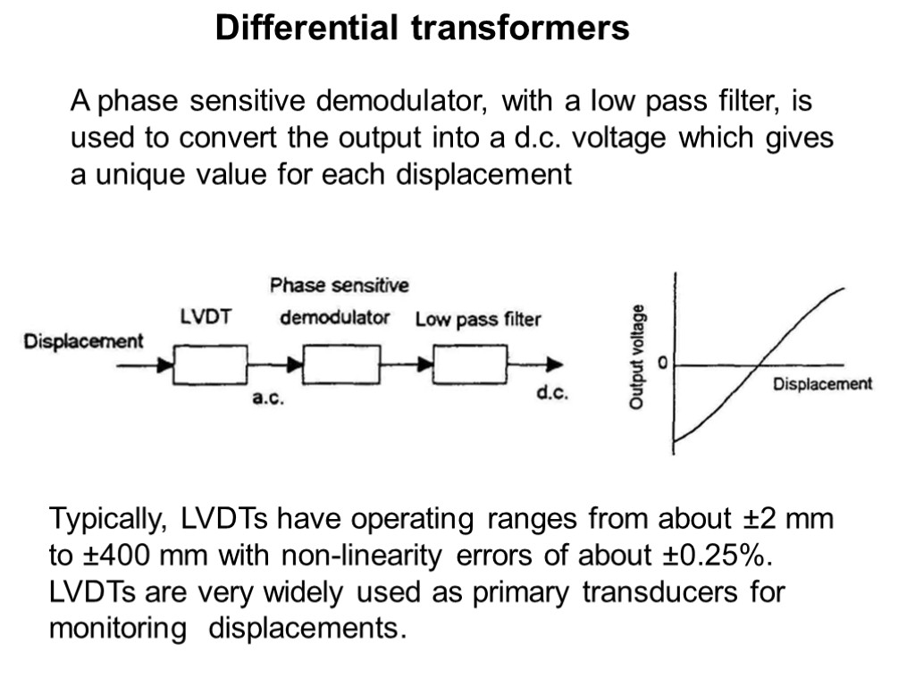
 Differential transformers A phase sensitive demodulator, with a Iow pass filter, is used to convert the output into a d.c. voltage which gives a unique value for each displacement Typically, LVDTs have operating ranges from about ±2 mm to ±400 mm with non-linearity errors of about ±0.25%. LVDTs are very widely used as primary transducers for monitoring displacements.
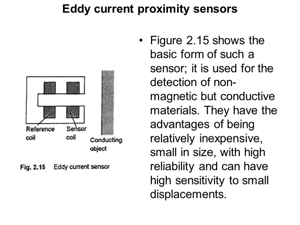
 Eddy current proximity sensors If a coil is supplied with an alternating current, an alternating magnetic field is produced. If there is a metal object in close proximity to this alternating magnetic field, then eddy currents are induced in it. The eddy currents tliemselves produce a magnetic field. This distorts the magnetic field responsible for their production. As a result, the impedance of the coil changes and so the amplitude of the alternating current. At some preset level, this change can be used to trigger a switch.
 Figure 2.15 shows the basic form of such a sensor; it is used for the detection of non-magnetic but conductive materials. They have the advantages of being relatively inexpensive, small in size, with high reliability and can have high sensitivity to small displacements. Eddy current proximity sensors

