
ONE-TRAX ®® Overview ONE-TRAX Overview


one-trax_v1.3_presentation_-_complete.ppt
- Размер: 8.3 Mегабайта
- Количество слайдов: 232
Описание презентации ONE-TRAX ®® Overview ONE-TRAX Overview по слайдам
ONE-TRAX ®® Overview
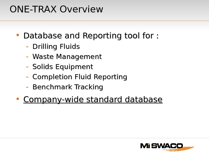
ONE-TRAX Overview • Database and Reporting tool for : — Drilling Fluids — Waste Management — Solids Equipment — Completion Fluid Reporting — Benchmark Tracking • Company-wide standard database
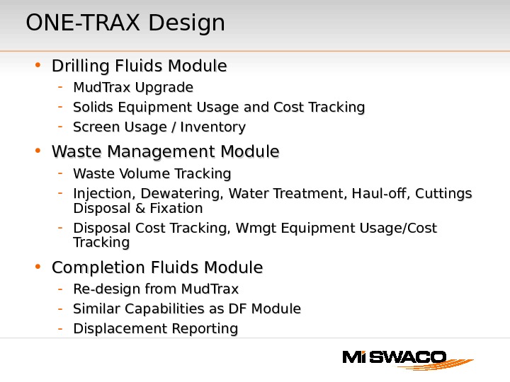
ONE-TRAX Design • Drilling Fluids Module — Mud. Trax Upgrade — Solids Equipment Usage and Cost Tracking — Screen Usage / Inventory • Waste Management Module — Waste Volume Tracking — Injection, Dewatering, Water Treatment, Haul-off, Cuttings Disposal & Fixation — Disposal Cost Tracking, Wmgt Equipment Usage/Cost Tracking • Completion Fluids Module — Re-design from Mud. Trax — Similar Capabilities as DF Module — Displacement Reporting
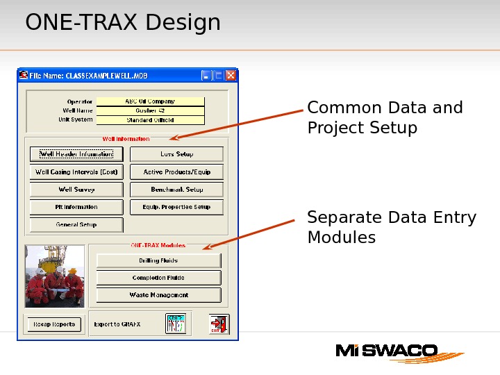
Common Data and Project Setup Separate Data Entry Modules. ONE-TRAX Design
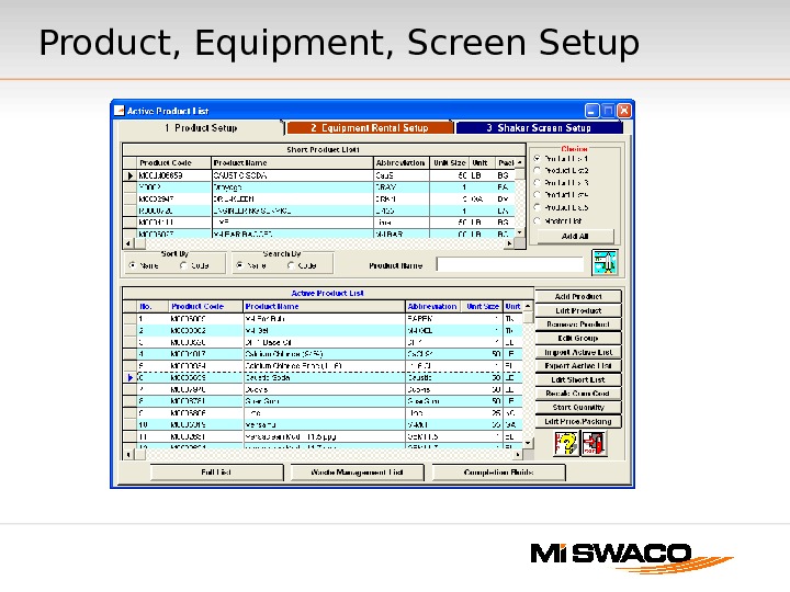
Product, Equipment, Screen Setup
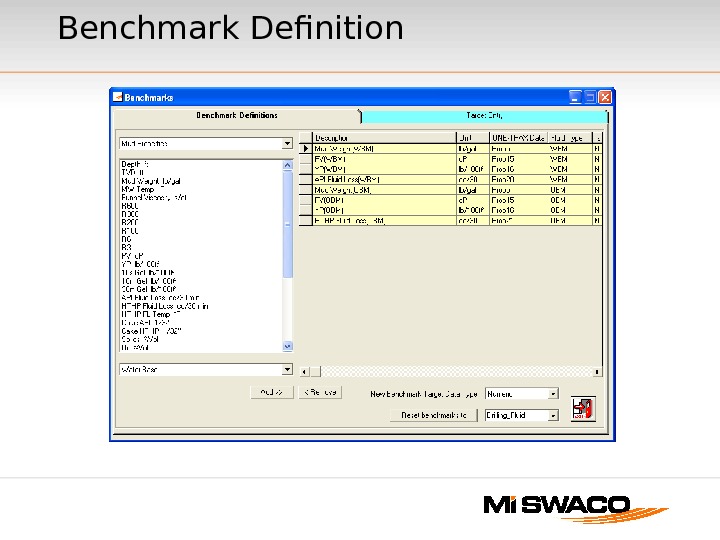
Benchmark Definition
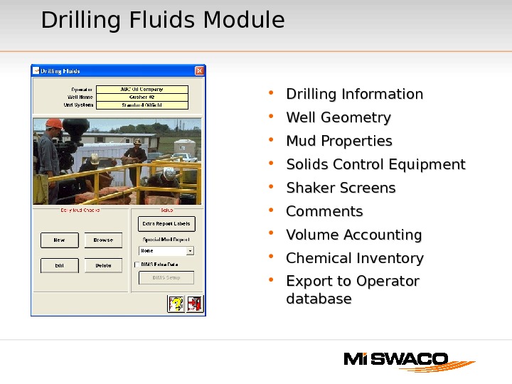
Drilling Fluids Module • Drilling Information • Well Geometry • Mud Properties • Solids Control Equipment • Shaker Screens • Comments • Volume Accounting • Chemical Inventory • Export to Operator database
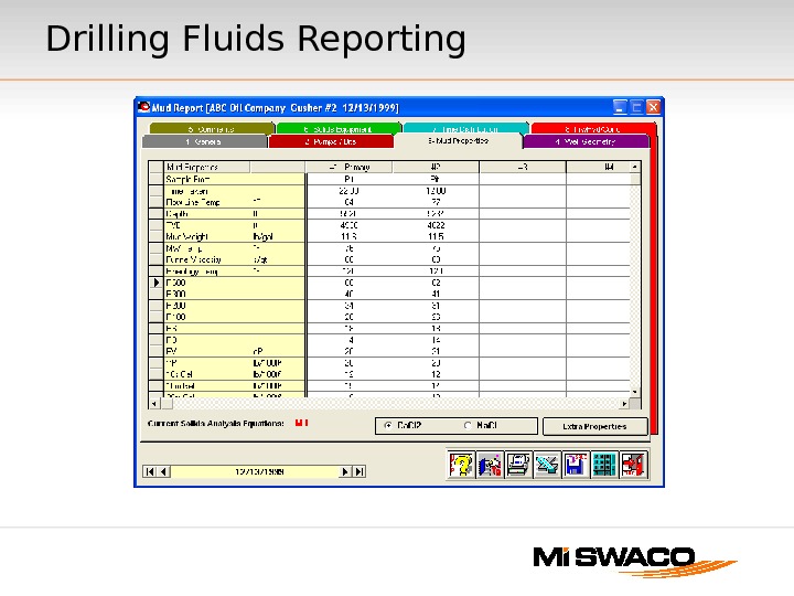
Drilling Fluids Reporting
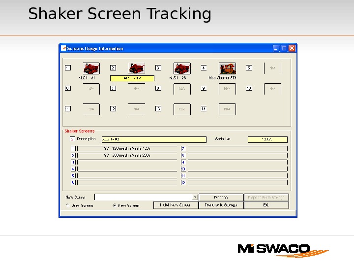
Shaker Screen Tracking
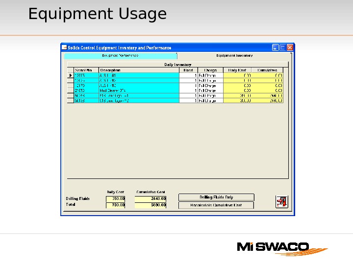
Equipment Usage
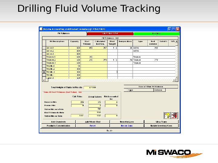
Drilling Fluid Volume Tracking
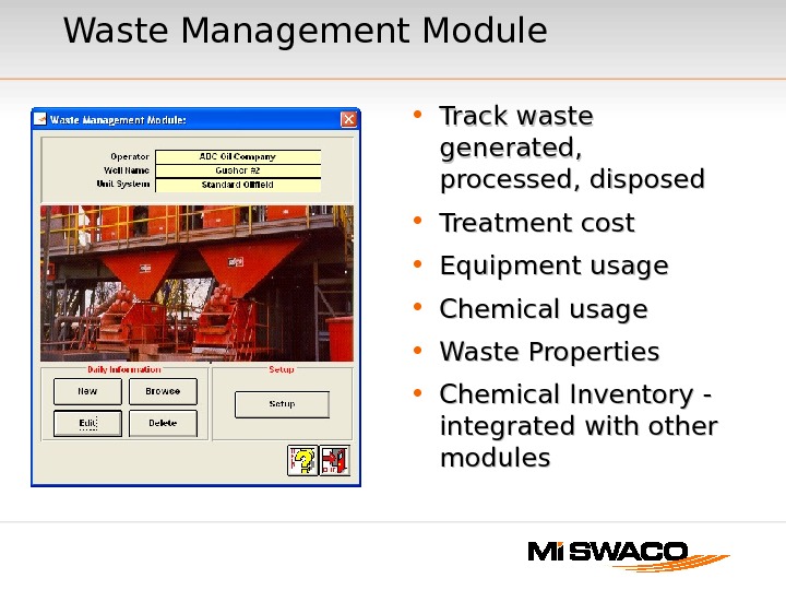
Waste Management Module • Track waste generated, processed, disposed • Treatment cost • Equipment usage • Chemical usage • Waste Properties • Chemical Inventory — integrated with other modules
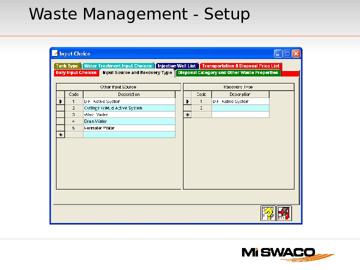
Waste Management — Setup
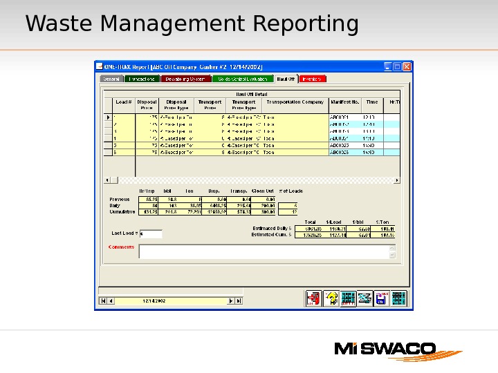
Waste Management Reporting
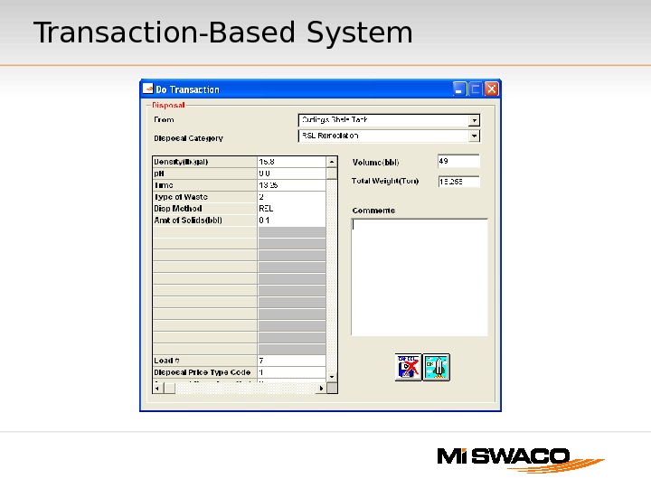
Transaction-Based System
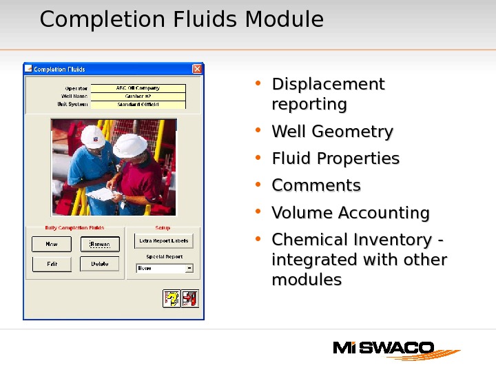
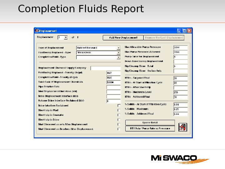
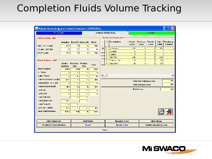
Completion Fluids Module • Displacement reporting • Well Geometry • Fluid Properties • Comments • Volume Accounting • Chemical Inventory — integrated with other modules
Completion Fluids Report
Completion Fluids Volume Tracking
Custom Reporting • Excel Report Templates — Linked to ONE-TRAX database — Daily Reports — Recap Reports — IFE report design will need to be project specific — budget time for report design and linking
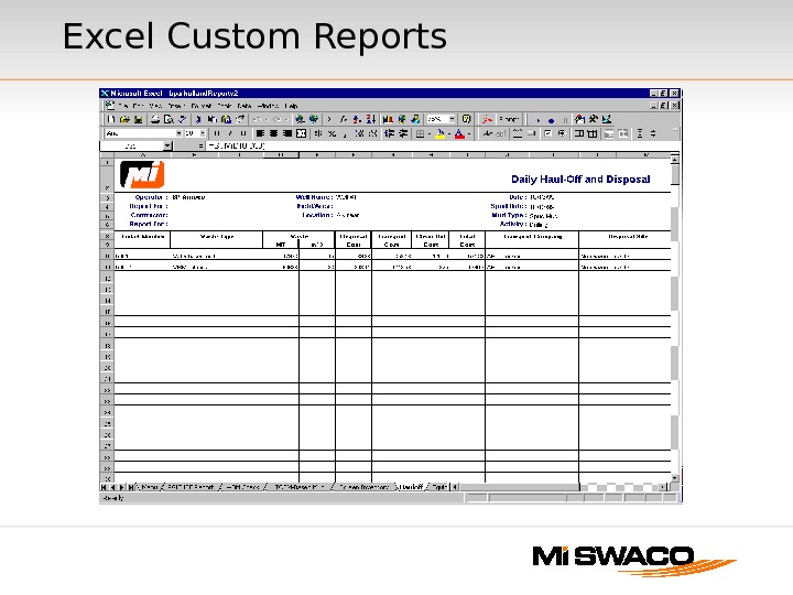
Excel Custom Reports
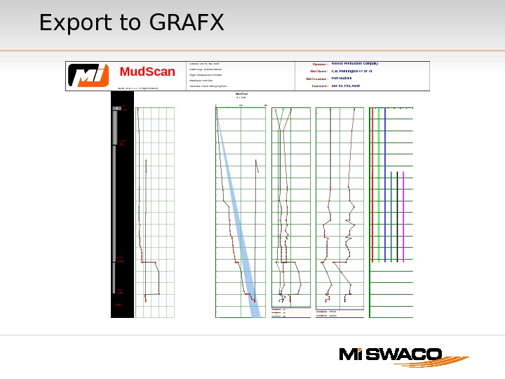
Export to GRAFX Operator : Well Name : Well Location : Comment : Amoco Production Company C. B. Pennington #7 ST #1 Port Hudson Sec 43, T 5 S, R 2 WLocation: Sec 43, T 5 S, R 2 W District Engr: Charles Freeman Engrs: Glasspool and Primeaux Warehouse: Port Allen Contractor: Parker Drilling Rig #182 Mud. Scan © 1996, 99 M-I L. L. C. — All Rights Reserved Depth ft 1000 2000 3000 4000 5000 6000 7000 8000 9000 10000 11000 12000 13000 14000 15000 16000 17000 18000 Formation Tops U. Tertiary Het Lime Vicksburg Sparta Wilcox test Tuscaloosa B. Tuscaloosa Casing Program 16995 16664 7 -5/8″ L 15964 15906 9 -5/8″ 13243 13185 13 -3/8″ 3225 24″ 267 8 10 12 14 16 18 Mud Weight lb/gal Mud Type FW Spud 13. 0 -ppg VERSADRIL 10. 5 -ppg VERSADRIL 0 100 200 Mud Cost $ x 1000 0 20 40 PV, YP, R 3 cps, lb/100 ft 2 PV YP R 3 0 20 40 Gel 10 s, Gel 10 m lb/100 ft 2 Gel 10 s Gel 10 m Solids Control L Shaker Desander Desilter Cleaner Lo Cent Hi Cent Unitized Depth ft
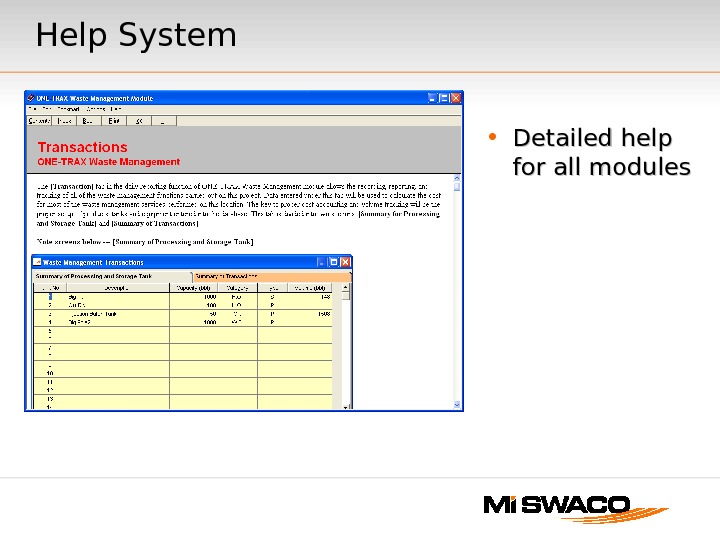
Help System • Detailed help for all modules
This page intentionally left blank.
Break Time
ONE-TRAX ®® v 1. 3 Well Startup Illustrated instructions for starting a new ONE-TRAX file
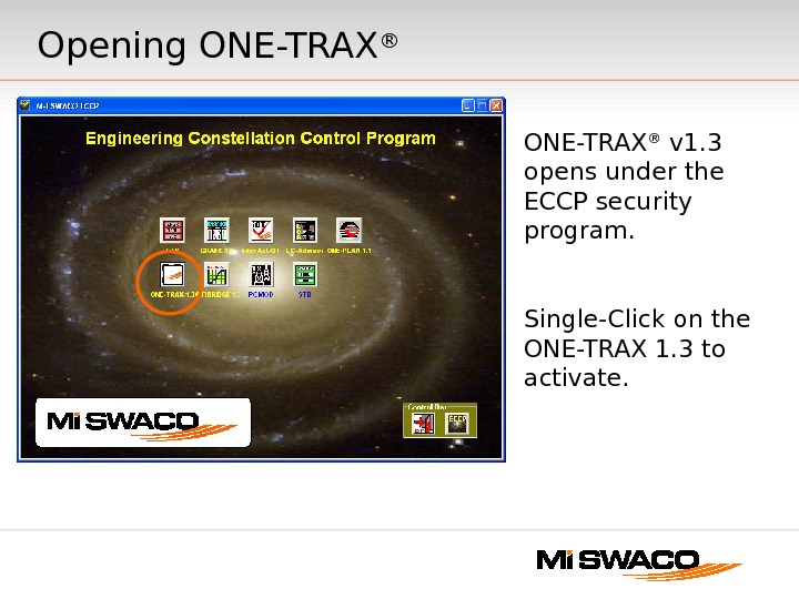
Opening ONE-TRAX ® v 1. 3 opens under the ECCP security program. Single-Click on the ONE-TRAX 1. 3 to activate.
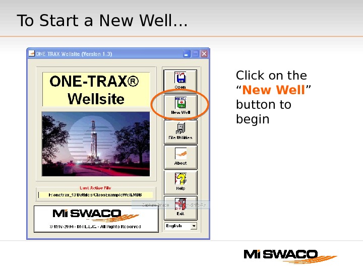
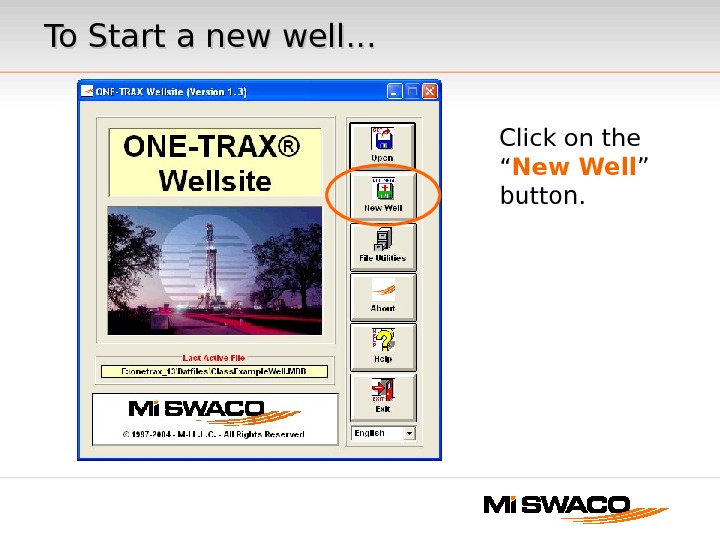
To Start a New Well. . . Click on the “ New Well ” button to begin
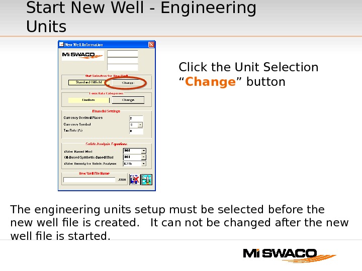
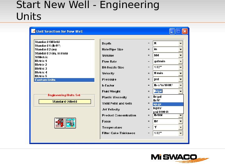
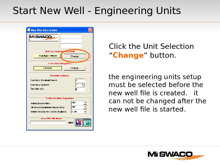
Start New Well — Engineering Units Click the Unit Selection “ Change ” button The engineering units setup must be selected before the new well file is created. It can not be changed after the new well file is started.
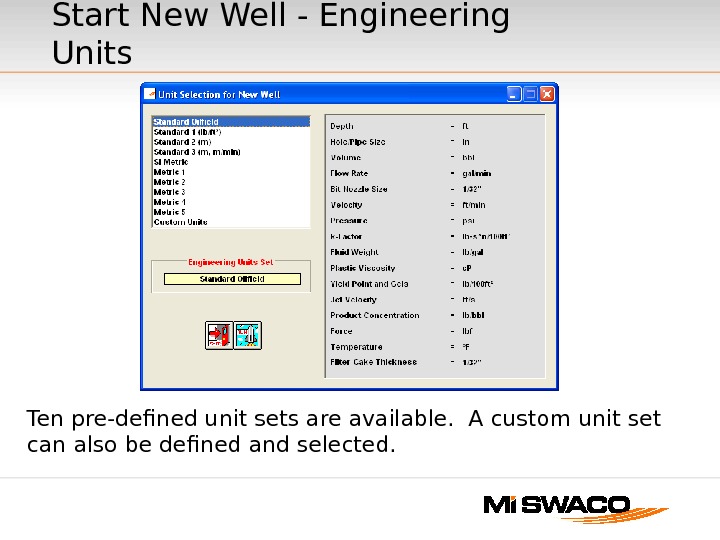
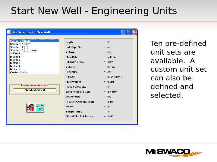
Ten pre-defined unit sets are available. A custom unit set can also be defined and selected. Start New Well — Engineering Units
Start New Well — Engineering Units
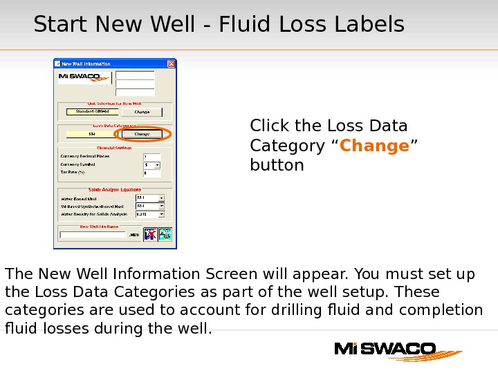
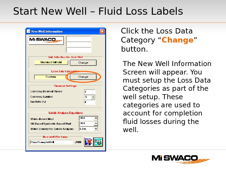
Start New Well — Fluid Loss Labels Click the Loss Data Category “ Change ” button The New Well Information Screen will appear. You must set up the Loss Data Categories as part of the well setup. These categories are used to account for drilling fluid and completion fluid losses during the well.
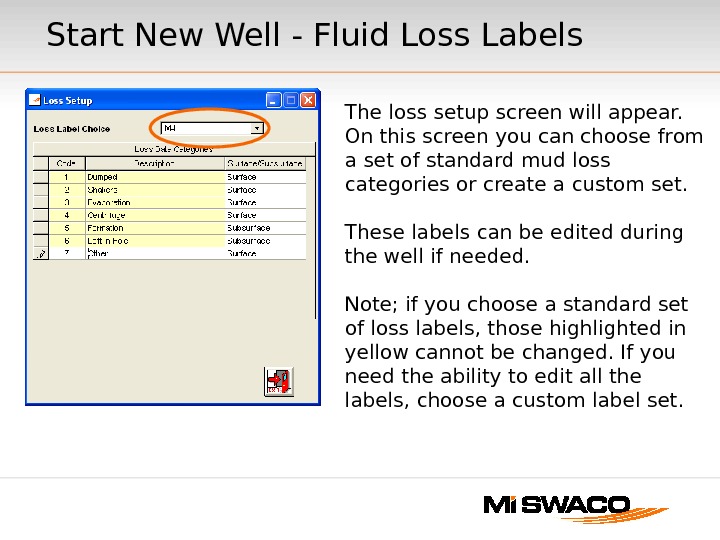
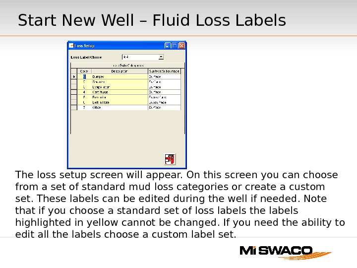
Start New Well — Fluid Loss Labels The loss setup screen will appear. On this screen you can choose from a set of standard mud loss categories or create a custom set. These labels can be edited during the well if needed. Note; if you choose a standard set of loss labels, those highlighted in yellow cannot be changed. If you need the ability to edit all the labels, choose a custom label set.
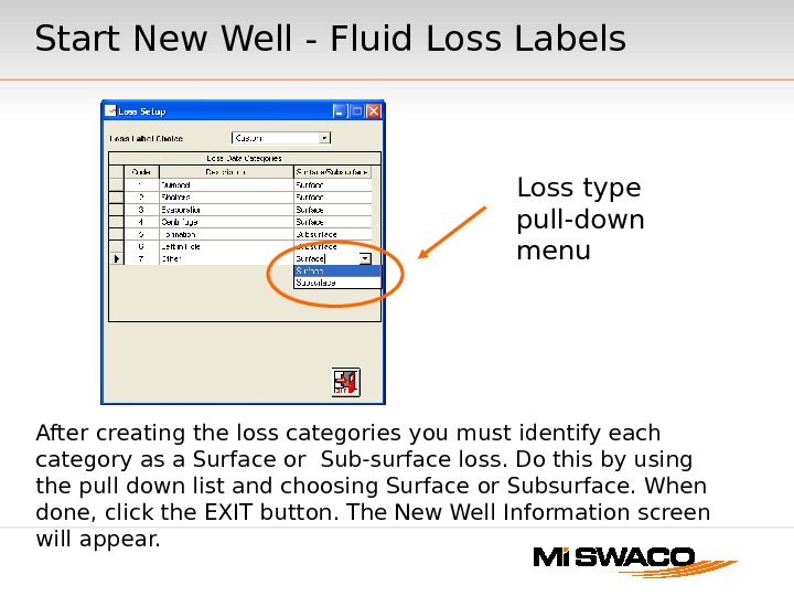
Loss type pull-down menu After creating the loss categories you must identify each category as a Surface or Sub-surface loss. Do this by using the pull down list and choosing Surface or Subsurface. When done, click the EXIT button. The New Well Information screen will appear. Start New Well — Fluid Loss Labels
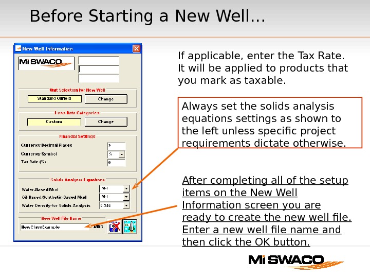
Before Starting a New Well. . . After completing all of the setup items on the New Well Information screen you are ready to create the new well file. Enter a new well file name and then click the OK button. Always set the solids analysis equations settings as shown to the left unless specific project requirements dictate otherwise. If applicable, enter the Tax Rate. It will be applied to products that you mark as taxable.
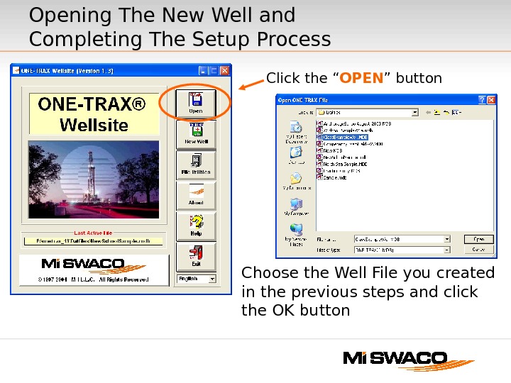
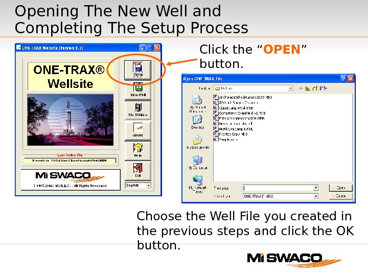
Opening The New Well and Completing The Setup Process Choose the Well File you created in the previous steps and click the OK button Click the “ OPEN ” button
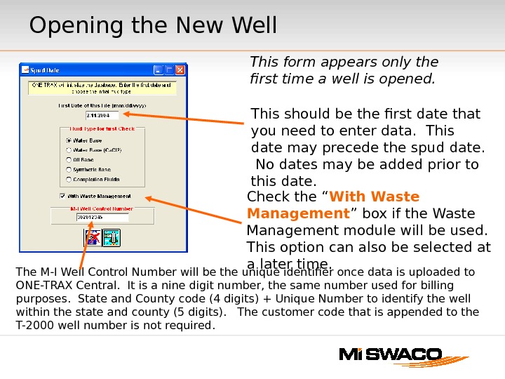
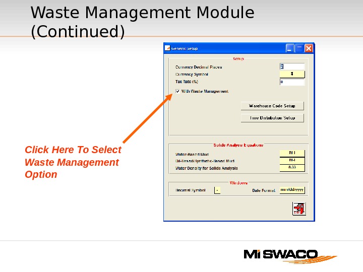
Opening the New Well The M-I Well Control Number will be the unique identifier once data is uploaded to ONE-TRAX Central. It is a nine digit number, the same number used for billing purposes. State and County code (4 digits) + Unique Number to identify the well within the state and county (5 digits). The customer code that is appended to the T-2000 well number is not required. This should be the first date that you need to enter data. This date may precede the spud date. No dates may be added prior to this date. This form appears only the first time a well is opened. Check the “ With Waste Management ” box if the Waste Management module will be used. This option can also be selected at a later time.
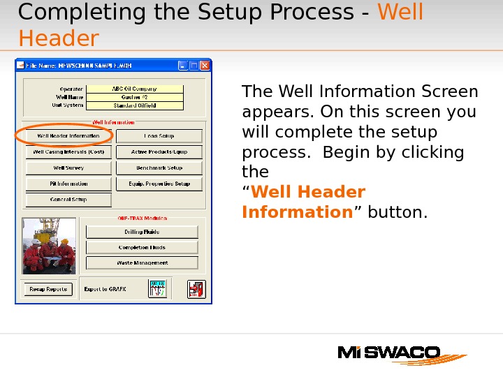
Completing the Setup Process — Well Header The Well Information Screen appears. On this screen you will complete the setup process. Begin by clicking the “ Well Header Information ” button.
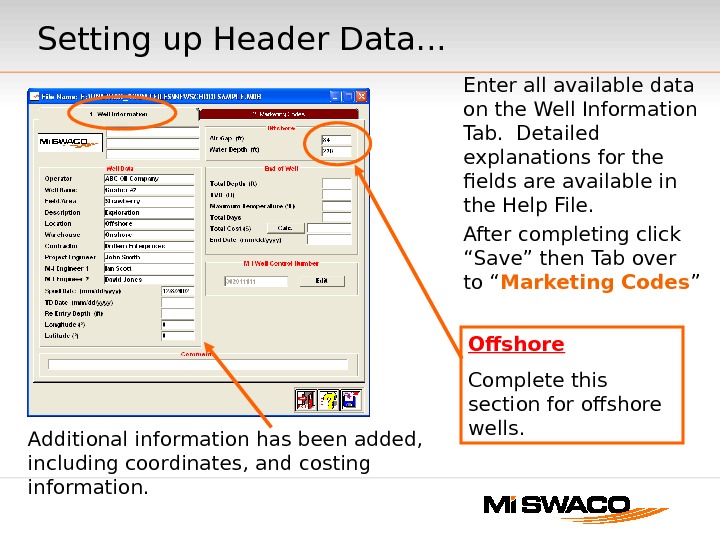
Enter all available data on the Well Information Tab. Detailed explanations for the fields are available in the Help File. After completing click “Save” then Tab over to “ Marketing Codes ” Additional information has been added, including coordinates, and costing information. Offshore Complete this section for offshore wells. Setting up Header Data. . .
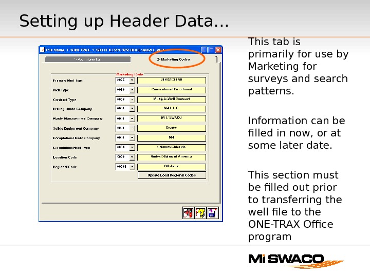
This tab is primarily for use by Marketing for surveys and search patterns. Information can be filled in now, or at some later date. This section must be filled out prior to transferring the well file to the ONE-TRAX Office program. Setting up Header Data. . .
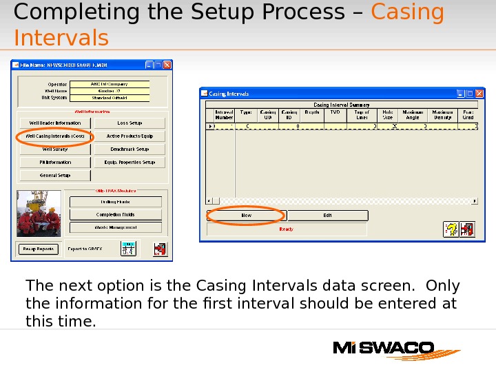
The next option is the Casing Intervals data screen. Only the information for the first interval should be entered at this time. Completing the Setup Process – Casing Intervals
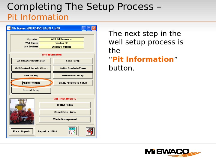
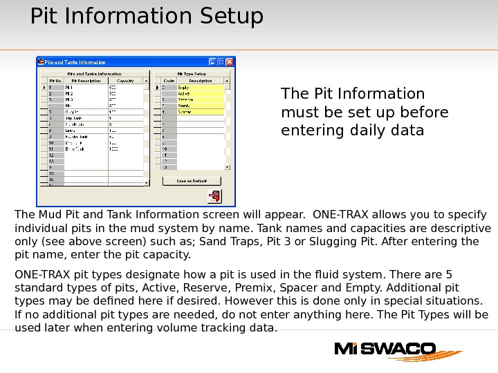
Completing The Setup Process – Pit Information The next step in the well setup process is the “ Pit Information ” button.
Pit Information Setup The Mud Pit and Tank Information screen will appear. ONE-TRAX allows you to specify individual pits in the mud system by name. Tank names and capacities are descriptive only (see above screen) such as; Sand Traps, Pit 3 or Slugging Pit. After entering the pit name, enter the pit capacity. ONE-TRAX pit types designate how a pit is used in the fluid system. There are 5 standard types of pits, Active, Reserve, Premix, Spacer and Empty. Additional pit types may be defined here if desired. However this is done only in special situations. If no additional pit types are needed, do not enter anything here. The Pit Types will be used later when entering volume tracking data. The Pit Information must be set up before entering daily data
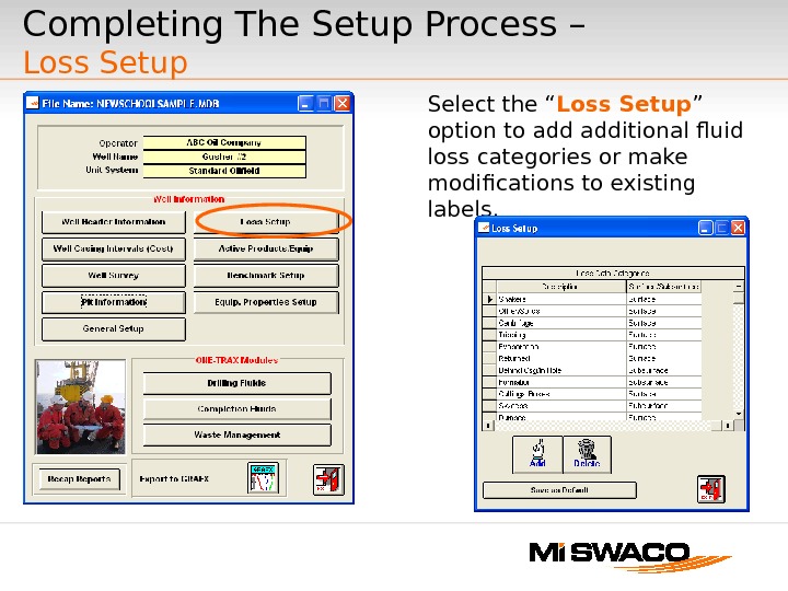
Completing The Setup Process – Loss Setup Select the “ Loss Setup ” option to additional fluid loss categories or make modifications to existing labels.
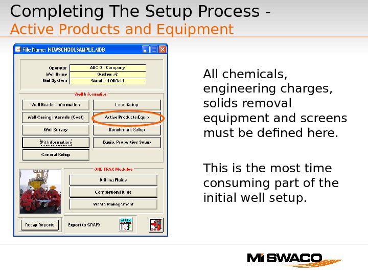
Completing The Setup Process — Active Products and Equipment All chemicals, engineering charges, solids removal equipment and screens must be defined here. This is the most time consuming part of the initial well setup.
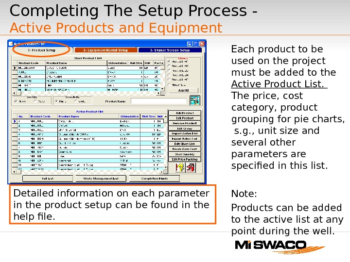
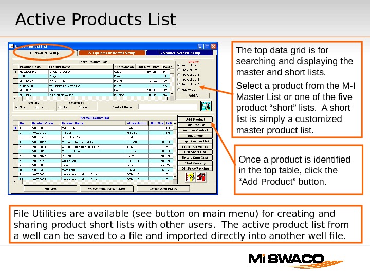
Each product to be used on the project must be added to the Active Product List. The price, cost category, product grouping for pie charts, s. g. , unit size and several other parameters are specified in this list. Note: Products can be added to the active list at any point during the well. Detailed information on each parameter in the product setup can be found in the help file. Completing The Setup Process — Active Products and Equipment
Active Products List File Utilities are available (see button on main menu) for creating and sharing product short lists with other users. The active product list from a well can be saved to a file and imported directly into another well file. The top data grid is for searching and displaying the master and short lists. Select a product from the M-I Master List or one of the five product “short” lists. A short list is simply a customized master product list. Once a product is identified in the top table, click the “Add Product” button.
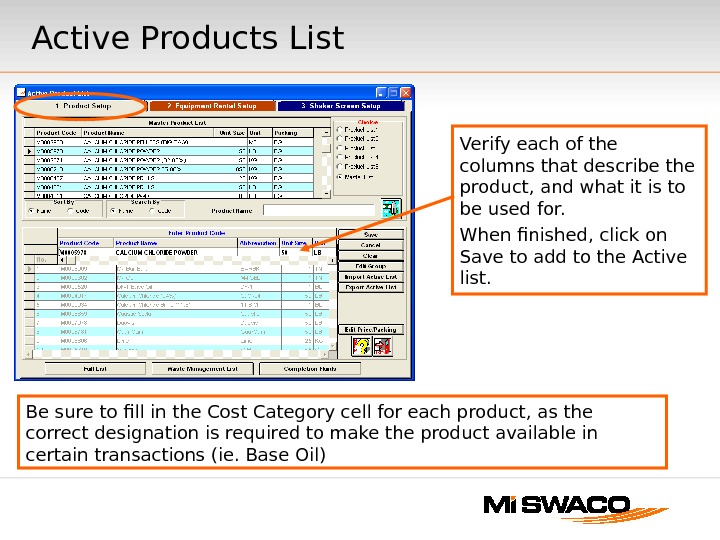
Active Products List Verify each of the columns that describe the product, and what it is to be used for. When finished, click on Save to add to the Active list. Be sure to fill in the Cost Category cell for each product, as the correct designation is required to make the product available in certain transactions (ie. Base Oil)
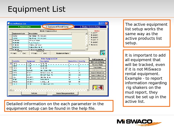
Equipment List The active equipment list setup works the same way as the active products list setup. It is important to add all equipment that will be tracked, even if it is not Mi. Swaco rental equipment. Example — to report information regarding rig shakers on the mud report, they must be set up in the active list. Detailed information on the each parameter in the equipment setup can be found in the help file.
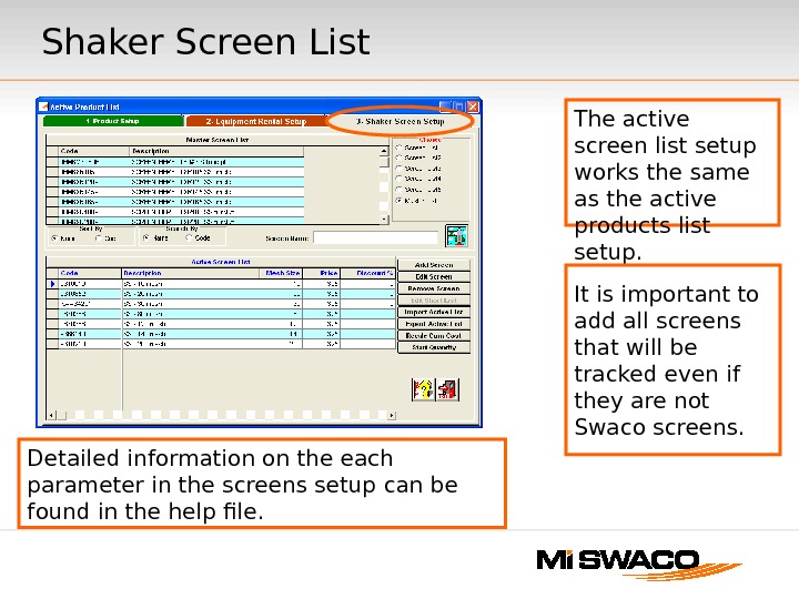
Shaker Screen List Detailed information on the each parameter in the screens setup can be found in the help file. The active screen list setup works the same as the active products list setup. It is important to add all screens that will be tracked even if they are not Swaco screens.
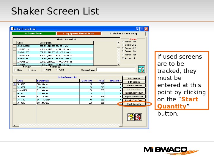
If used screens are to be tracked, they must be entered at this point by clicking on the “ Start Quantity ” button. Shaker Screen List
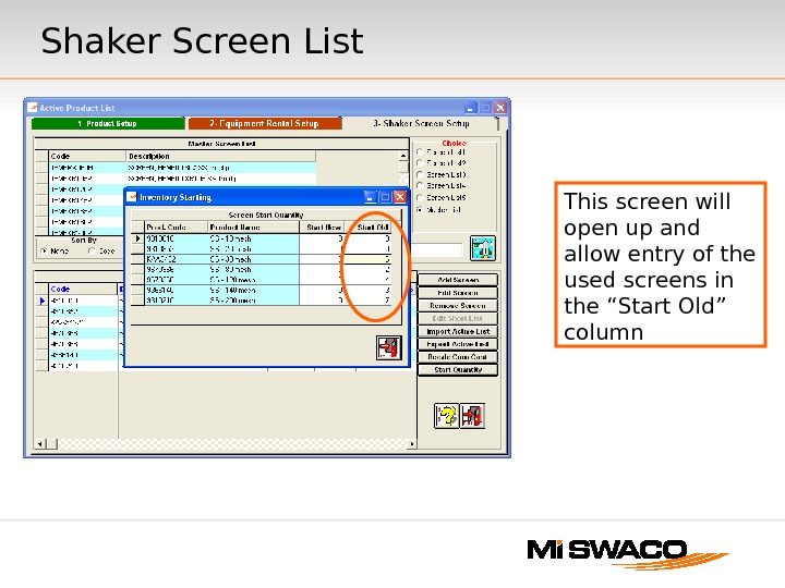
This screen will open up and allow entry of the used screens in the “Start Old” column Shaker Screen List
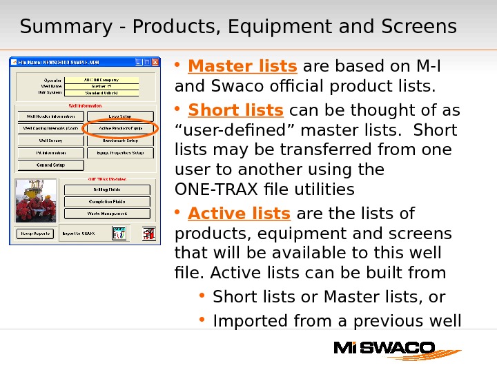
Summary — Products, Equipment and Screens Master lists are based on M-I and Swaco official product lists. Short lists can be thought of as “user-defined” master lists. Short lists may be transferred from one user to another using the ONE-TRAX file utilities Active lists are the lists of products, equipment and screens that will be available to this well file. Active lists can be built from Short lists or Master lists, or Imported from a previous well
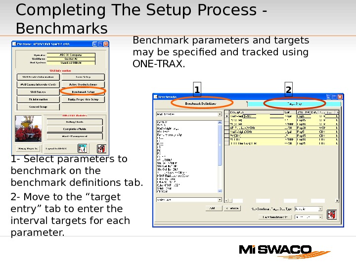
1 2 Completing The Setup Process — Benchmarks Benchmark parameters and targets may be specified and tracked using ONE-TRAX. 1 — Select parameters to benchmark on the benchmark definitions tab. 2 — Move to the “target entry” tab to enter the interval targets for each parameter.
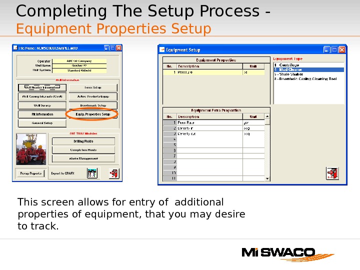
Completing The Setup Process — Equipment Properties Setup This screen allows for entry of additional properties of equipment, that you may desire to track.
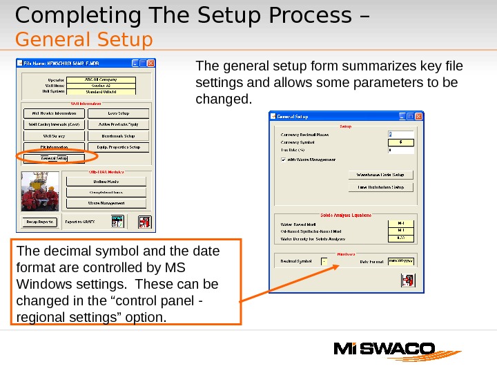
Completing The Setup Process – General Setup The general setup form summarizes key file settings and allows some parameters to be changed. The decimal symbol and the date format are controlled by MS Windows settings. These can be changed in the “control panel — regional settings” option.
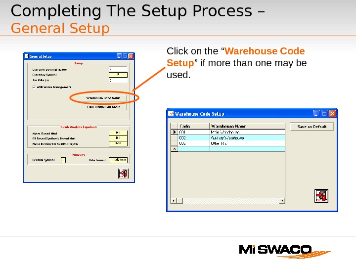
Click on the “ Warehouse Code Setup ” if more than one may be used. Completing The Setup Process – General Setup
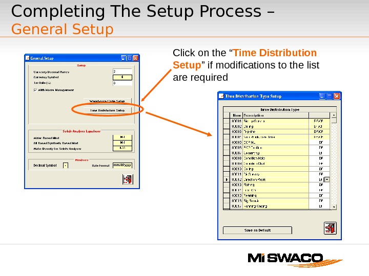
Click on the “ Time Distribution Setup ” if modifications to the list are required. Completing The Setup Process – General Setup
Why do we Benchmark? • Establish a standard • Measure Performance — Processes — Equipment — Products • Key Step in learning Process — Identify areas of Strength/Weakness — Assist in feedback to Planning — Assist in setting Technical limits • Identify Best-in-Class
What things do we Benchmark? • Comparison Level — $/ft, $/bbl hole — Bbl built/ft, Bbl built/bbl hole • Product/Service level — $ service/ft, $ service/bbl hole, $ service/day — Volume/ft, Volume/bbl hole, Amount product/unit volume drilled — Non-compliance incidents/day — Specific Process/ Equipment Note: Always know how to make a positive change in the benchmark!
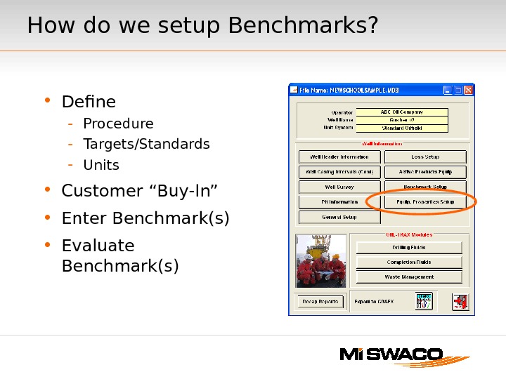
How do we setup Benchmarks? • Define — Procedure — Targets/Standards — Units • Customer “Buy-In” • Enter Benchmark(s) • Evaluate Benchmark(s)
• Benchmark Definition — Is everyone on the same page? — Look at hand-outs • Benchmark Targets — Do you know what values you are trying to achieve? • Feedback & Evaluation — View Daily Status — Affect Daily Status — Reporting Benchmark values — Reporting Target values. Mechanics of ONE-TRAX — Benchmark Feature
Reference Data & Tools • ONE-TRAX Help file • ONE-TRAX Set Up Form • ONE-TRAX Benchmark Definitions • IFE Product Planning Guide
ONE-TRAX ®® v 1. 3 Daily Input Procedures
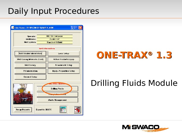
ONE-TRAX ®® 1. 3 Drilling Fluids Module. Daily Input Procedures
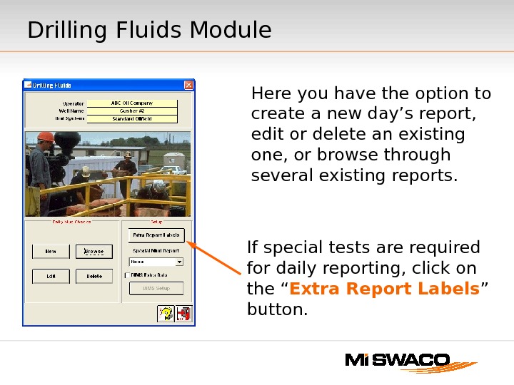
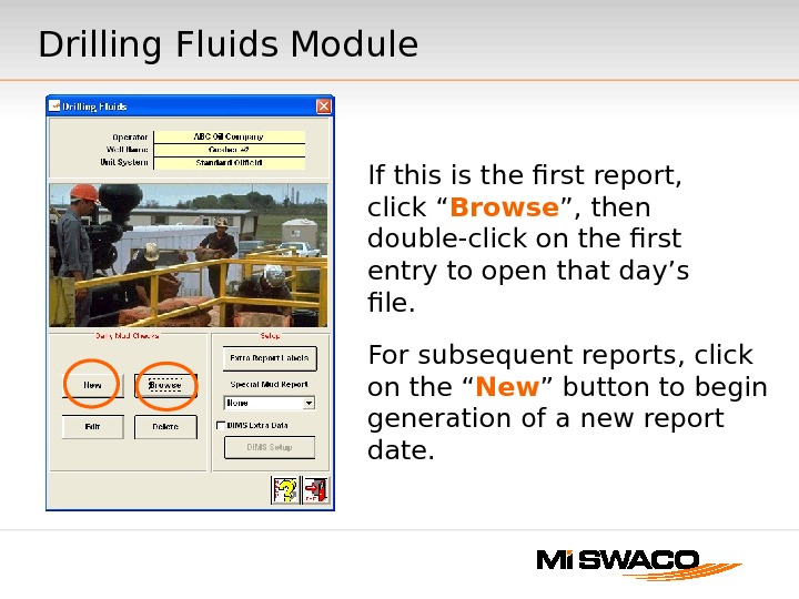
Drilling Fluids Module Here you have the option to create a new day’s report, edit or delete an existing one, or browse through several existing reports. If special tests are required for daily reporting, click on the “ Extra Report Labels ” button.
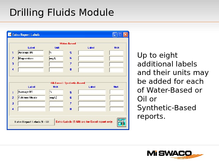
Up to eight additional labels and their units may be added for each of Water-Based or Oil or Synthetic-Based reports. Drilling Fluids Module
For subsequent reports, click on the “ New ” button to begin generation of a new report date. If this is the first report, click “ Browse ”, then double-click on the first entry to open that day’s file. Drilling Fluids Module
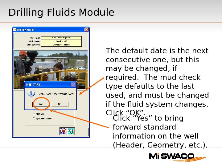
Drilling Fluids Module The default date is the next consecutive one, but this may be changed, if required. The mud check type defaults to the last used, and must be changed if the fluid system changes. Click “OK”. Click “Yes” to bring forward standard information on the well (Header, Geometry, etc. ).
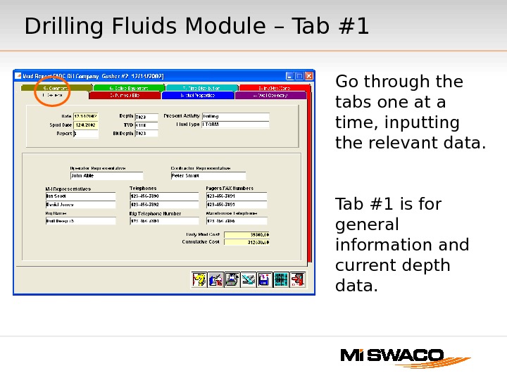
Go through the tabs one at a time, inputting the relevant data. Tab #1 is for general information and current depth data. Drilling Fluids Module – Tab #
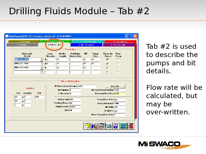
Tab #2 is used to describe the pumps and bit details. Flow rate will be calculated, but may be over-written. Drilling Fluids Module – Tab #
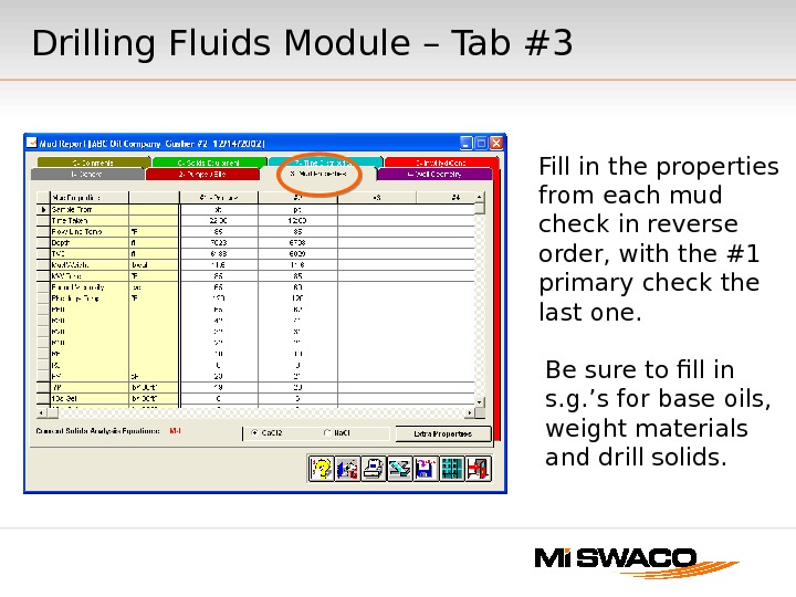
Fill in the properties from each mud check in reverse order, with the #1 primary check the last one. Be sure to fill in s. g. ’s for base oils, weight materials and drill solids. Drilling Fluids Module – Tab #
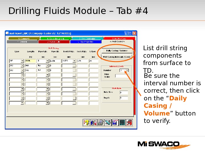
List drill string components from surface to TD. Be sure the interval number is correct, then click on the “ Daily Casing / Volume ” button to verify. Drilling Fluids Module – Tab #
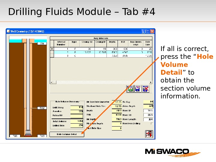
If all is correct, press the “ Hole Volume Detail ” to obtain the section volume information. Drilling Fluids Module – Tab #
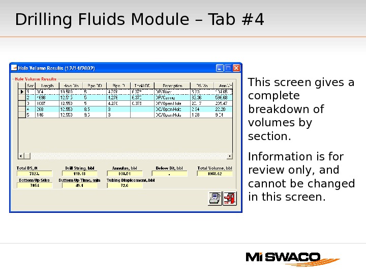
This screen gives a complete breakdown of volumes by section. Information is for review only, and cannot be changed in this screen. Drilling Fluids Module – Tab #
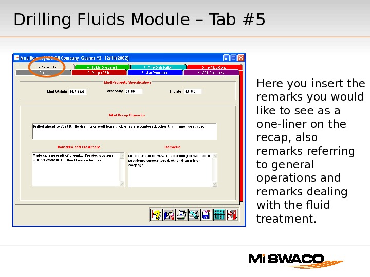
Here you insert the remarks you would like to see as a one-liner on the recap, also remarks referring to general operations and remarks dealing with the fluid treatment. Drilling Fluids Module – Tab #
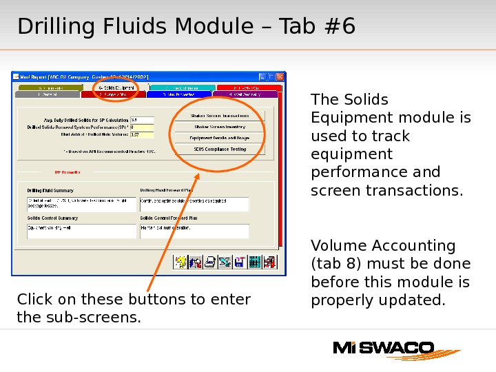
The Solids Equipment module is used to track equipment performance and screen transactions. Volume Accounting (tab 8) must be done before this module is properly updated. Click on these buttons to enter the sub-screens. Drilling Fluids Module – Tab #
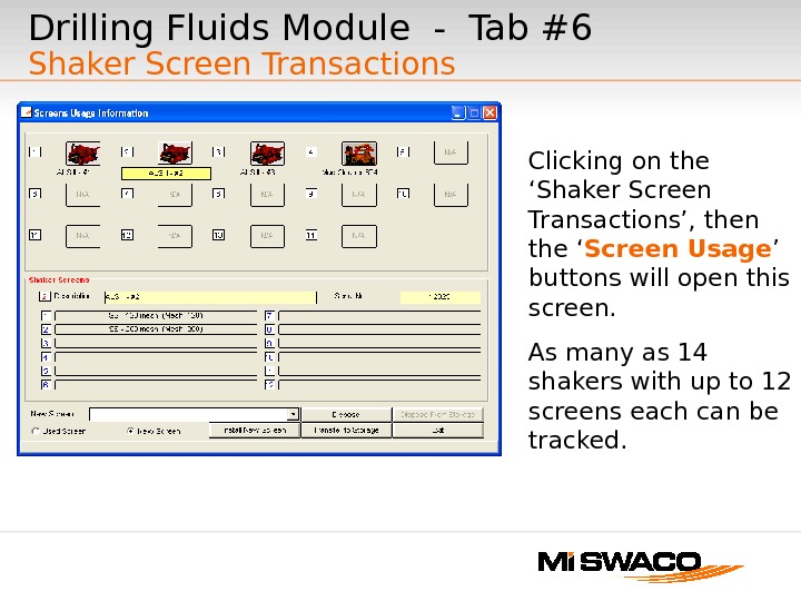
Drilling Fluids Module — Tab #6 Shaker Screen Transactions Clicking on the ‘Shaker Screen Transactions’, then the ‘ Screen Usage ’ buttons will open this screen. As many as 14 shakers with up to 12 screens each can be tracked.
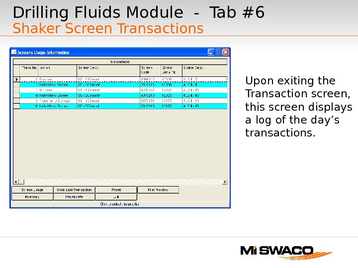
Upon exiting the Transaction screen, this screen displays a log of the day’s transactions. Drilling Fluids Module — Tab #6 Shaker Screen Transactions
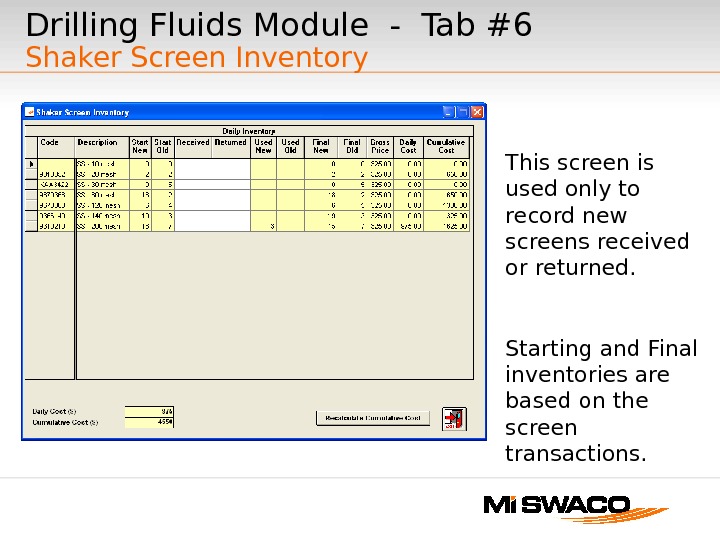
This screen is used only to record new screens received or returned. Starting and Final inventories are based on the screen transactions. Drilling Fluids Module — Tab #6 Shaker Screen Inventory
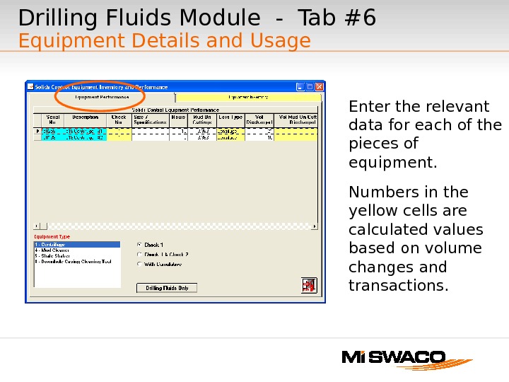
Drilling Fluids Module — Tab #6 Equipment Details and Usage Enter the relevant data for each of the pieces of equipment. Numbers in the yellow cells are calculated values based on volume changes and transactions.
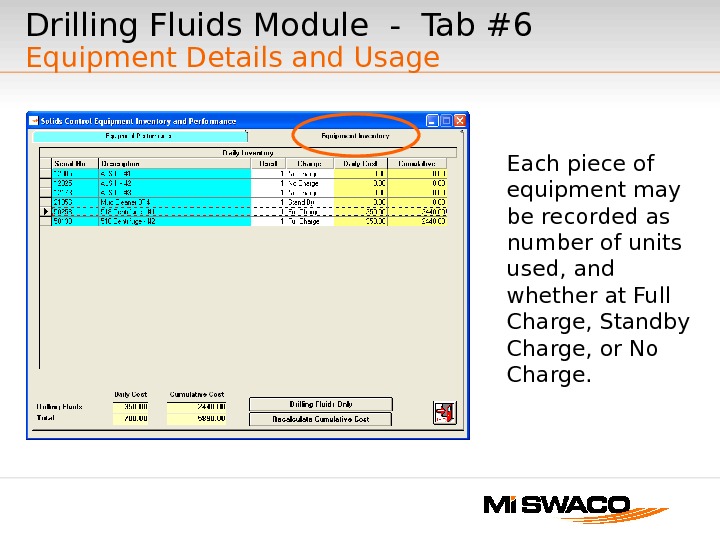
Each piece of equipment may be recorded as number of units used, and whether at Full Charge, Standby Charge, or No Charge. Drilling Fluids Module — Tab #6 Equipment Details and Usage
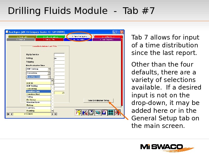
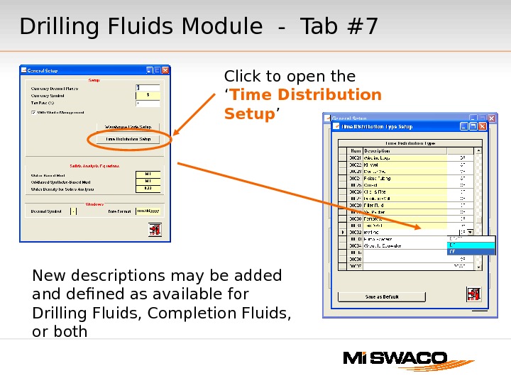
Drilling Fluids Module — Tab #7 Tab 7 allows for input of a time distribution since the last report. Other than the four defaults, there a variety of selections available. If a desired input is not on the drop-down, it may be added here or in the General Setup tab on the main screen.
Drilling Fluids Module — Tab #7 Click to open the ‘ Time Distribution Setup ’ New descriptions may be added and defined as available for Drilling Fluids, Completion Fluids, or both
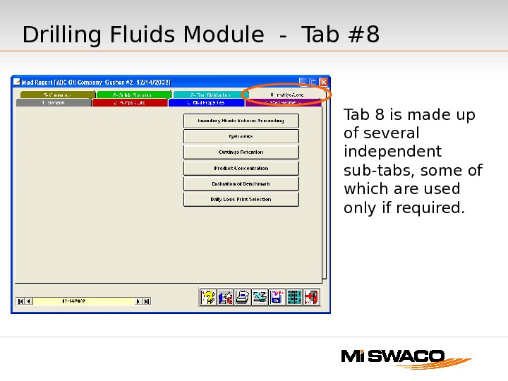
Tab 8 is made up of several independent sub-tabs, some of which are used only if required. Drilling Fluids Module — Tab #
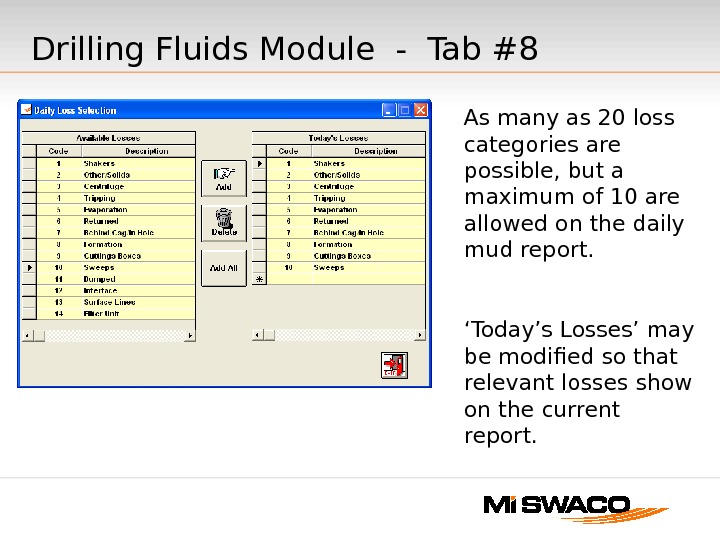
As many as 20 loss categories are possible, but a maximum of 10 are allowed on the daily mud report. ‘ Today’s Losses’ may be modified so that relevant losses show on the current report. Drilling Fluids Module — Tab #
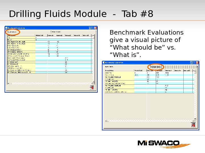
Benchmark Evaluations give a visual picture of “What should be” vs. “What is”. Drilling Fluids Module — Tab #
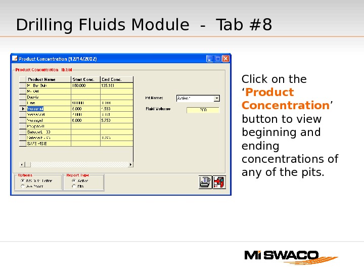
Click on the ‘ Product Concentration ’ button to view beginning and ending concentrations of any of the pits. Drilling Fluids Module — Tab #
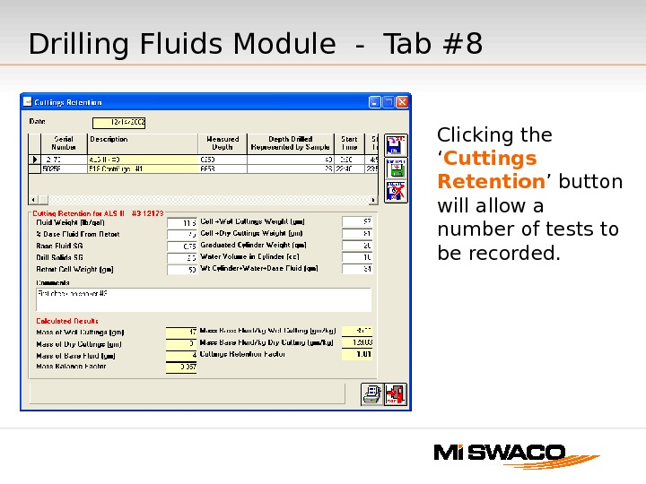
Clicking the ‘ Cuttings Retention ’ button will allow a number of tests to be recorded. Drilling Fluids Module — Tab #
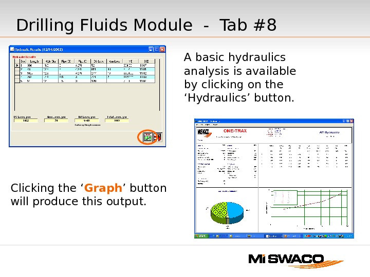
A basic hydraulics analysis is available by clicking on the ‘Hydraulics’ button. Clicking the ‘ Graph ’ button will produce this output. Drilling Fluids Module — Tab #
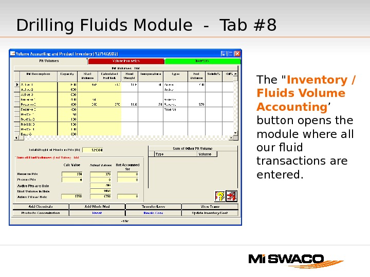
The » Inventory / Fluids Volume Accounting ’ button opens the module where all our fluid transactions are entered. Drilling Fluids Module — Tab #
Volume Accounting Illustrated instructions on the use of ONE-TRAX ® v 1. 3 Volume Accounting
Using this Presentation This presentation assumes you are familiar with the basics of setting up a well in ONE-TRAX and addresses only the volume accounting section of the software. Since this portion deals only with volume accounting, it does not describe all of the steps needed to complete a ONE-TRAX daily report. When entering daily mud check data into ONE-TRAX, it is important to complete all relevant steps and enter data in the order of the tabs. In other words, begin with tab 1 — “General” and end with tab 8 -”Calc/Pits/Inventory”. One exception is to leave tab 6 for last, since it requires data from ‘volume accounting’ to complete its calculations. (Pretend this is tab 9).
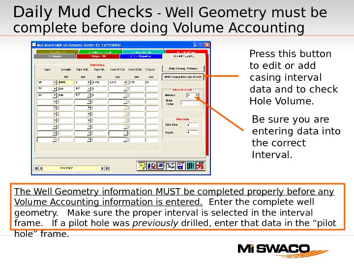
Daily Mud Checks — Well Geometry must be complete before doing Volume Accounting The Well Geometry information MUST be completed properly before any Volume Accounting information is entered. Enter the complete well geometry. Make sure the proper interval is selected in the interval frame. If a pilot hole was previously drilled, enter that data in the “pilot hole” frame. Press this button to edit or add casing interval data and to check Hole Volume. Be sure you are entering data into the correct Interval.
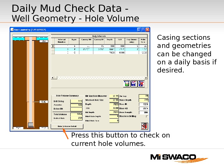
Daily Mud Check Data — Well Geometry — Hole Volume Casing sections and geometries can be changed on a daily basis if desired. Press this button to check on current hole volumes.
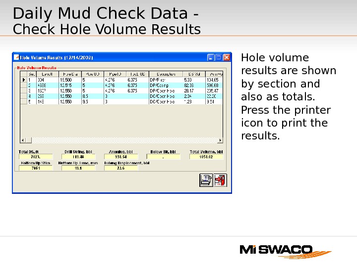
Daily Mud Check Data — Check Hole Volume Results Hole volume results are shown by section and also as totals. Press the printer icon to print the results.
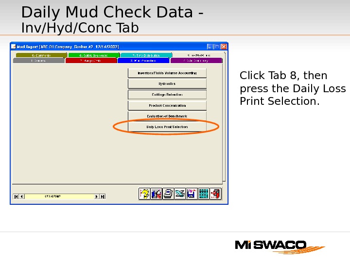
Daily Mud Check Data — Inv/Hyd/Conc Tab Click Tab 8, then press the Daily Loss Print Selection.
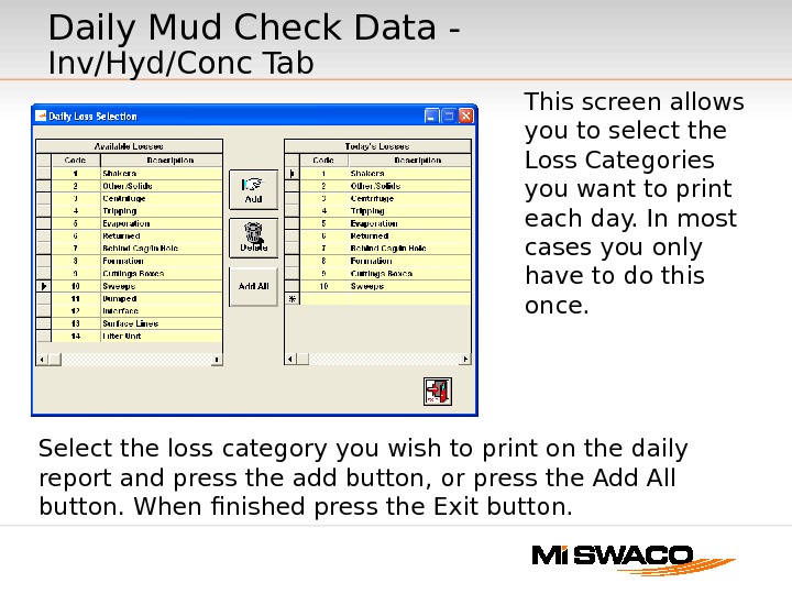
Select the loss category you wish to print on the daily report and press the add button, or press the Add All button. When finished press the Exit button. This screen allows you to select the Loss Categories you want to print each day. In most cases you only have to do this once. Daily Mud Check Data — Inv/Hyd/Conc Tab
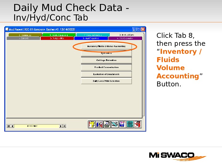
Click Tab 8, then press the “ Inventory / Fluids Volume Accounting ” Button. Daily Mud Check Data — Inv/Hyd/Conc Tab
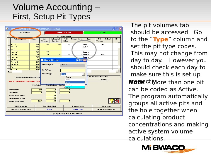
Volume Accounting – First, Setup Pit Types The pit volumes tab should be accessed. Go to the “ Type ” column and set the pit type codes. This may not change from day to day. However you should check each day to make sure this is set up correctly. Note : — More than one pit can be coded as Active. The program automatically groups all active pits and the hole together when calculating product concentrations and making active system volume calculations.
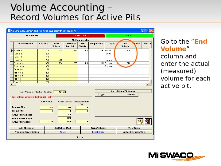
Go to the “ End Volume ” column and enter the actual (measured) volume for each active pit. Volume Accounting – Record Volumes for Active Pits
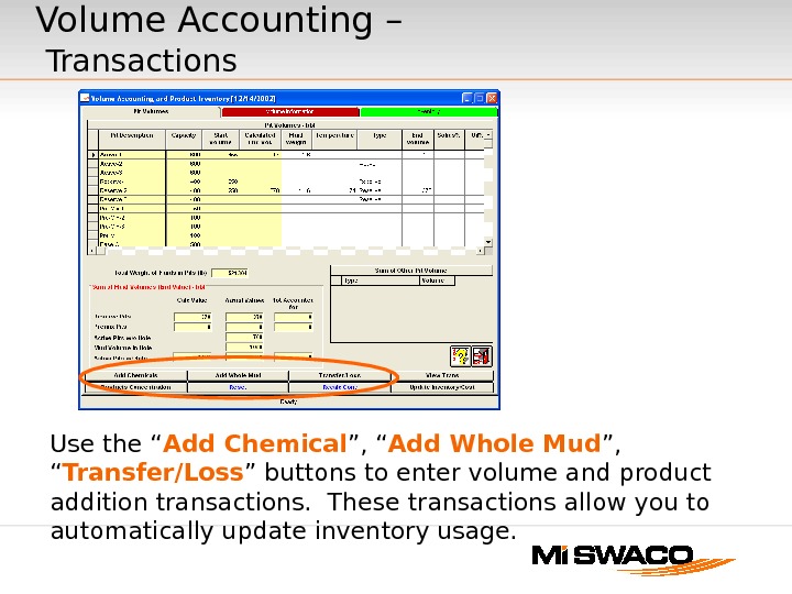
Use the “ Add Chemical ”, “ Add Whole Mud ”, “ Transfer/Loss ” buttons to enter volume and product addition transactions. These transactions allow you to automatically update inventory usage. Volume Accounting – Transactions
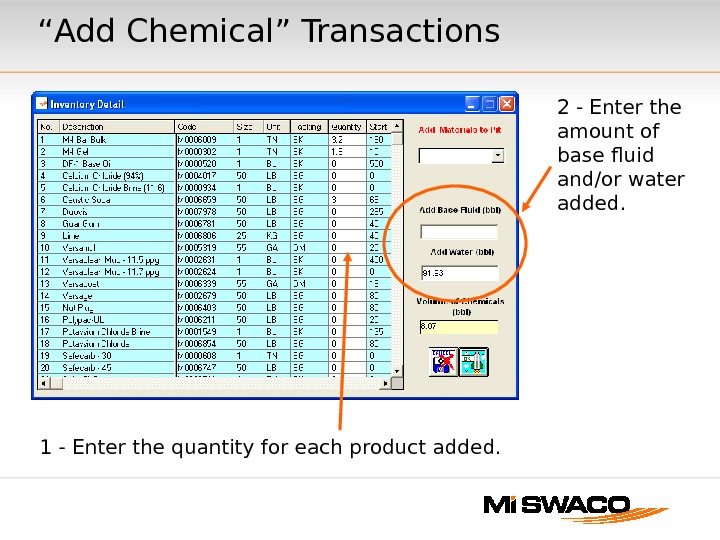
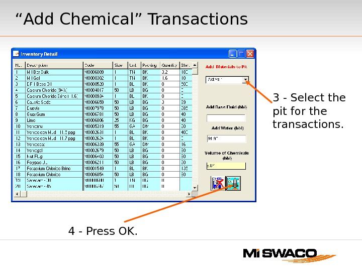
“ Add Chemical” Transactions 1 — Enter the quantity for each product added. 2 — Enter the amount of base fluid and/or water added.
4 — Press OK. 3 — Select the pit for the transactions. “ Add Chemical” Transactions
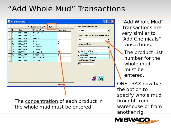
“ Add Whole Mud” Transactions The product List number for the whole mud must be entered. “ Add Whole Mud” transactions are very similar to “Add Chemicals” transactions. The concentration of each product in the whole mud must be entered. ONE-TRAX now has the option to specify whole mud brought from warehouse or from another rig.
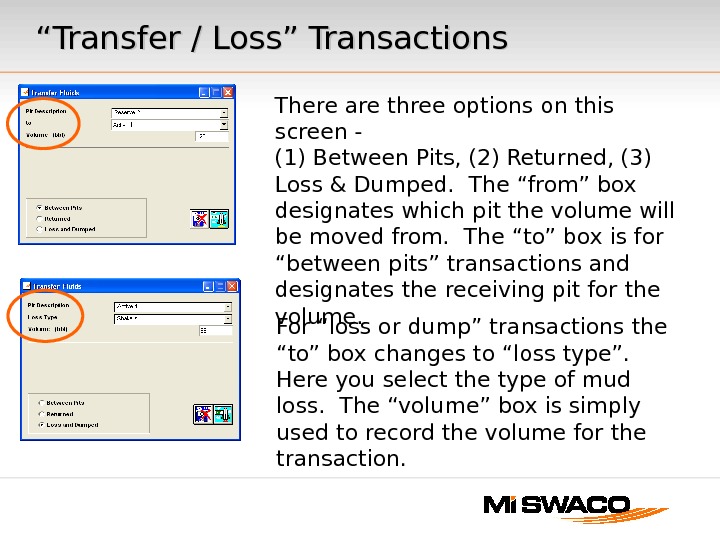
““ Transfer / Loss” Transactions There are three options on this screen — (1) Between Pits, (2) Returned, (3) Loss & Dumped. The “from” box designates which pit the volume will be moved from. The “to” box is for “between pits” transactions and designates the receiving pit for the volume. For “loss or dump” transactions the “to” box changes to “loss type”. Here you select the type of mud loss. The “volume” box is simply used to record the volume for the transaction.
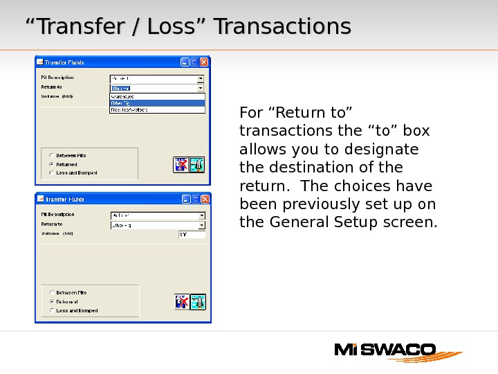
““ Transfer / Loss” Transactions For “Return to” transactions the “to” box allows you to designate the destination of the return. The choices have been previously set up on the General Setup screen.
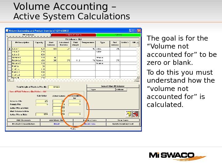
Volume Accounting – Active System Calculations The goal is for the “Volume not accounted for” to be zero or blank. To do this you must understand how the “volume not accounted for” is calculated.
Definitions — Active System Calculations “ Volume not accounted for” = (active Calc end volume with hole) — (active Actual end volume with hole). The goal is to make the calculated volume match the actual volume. “ Active Calc end volume with hole” — this number is theoretical active system volume based on the transactions entered. “ Active Actual end volume with hole” — this is the sum of the measured active pit volumes entered and the hole volume. If the pit volumes were entered correctly this is the actual circulating volume.
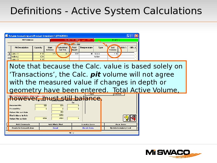
Definitions — Active System Calculations Note that because the Calc. value is based solely on ‘Transactions’, the Calc. pit volume will not agree with the measured value if changes in depth or geometry have been entered. Total Active Volume, however, must still balance.
Using the Volume Not Accounted For Calculation If the “end volume” for each active pit is correct and ALL product and volume additions to the active system have been made “volume not accounted for” will be positive. This number is the amount of mud loss (or mud transfers) volume that needs to entered. Use the “transfer/loss” transactions to record these volumes. Many engineers use this number to determine the correct losses to enter each day. If the “end volume” for each active pit is correct and “volume not accounted for” is negative this means that not all of the product and volume addition transactions have been recorded. If “volume not accounted for” is blank or zero, everything balances. If the “end volume” for each active pit is not correct, or the well geometry is not correct, the “volume not accounted for” will show a number. It may be either positive or negative depending on the errors made.
Volume Accounting — Changing Systems Dumping the entire active system — This is done by entering one or more “transfer/loss” transactions using the “loss / dumped” option. For each active pit enter a “loss” transaction equal to the volume for that pit. Next enter a “loss” transaction equal to the hole volume using one of the active pits in the transfer mud “from” box. Transferring or returning the entire active system — The same process as dumping, except use the “between pit” or “return” types of “transfer/loss” transactions. Transactions to record added volume for the new system — Use the “add chemicals” or “add whole mud” transactions to record the volume of new mud added. These transactions will be made to “active pits”. When adding volume to an active pit it is OK if the volume added is greater than the designated capacity of the pit. Remember ONE-TRAX treats the hole volume and active pits all as one active system. It is important to remember that the volume needed to fill the hole must be included in these transactions. After all transactions are complete make sure that you have the correct number entered for “end volumes” on the “pit volumes” tab.
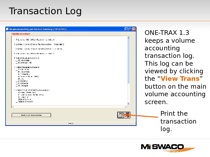
Transaction Log ONE-TRAX 1. 3 keeps a volume accounting transaction log. This log can be viewed by clicking the “ View Trans ” button on the main volume accounting screen. Print the transaction log.
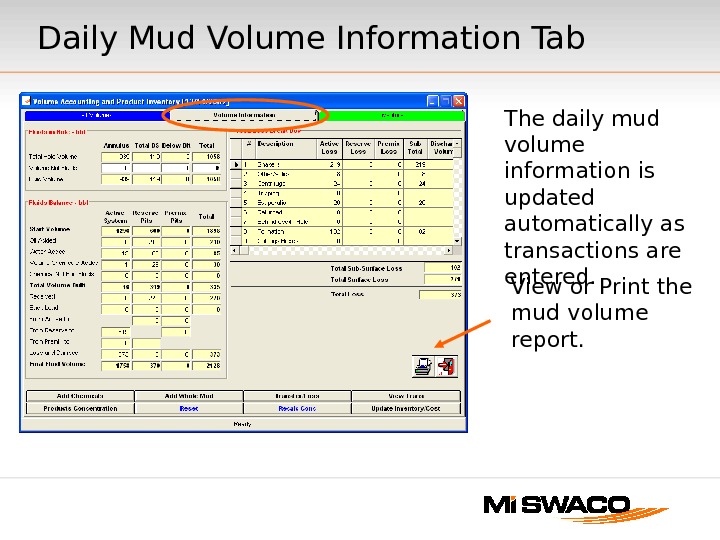
Daily Mud Volume Information Tab View or Print the mud volume report. The daily mud volume information is updated automatically as transactions are entered.
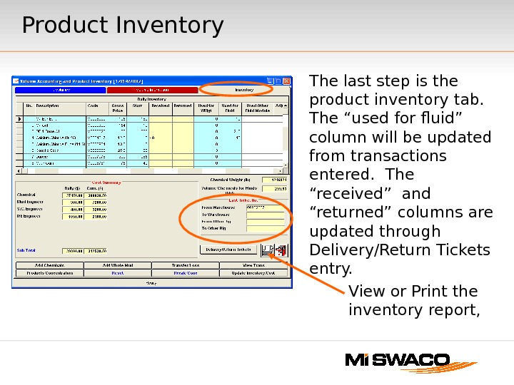
Product Inventory The last step is the product inventory tab. The “used for fluid” column will be updated from transactions entered. The “received” and “returned” columns are updated through Delivery/Return Tickets entry. View or Print the inventory report,
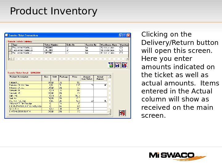
Clicking on the Delivery/Return button will open this screen. Here you enter amounts indicated on the ticket as well as actual amounts. Items entered in the Actual column will show as received on the main screen. Product Inventory
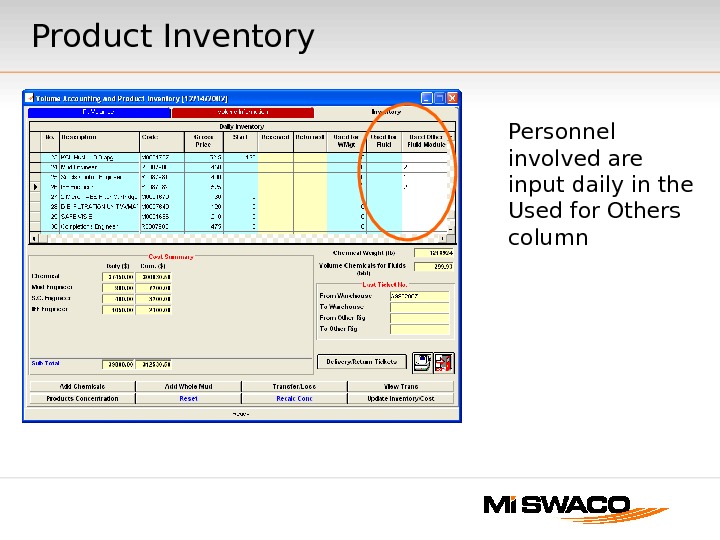
Personnel involved are input daily in the Used for Others column. Product Inventory
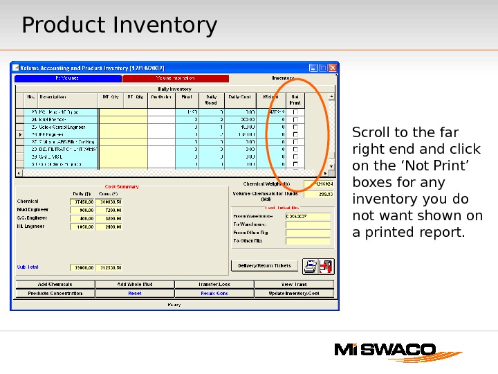
Scroll to the far right end and click on the ‘Not Print’ boxes for any inventory you do not want shown on a printed report. Product Inventory
This page is intentionally left blank
ONE-TRAX ®® 1. 3 Completion Fluids Module Illustrated instructions on using ONE-TRAX for Completion Fluids Reporting
To Start a new well. . . Click on the “ New Well ” button.
Start New Well — Engineering Units the engineering units setup must be selected before the new well file is created. it can not be changed after the new well file is started. Click the Unit Selection “ Change ” button.
Ten pre-defined unit sets are available. A custom unit set can also be defined and selected. Start New Well — Engineering Units
The New Well Information Screen will appear. You must setup the Loss Data Categories as part of the well setup. These categories are used to account for completion fluid losses during the well. Click the Loss Data Category “ Change ” button. Start New Well – Fluid Loss Labels
The loss setup screen will appear. On this screen you can choose from a set of standard mud loss categories or create a custom set. These labels can be edited during the well if needed. Note that if you choose a standard set of loss labels the labels highlighted in yellow cannot be changed. If you need the ability to edit all the labels choose a custom label set. Start New Well – Fluid Loss Labels
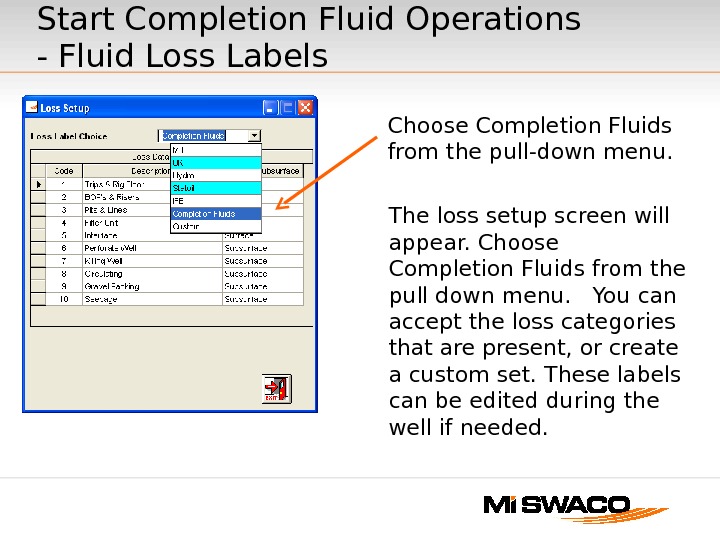
The loss setup screen will appear. Choose Completion Fluids from the pull down menu. You can accept the loss categories that are present, or create a custom set. These labels can be edited during the well if needed. Start Completion Fluid Operations — Fluid Loss Labels Choose Completion Fluids from the pull-down menu.
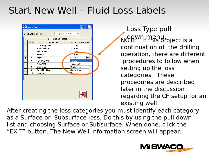
After creating the loss categories you must identify each category as a Surface or Subsurface loss. Do this by using the pull down list and choosing Surface or Subsurface. When done, click the “EXIT” button. The New Well Information screen will appear. Loss Type pull down menu. NOTE: If this project is a continuation of the drilling operation, there are different procedures to follow when setting up the loss categories. These procedures are described later in the discussion regarding the CF setup for an existing well. Start New Well – Fluid Loss Labels
Opening The New Well and Completing The Setup Process Choose the Well File you created in the previous steps and click the OK button. Click the “ OPEN ” button.
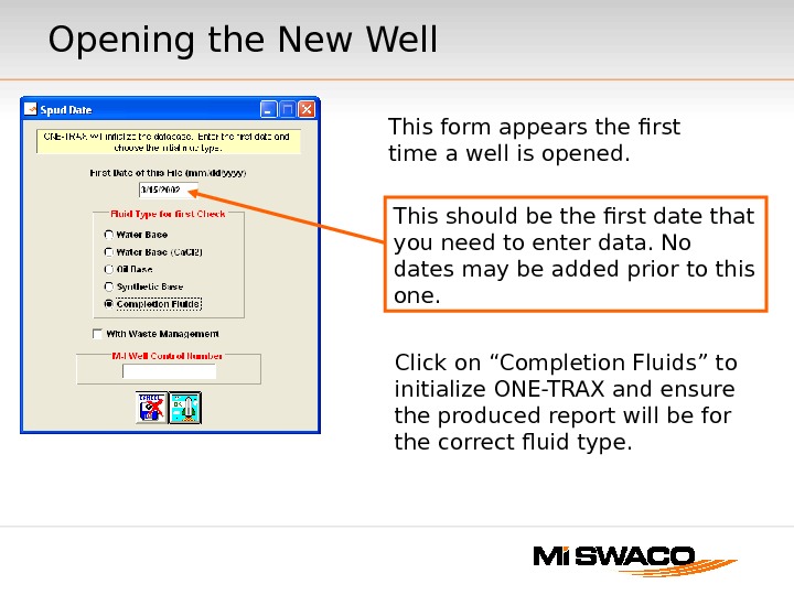
Opening the New Well This should be the first date that you need to enter data. No dates may be added prior to this one. This form appears the first time a well is opened. Click on “Completion Fluids” to initialize ONE-TRAX and ensure the produced report will be for the correct fluid type.
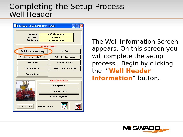
Completing the Setup Process – Well Header The Well Information Screen appears. On this screen you will complete the setup process. Begin by clicking the “ Well Header Information ” button.
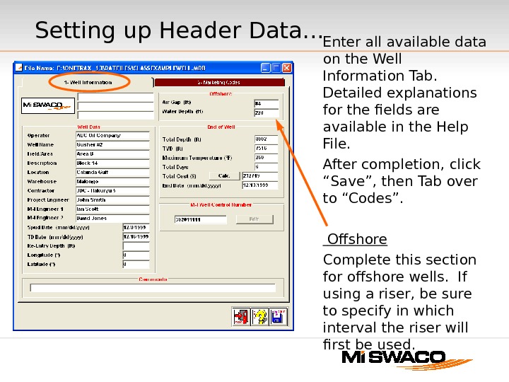
Setting up Header Data. . . Enter all available data on the Well Information Tab. Detailed explanations for the fields are available in the Help File. After completion, click “Save”, then Tab over to “Codes”. Offshore Complete this section for offshore wells. If using a riser, be sure to specify in which interval the riser will first be used.
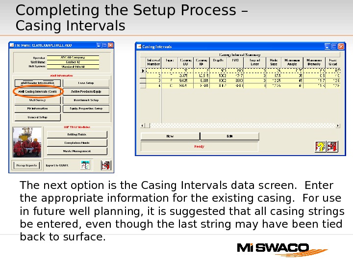
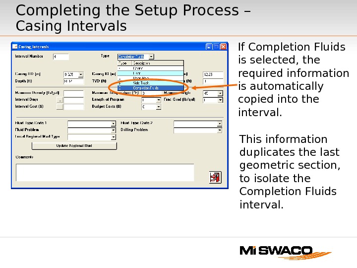
The next option is the Casing Intervals data screen. Enter the appropriate information for the existing casing. For use in future well planning, it is suggested that all casing strings be entered, even though the last string may have been tied back to surface. Completing the Setup Process – Casing Intervals
If Completion Fluids is selected, the required information is automatically copied into the interval. Completing the Setup Process – Casing Intervals This information duplicates the last geometric section, to isolate the Completion Fluids interval.
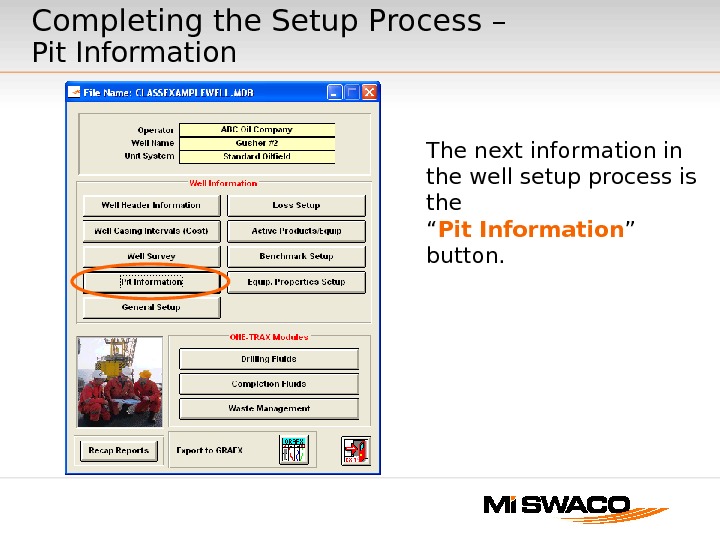
The next information in the well setup process is the “ Pit Information ” button. Completing the Setup Process – Pit Information
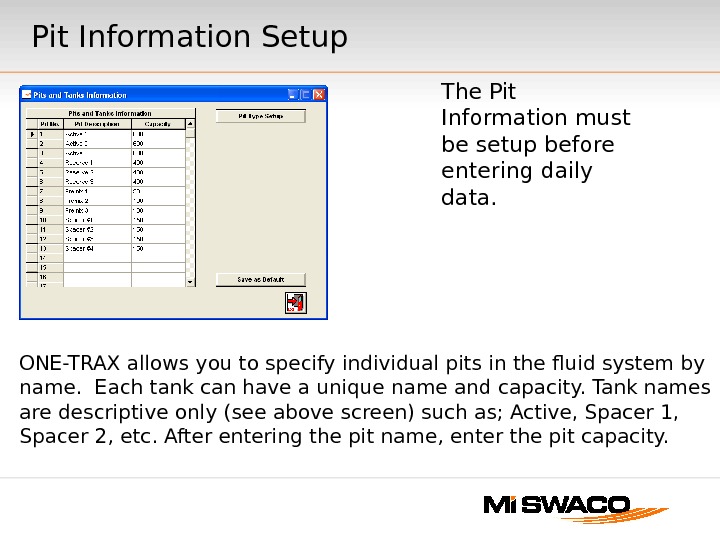
ONE-TRAX allows you to specify individual pits in the fluid system by name. Each tank can have a unique name and capacity. Tank names are descriptive only (see above screen) such as; Active, Spacer 1, Spacer 2, etc. After entering the pit name, enter the pit capacity. The Pit Information must be setup before entering daily data. Pit Information Setup
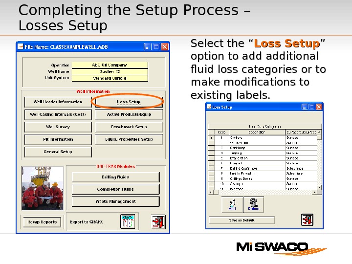
Select the “ Loss Setup ” ” option to add additional fluid loss categories or to make modifications to existing labels. Completing the Setup Process – Losses Setup
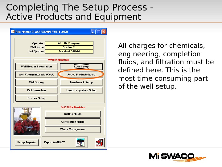
Completing The Setup Process — Active Products and Equipment All charges for chemicals, engineering, completion fluids, and filtration must be defined here. This is the most time consuming part of the well setup.
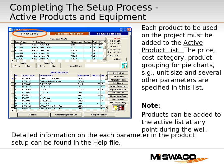
Completing The Setup Process — Active Products and Equipment Each product to be used on the project must be added to the Active Product List. The price, cost category, product grouping for pie charts, s. g. , unit size and several other parameters are specified in this list. Note : Products can be added to the active list at any point during the well. Detailed information on the each parameter in the product setup can be found in the Help file.
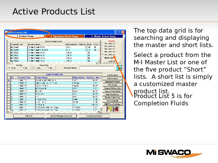
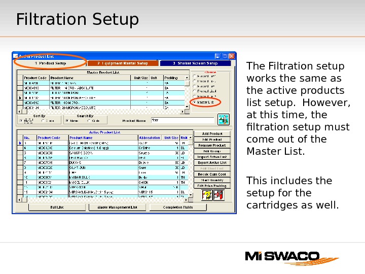
Active Products List The top data grid is for searching and displaying the master and short lists. Select a product from the M-I Master List or one of the five product “Short” lists. A short list is simply a customized master product list. Product List 5 is for Completion Fluids
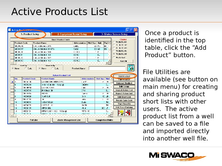
Active Products List File Utilities are available (see button on main menu) for creating and sharing product short lists with other users. The active product list from a well can be saved to a file and imported directly into another well file. Once a product is identified in the top table, click the “Add Product” button.
Filtration Setup The Filtration setup works the same as the active products list setup. However, at this time, the filtration setup must come out of the Master List. This includes the setup for the cartridges as well.
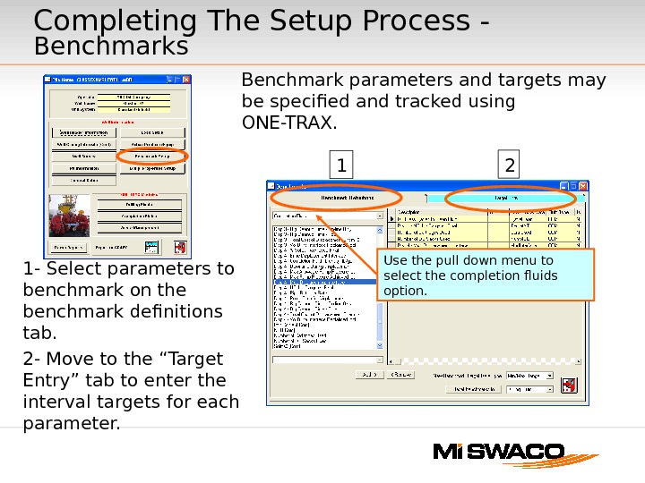
Benchmark parameters and targets may be specified and tracked using ONE-TRAX. 1 — Select parameters to benchmark on the benchmark definitions tab. 2 — Move to the “Target Entry” tab to enter the interval targets for each parameter. 1 2 Use the pull down menu to select the completion fluids option. Completing The Setup Process — Benchmarks
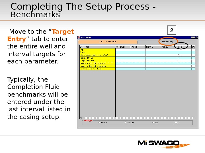
Move to the “ Target Entry ” tab to enter the entire well and interval targets for each parameter. Typically, the Completion Fluid benchmarks will be entered under the last interval listed in the casing setup. 2 Completing The Setup Process — Benchmarks
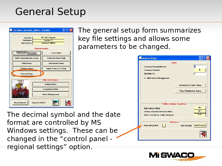
General Setup The general setup form summarizes key file settings and allows some parameters to be changed. The decimal symbol and the date format are controlled by MS Windows settings. These can be changed in the “control panel — regional settings” option.
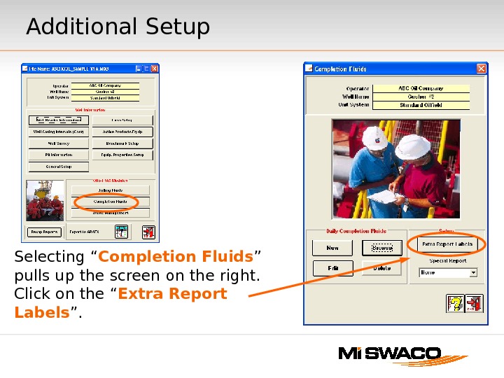
Additional Setup Selecting “ Completion Fluids ” pulls up the screen on the right. Click on the “ Extra Report Labels ”.
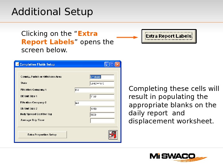
Completing these cells will result in populating the appropriate blanks on the daily report and displacement worksheet. Clicking on the “ Extra Report Labels ” opens the screen below. Additional Setup
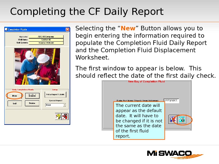
Completing the CF Daily Report Selecting the “ New ” Button allows you to begin entering the information required to populate the Completion Fluid Daily Report and the Completion Fluid Displacement Worksheet. The first window to appear is below. This should reflect the date of the first daily check. The current date will appear as the default date. It will have to be changed if it is not the same as the date of the first fluid report.
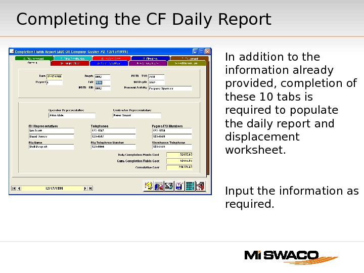
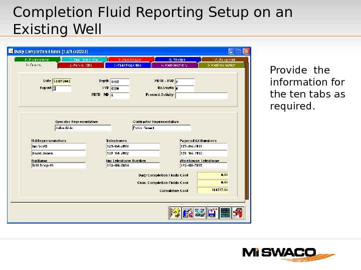
In addition to the information already provided, completion of these 10 tabs is required to populate the daily report and displacement worksheet. Input the information as required. Completing the CF Daily Report
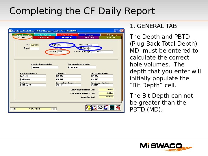
1. GENERAL TAB The Depth and PBTD (Plug Back Total Depth) MD must be entered to calculate the correct hole volumes. The depth that you enter will initially populate the “Bit Depth” cell. The Bit Depth can not be greater than the PBTD (MD). Completing the CF Daily Report
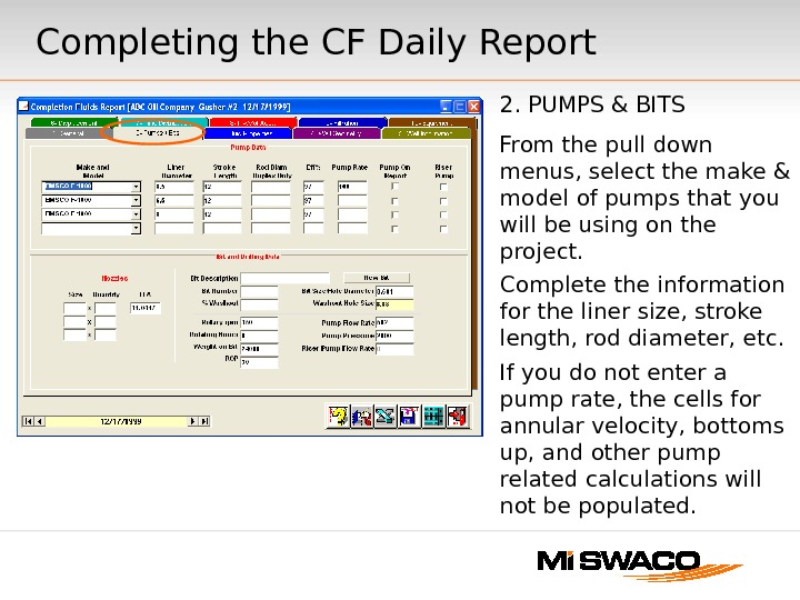
2. PUMPS & BITS From the pull down menus, select the make & model of pumps that you will be using on the project. Complete the information for the liner size, stroke length, rod diameter, etc. If you do not enter a pump rate, the cells for annular velocity, bottoms up, and other pump related calculations will not be populated. Completing the CF Daily Report
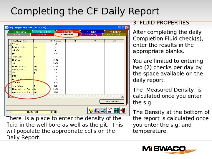
3. FLUID PROPERTIES After completing the daily Completion Fluid check(s), enter the results in the appropriate blanks. You are limited to entering two (2) checks per day by the space available on the daily report. The Measured Density is calculated once you enter the s. g. The Density at the bottom of the report is calculated once you enter the s. g. and temperature. There is a place to enter the density of the fluid in the well bore as well as the pit. This will populate the appropriate cells on the Daily Report. Completing the CF Daily Report
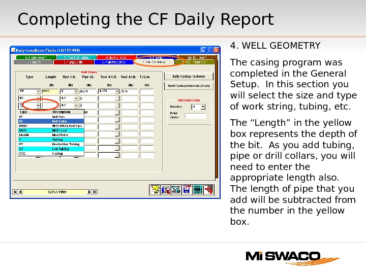
4. WELL GEOMETRY The casing program was completed in the General Setup. In this section you will select the size and type of work string, tubing, etc. The “Length” in the yellow box represents the depth of the bit. As you add tubing, pipe or drill collars, you will need to enter the appropriate length also. The length of pipe that you add will be subtracted from the number in the yellow box. Completing the CF Daily Report
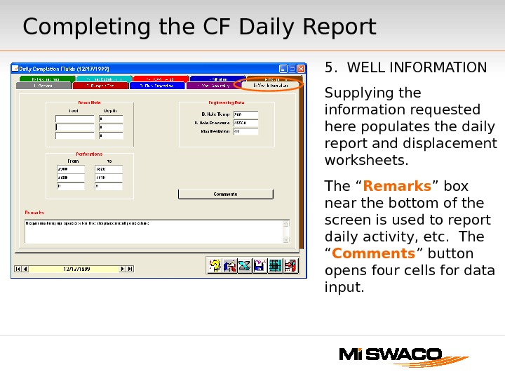
5. WELL INFORMATION Supplying the information requested here populates the daily report and displacement worksheets. The “ Remarks ” box near the bottom of the screen is used to report daily activity, etc. The “ Comments ” button opens four cells for data input. Completing the CF Daily Report
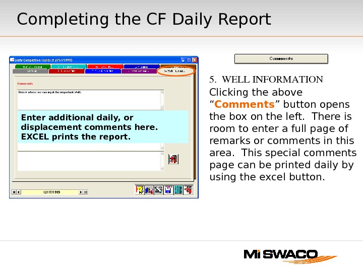
5. WELLINFORMATION Clicking the above “ Comments ” button opens the box on the left. There is room to enter a full page of remarks or comments in this area. This special comments page can be printed daily by using the excel button. Enter additional daily, or displacement comments here. EXCEL prints the report. Completing the CF Daily Report
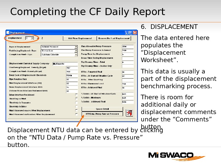
6. DISPLACEMENT The data entered here populates the “Displacement Worksheet”. This data is usually a part of the displacement benchmarking process. There is room for additional daily or displacement comments under the “Comments” button. Completing the CF Daily Report Displacement NTU data can be entered by clicking on the “NTU Data / Pump Rate vs. Pressure” button.
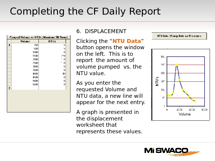
6. DISPLACEMENT Clicking the “ NTU Data ” button opens the window on the left. This is to report the amount of volume pumped vs. the NTU value. As you enter the requested Volume and NTU data, a new line will appear for the next entry. A graph is presented in the displacement worksheet that represents these values. Completing the CF Daily Report
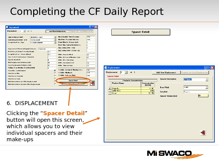
Completing the CF Daily Report 6. DISPLACEMENT Clicking the “ Spacer Detail ” button will open this screen, which allows you to view individual spacers and their make-ups
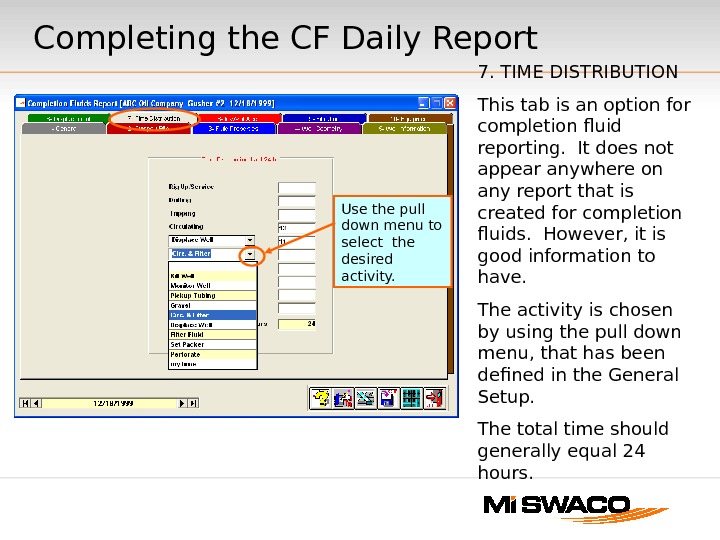
7. TIME DISTRIBUTION This tab is an option for completion fluid reporting. It does not appear anywhere on any report that is created for completion fluids. However, it is good information to have. The activity is chosen by using the pull down menu, that has been defined in the General Setup. The total time should generally equal 24 hours. Completing the CF Daily Report Use the pull down menu to select the desired activity.
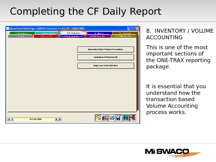
8. INVENTORY / VOLUME ACCOUNTING This is one of the most important sections of the ONE-TRAX reporting package. It is essential that you understand how the transaction based Volume Accounting process works. Completing the CF Daily Report
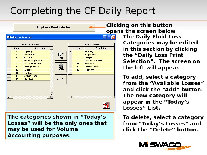
The Daily Fluid Loss Categories may be edited in this section by clicking the “Daily Loss Print Selection”. The screen on the left will appear. To add, select a category from the “Available Losses” and click the “Add” button. The new category will appear in the “Today’s Losses” List. To delete, select a category from “Today’s Losses” and click the “Delete” button. The categories shown in “Today’s Losses” will be the only ones that may be used for Volume Accounting purposes. Clicking on this button opens the screen below. Completing the CF Daily Report
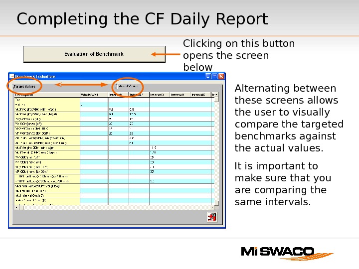
Clicking on this button opens the screen below Alternating between these screens allows the user to visually compare the targeted benchmarks against the actual values. It is important to make sure that you are comparing the same intervals. Completing the CF Daily Report
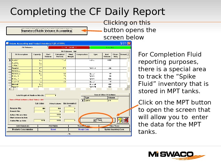
Clicking on this button opens the screen below For Completion Fluid reporting purposes, there is a special area to track the “Spike Fluid” inventory that is stored in MPT tanks. Click on the MPT button to open the screen that will allow you to enter the data for the MPT tanks. Completing the CF Daily Report
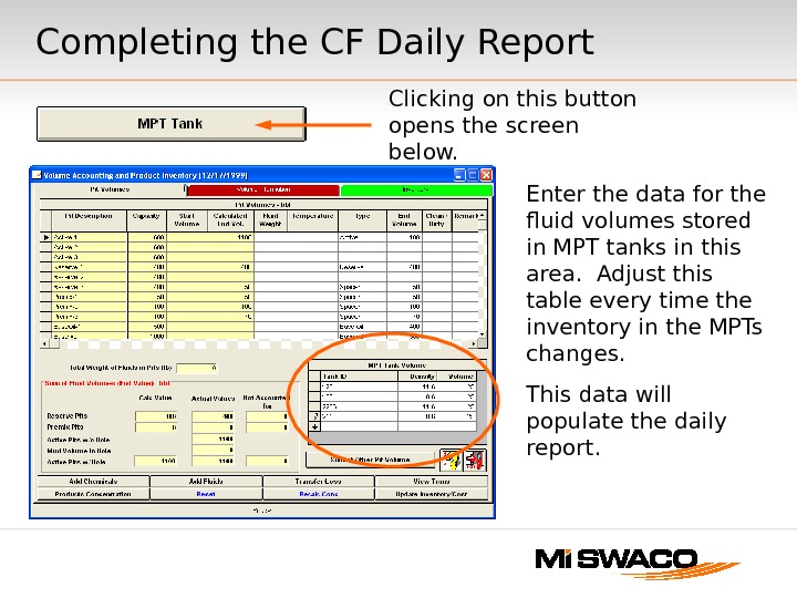
Clicking on this button opens the screen below. Enter the data for the fluid volumes stored in MPT tanks in this area. Adjust this table every time the inventory in the MPTs changes. This data will populate the daily report. Completing the CF Daily Report
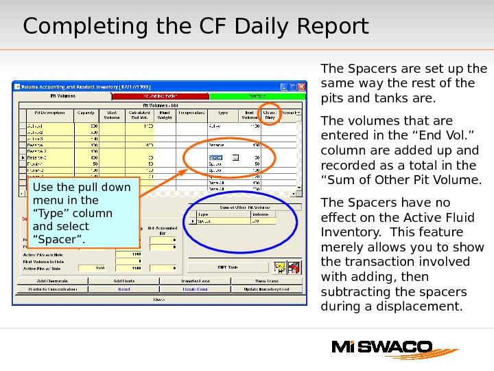
The Spacers are set up the same way the rest of the pits and tanks are. The volumes that are entered in the “End Vol. ” column are added up and recorded as a total in the “Sum of Other Pit Volume. The Spacers have no effect on the Active Fluid Inventory. This feature merely allows you to show the transaction involved with adding, then subtracting the spacers during a displacement. Completing the CF Daily Report Use the pull down menu in the “Type” column and select “Spacer”.
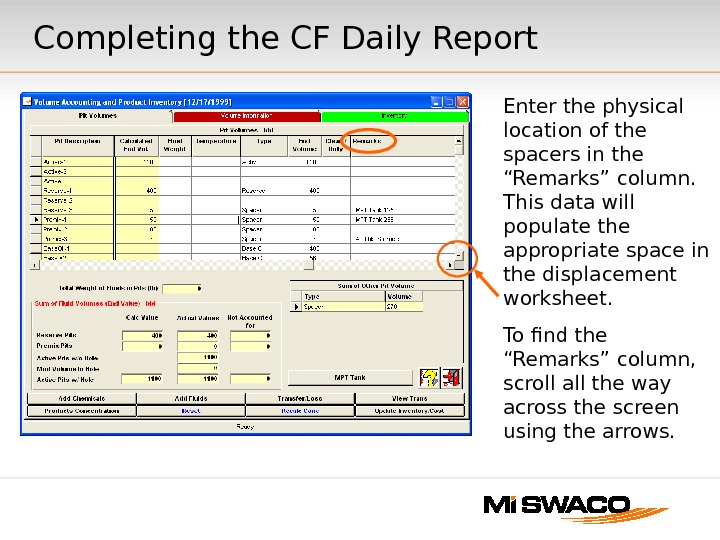
Enter the physical location of the spacers in the “Remarks” column. This data will populate the appropriate space in the displacement worksheet. To find the “Remarks” column, scroll all the way across the screen using the arrows. Completing the CF Daily Report
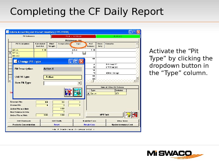
Activate the “Pit Type” by clicking the dropdown button in the “Type” column. Completing the CF Daily Report
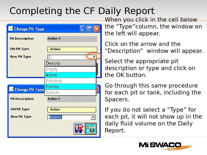
When you click in the cell below the “Type”column, the window on the left will appear. Click on the arrow and the “Description” window will appear. Select the appropriate pit description or type and click on the OK button. Go through this same procedure for each pit or tank, including the Spacers. If you do not select a “Type” for each pit, it will not show up in the daily fluid volume on the Daily Report. Completing the CF Daily Report
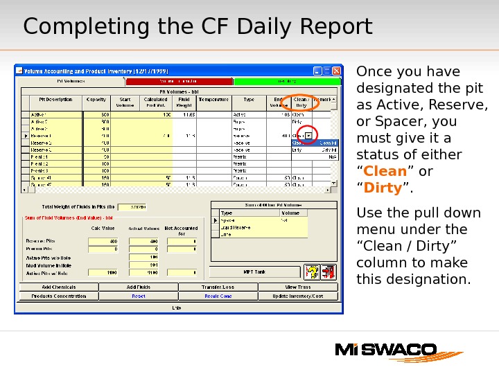
Once you have designated the pit as Active, Reserve, or Spacer, you must give it a status of either “ Clean ” or “ Dirty ”. Use the pull down menu under the “Clean / Dirty” column to make this designation. Completing the CF Daily Report
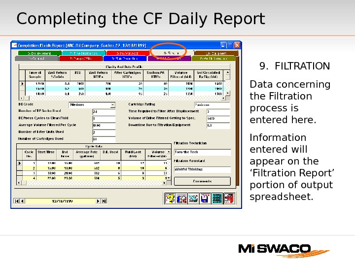
9. FILTRATION Data concerning the Filtration process is entered here. Information entered will appear on the ‘Filtration Report’ portion of output spreadsheet. Completing the CF Daily Report
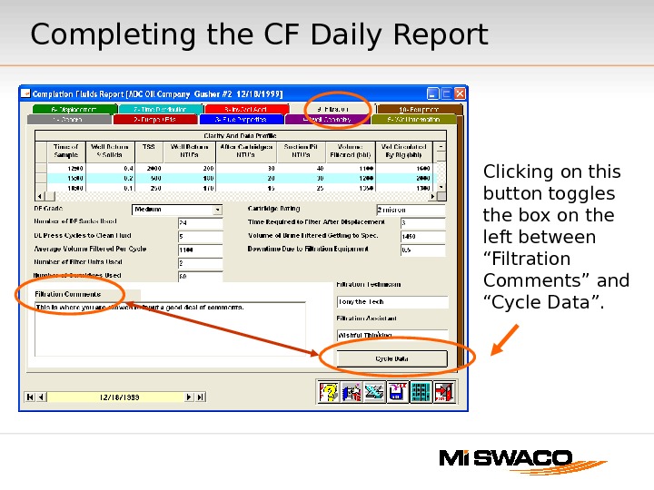
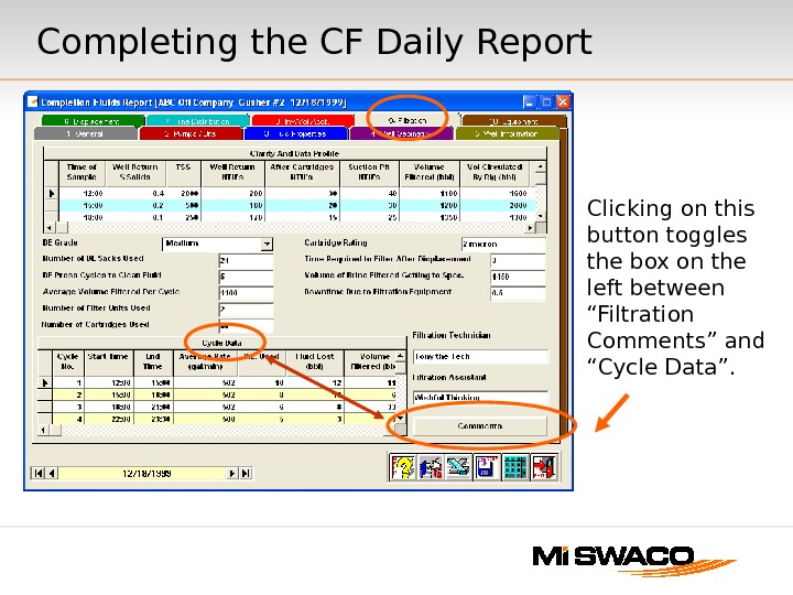
Clicking on this button toggles the box on the left between “Filtration Comments” and “Cycle Data”. Completing the CF Daily Report
Completing the CF Daily Report Clicking on this button toggles the box on the left between “Filtration Comments” and “Cycle Data”.
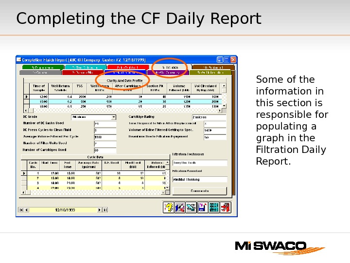
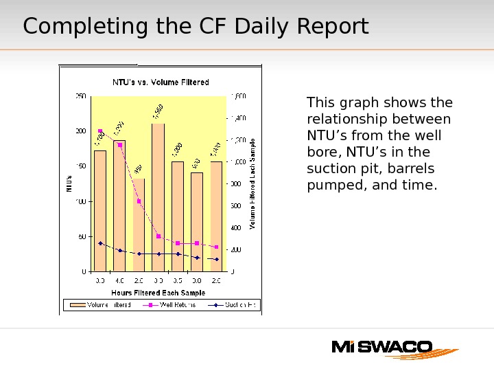
Some of the information in this section is responsible for populating a graph in the Filtration Daily Report. Completing the CF Daily Report
This graph shows the relationship between NTU’s from the well bore, NTU’s in the suction pit, barrels pumped, and time. Completing the CF Daily Report
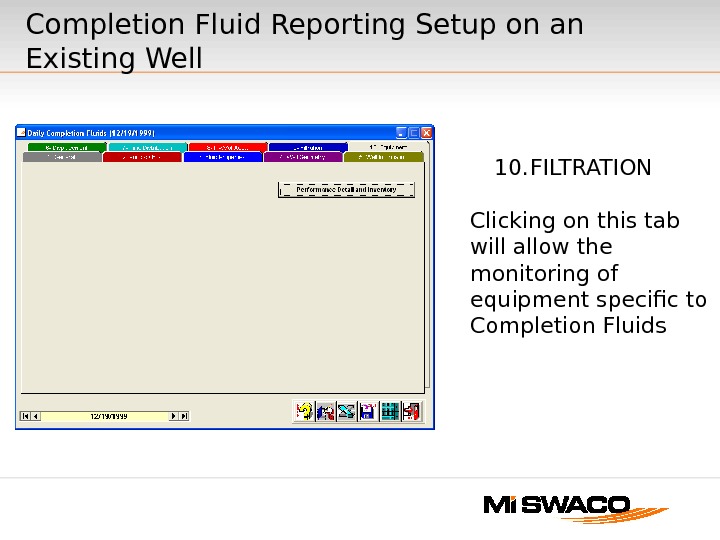
Completion Fluid Reporting Setup on an Existing Well 10. FILTRATION Clicking on this tab will allow the monitoring of equipment specific to Completion Fluids
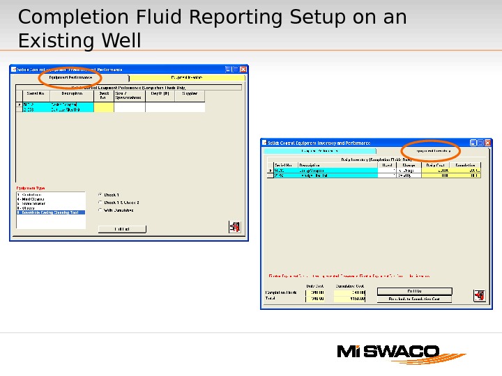
Completion Fluid Reporting Setup on an Existing Well
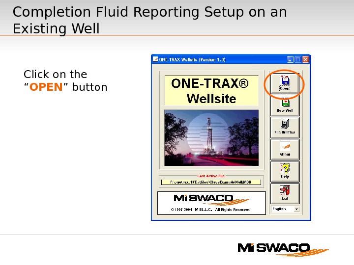
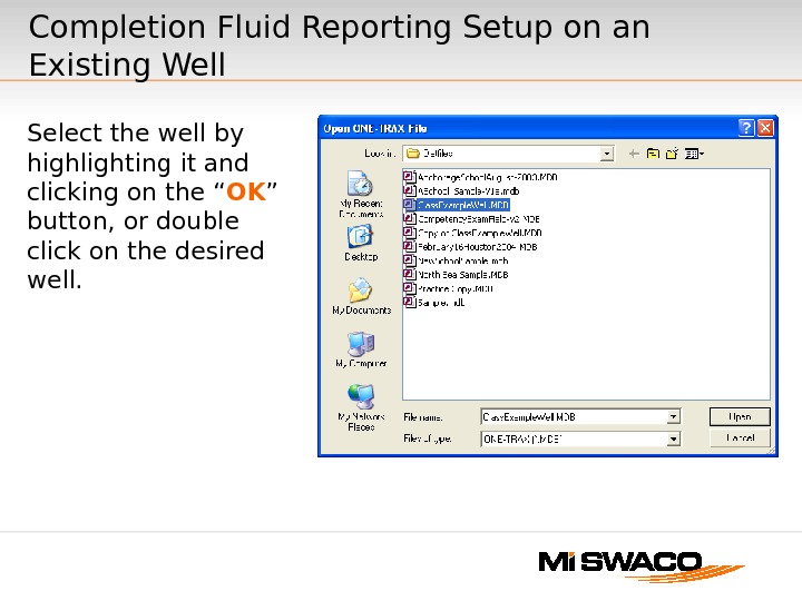
Completion Fluid Reporting Setup on an Existing Well Click on the “ OPEN ” button
Select the well by highlighting it and clicking on the “ OK ” button, or double click on the desired well. Completion Fluid Reporting Setup on an Existing Well
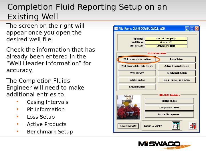
The screen on the right will appear once you open the desired well file. Check the information that has already been entered in the “Well Header Information” for accuracy. The Completion Fluids Engineer will need to make additional entries to: Casing Intervals Pit Information Loss Setup Active Products Benchmark Setup Completion Fluid Reporting Setup on an Existing Well
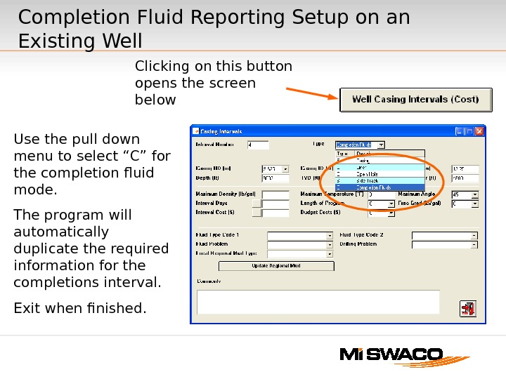
Clicking on this button opens the screen below. Completion Fluid Reporting Setup on an Existing Well Use the pull down menu to select “C” for the completion fluid mode. The program will automatically duplicate the required information for the completions interval. Exit when finished.
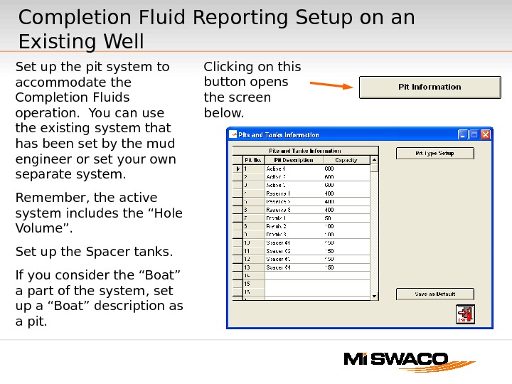
Clicking on this button opens the screen below. Set up the pit system to accommodate the Completion Fluids operation. You can use the existing system that has been set by the mud engineer or set your own separate system. Remember, the active system includes the “Hole Volume”. Set up the Spacer tanks. If you consider the “Boat” a part of the system, set up a “Boat” description as a pit. Completion Fluid Reporting Setup on an Existing Well
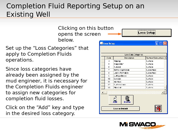
Clicking on this button opens the screen below. Set up the “Loss Categories” that apply to Completion Fluids operations. Since loss categories have already been assigned by the mud engineer, it is necessary for the Completion Fluids engineer to assign new categories for completion fluid losses. Click on the “Add” key and type in the desired loss category. Completion Fluid Reporting Setup on an Existing Well
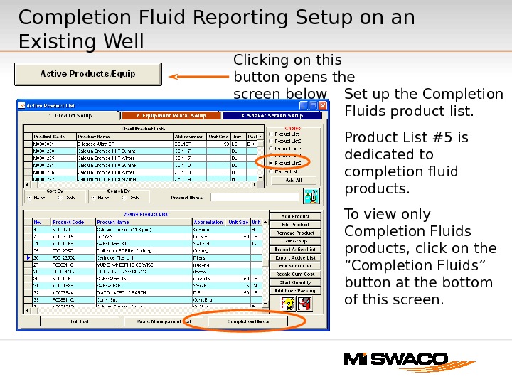
Clicking on this button opens the screen below Set up the Completion Fluids product list. Product List #5 is dedicated to completion fluid products. To view only Completion Fluids products, click on the “Completion Fluids” button at the bottom of this screen. Completion Fluid Reporting Setup on an Existing Well
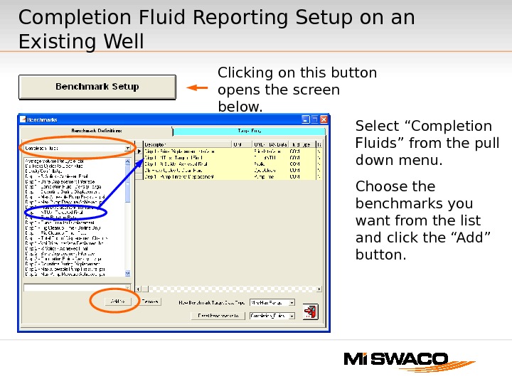
Clicking on this button opens the screen below. Select “Completion Fluids” from the pull down menu. Choose the benchmarks you want from the list and click the “Add” button. Completion Fluid Reporting Setup on an Existing Well
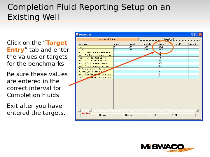
Click on the “ Target Entry ” tab and enter the values or targets for the benchmarks. Be sure these values are entered in the correct interval for Completion Fluids. Exit after you have entered the targets. Completion Fluid Reporting Setup on an Existing Well
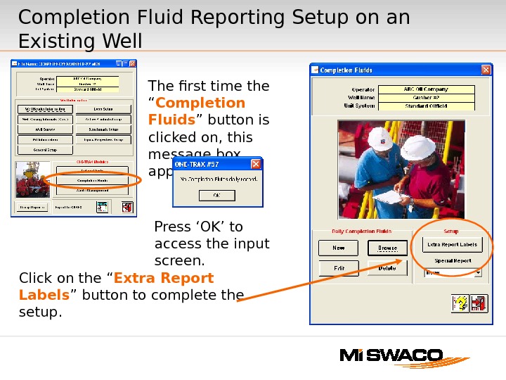
Completion Fluid Reporting Setup on an Existing Well The first time the “ Completion Fluids ” button is clicked on, this message box appears. Click on the “ Extra Report Labels ” button to complete the setup. Press ‘OK’ to access the input screen.
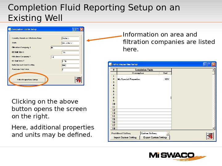
Clicking on the above button opens the screen on the right. Here, additional properties and units may be defined. Completion Fluid Reporting Setup on an Existing Well Information on area and filtration companies are listed here.
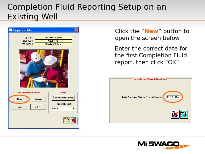
Click the “ New ” button to open the screen below. Enter the correct date for the first Completion Fluid report, then click “OK”. Completion Fluid Reporting Setup on an Existing Well
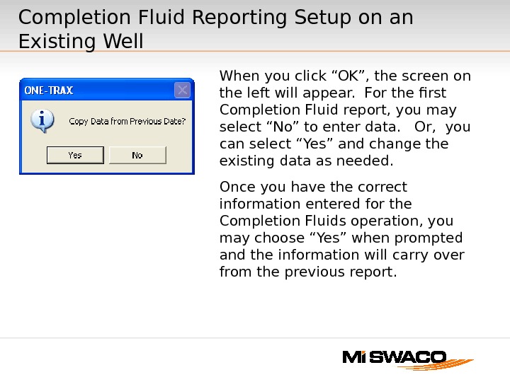
When you click “OK”, the screen on the left will appear. For the first Completion Fluid report, you may select “No” to enter data. Or, you can select “Yes” and change the existing data as needed. Once you have the correct information entered for the Completion Fluids operation, you may choose “Yes” when prompted and the information will carry over from the previous report. Completion Fluid Reporting Setup on an Existing Well
Provide the information for the ten tabs as required. Completion Fluid Reporting Setup on an Existing Well
QUESTIONS? ?
ONE-TRAX ® ® v 1. 3 Waste Management Module
Waste Management • New Product Service Line. • No Standard Reports. — Regional Reports. — Project Reports. — Non Existent Report. • Provides customer and M-I valuable project information.
Waste Management Module • Not a default option for ONE-TRAX. • Selected in General Setup.
Click Here To Select Waste Management Option Waste Management Module (Continued)
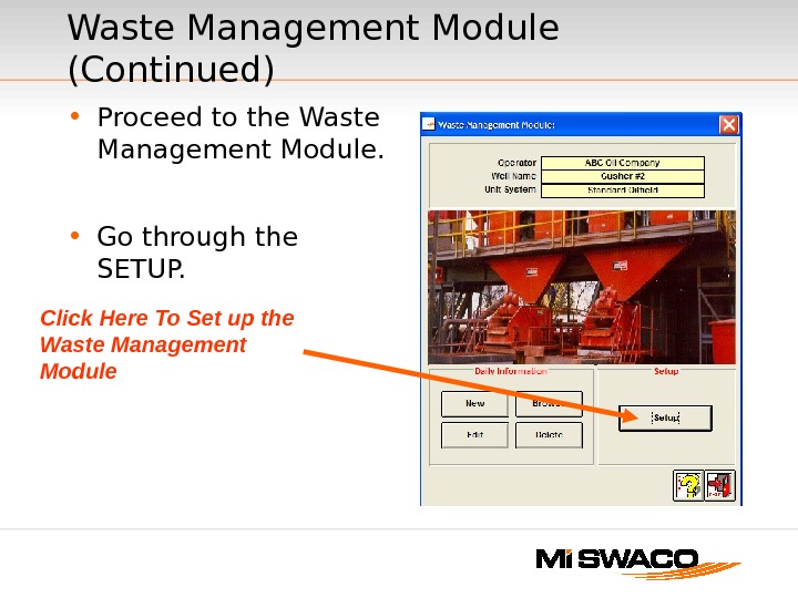
• Proceed to the Waste Management Module. • Go through the SETUP. Waste Management Module (Continued) Click Here To Set up the Waste Management Module
• Plan the Waste Management Setup carefully to avoid GIGO. ( G arbage In — G arbage Out)Waste Management Module (Continued)
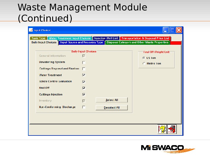
Waste Management Module (Continued)
Waste Management Options • Dewatering System. • Cuttings Disposal and Fixation. • Water Treatment. • Solids Control Evaluation. • Haul Off. • Cuttings Injection. • Non Conforming Discharge.
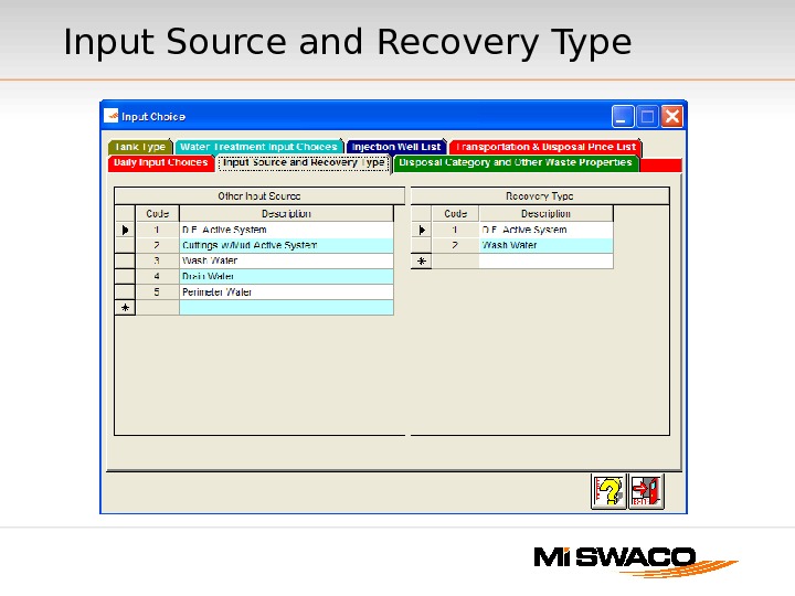
Input Source and Recovery Type • Input Source identifies all of the sources of waste that will have to be treated on location. — Drilling Fluid with Cuttings. — Oil Waste. — Wash Water. — Camp Waste etc. • Be as specific as possible when you start out. — You can always add a source later in the well. — You cannot delete a source once you have used that source without going back and changing every day that used that source.
Input Source and Recovery Type
Recovery Type • Designate where you may recycle the fluid or materials that are recovered from the waste streams. • Active Drilling Fluid. • Premix — Drilling Fluid or Dewatering. • Wash Water. • Injection Water.
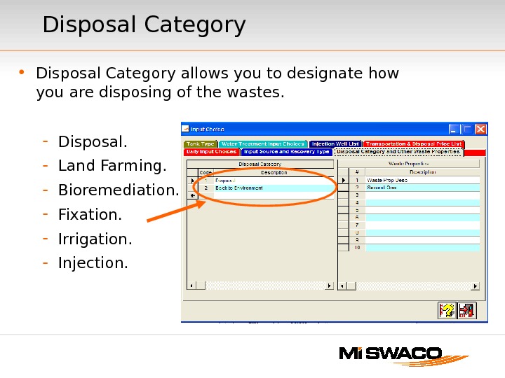
• Disposal Category allows you to designate how you are disposing of the wastes. — Disposal. — Land Farming. — Bioremediation. — Fixation. — Irrigation. — Injection. Disposal Category
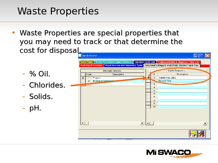
Waste Properties • Waste Properties are special properties that you may need to track or that determine the cost for disposal. — % Oil. — Chlorides. — Solids. — p. H.
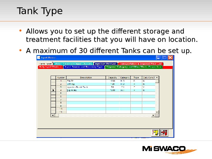
Tank Type • Allows you to set up the different storage and treatment facilities that you will have on location. • A maximum of 30 different Tanks can be set up.
• Capacity. • Category — Designates the type of waste and the treatment of the waste. — Dewatering. — Water Treatment. — Solids Processing/Fixation. — Cuttings Injection. — Haul Off. Tank Type ( Continued )
• Tank Use: — Storage — Processing • Bioremediation • Water Treatment • Dewatering • Injection • Concentration: — Calculated chemical concentration of waste treatment. Tank Type ( Continued )
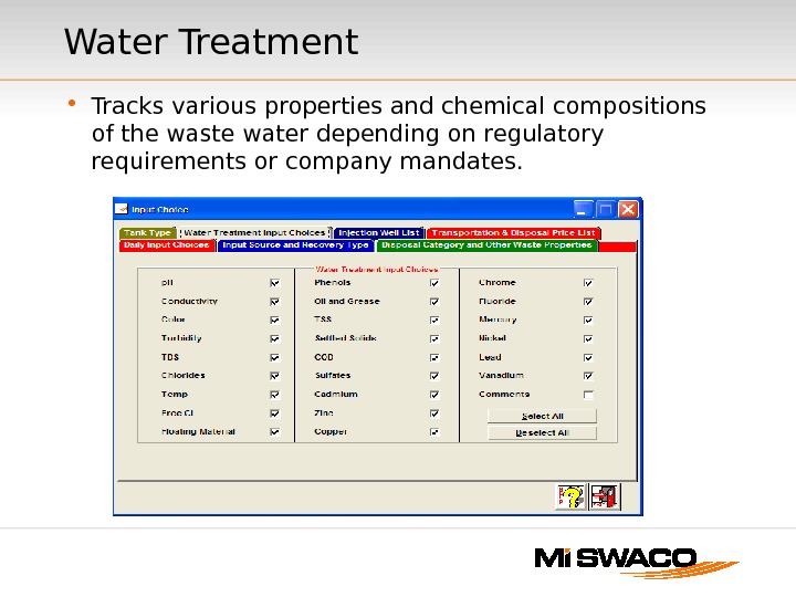
Water Treatment • Tracks various properties and chemical compositions of the waste water depending on regulatory requirements or company mandates.
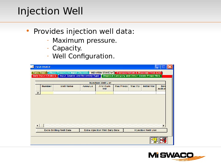
Injection Well • Provides injection well data: — Maximum pressure. — Capacity. — Well Configuration.
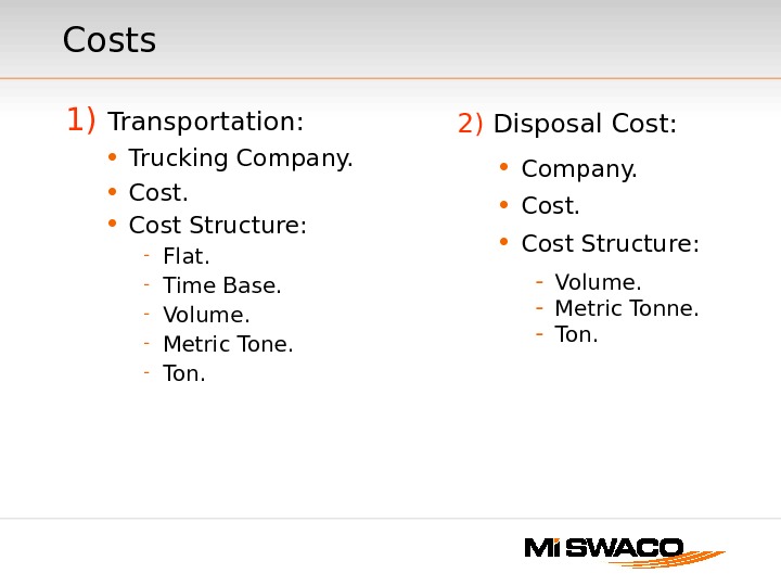
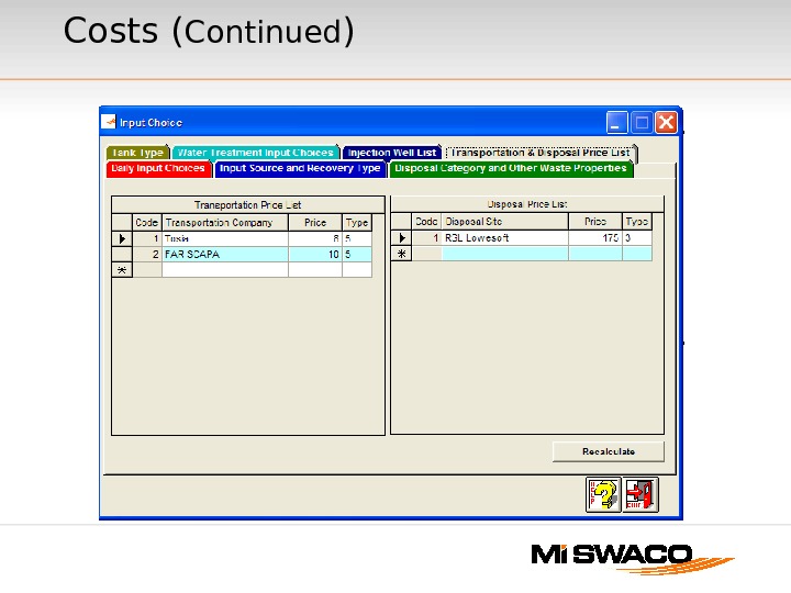
Costs 1) Transportation: • Trucking Company. • Cost Structure: — Flat. — Time Base. — Volume. — Metric Tone. — Ton. 2) Disposal Cost: • Company. • Cost Structure: — Volume. — Metric Tonne. — Ton.
Costs ( Continued )
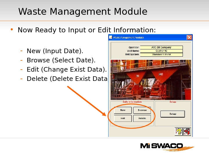
• Now Ready to Input or Edit Information: — New (Input Date). — Browse (Select Date). — Edit (Change Exist Data). — Delete (Delete Exist Data). Waste Management Module
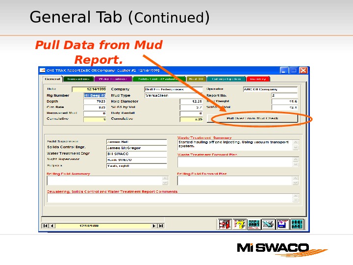
General Tab • Pull Data from Mud Report — Depth. — Solids. — Mud Weight. — Flow Rate. — Hole Size. • Insert Comment for Mud, Solids Control or Waste Treatment. • Waste Management Personnel.
General Tab ( Continued ) Pull Data from Mud Report.
Transactions • This tab handles over 75% of all of the data for the Waste Management Module. • Input the Source of Waste. • Designate where the waste is handled. • Provide Waste Information Volume, Density and Weight. Note : — Program only uses two to calculate third. — Once a density is in the field, it will automatically update weight or volume if one changes. • Other Waste Information — Time, p. H and Solids.
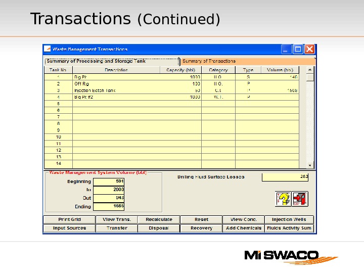
Transactions (Continued)
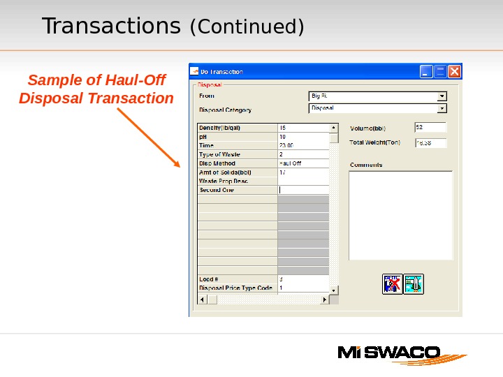
Sample of Haul-Off Disposal Transactions (Continued)
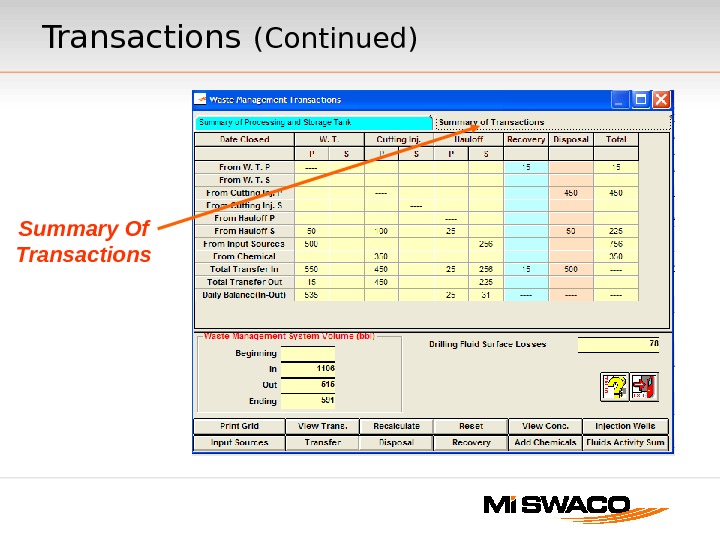
Summary Of Transactions (Continued)
Transactions (Continued) • Waste Movements: — Transfer (Transfers waste to the various waste treatment processes). — Disposal (Disposes of waste through the designated disposal method). • Input waste properties. • If this is a Haul-Off Tank, Trucking and Disposal options will be asked. — Recovery (Designate Source and Destination).
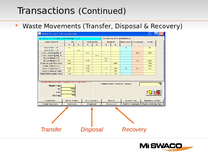
• Waste Movements (Transfer, Disposal & Recovery)Transactions (Continued) Transfer Disposal Recovery
Add Chemicals • If any chemicals are used to treat water or chemicals they must be added to the appropriate pit prior to disposal or recovery in order to calculate the concentration of the chemical.
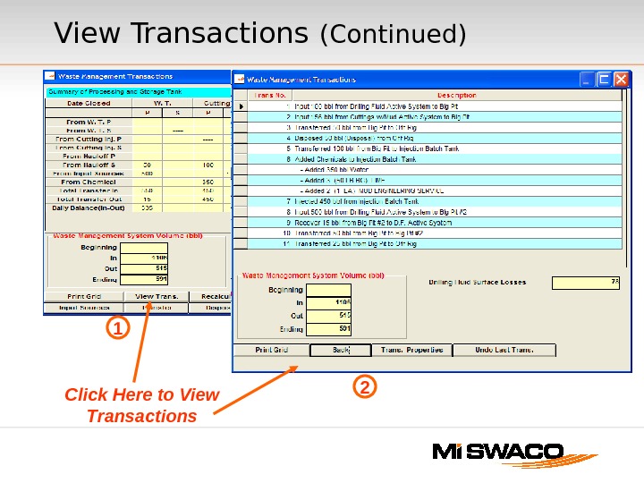
View Transactions • View Transactions — allows you to look at individual transactions. You can delete the last transaction. If an error occurs early in the transactions you must delete transactions one at a time until you delete the error. Then all of the transactions must be input again. • Reset — Deletes all Transactions and any Inputs for the day and restores to previous days data.
View Transactions (Continued) Click Here to View Transactions
Remaining Tabs • Fluids Activities — Fluid Movements. • Print Grid — Prints movements of fluids and wastes. • Recalculate — Costs and concentrations. • View Concentrations — Shows concentrations of dewatering, water treatment or cuttings treatment. • Injection wells — Injection well data.
Summary • Tanks: — Description • Capacity • Category • Type • Volume • Transactions: — Movements of Wastes
Individual Services • Dewatering: — Data is filled in from Transactions • Cutting Disposal and Fixation: — Some volume data is required to show water and oil base cuttings and sludge along with % oil and % water. • Water Treatment: — Designate up to five (5) sampling point and input the water properties designated in the setup. Pit volumes are automatically transferred from Transactions.
• Solids Control: — Evaluates the various pieces of equipment. Data can be input or will transfer from Drilling Fluids module. • Haul Off: — Provides a table of all the loads moved that day along with cost information. • Cuttings Injection: — Inputs are required for slurry properties along with unit running times and downtimes. Individual Services (Continued)
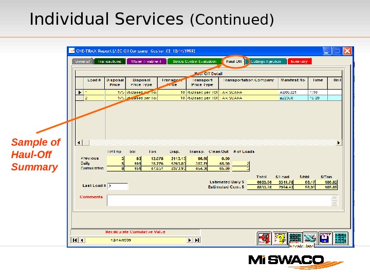
Sample of Haul-Off Summary Individual Services (Continued)
Inventory • Chemicals. — Waste Management Personnel — Waste Management Chemicals — All Products • Dewatering Chemicals • Solids Control Equipment • Other Equipment • Shaker Screens
Inventory ( Continued )
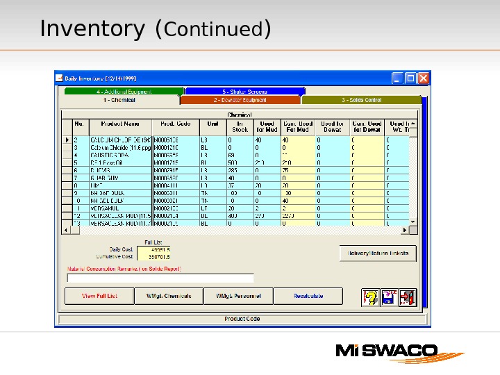
• Note: Some of this data will transfer from the Drilling Fluid Module if it was input and pulled over. If not you will have to input the data here. • Calculates costs for Waste Management equipment and personnel. Be careful not to duplicate materials received or materials used from drilling fluid inputs. Inventory ( Continued )
Reporting • All of the reports are done in Excel. • Access reports in the Drilling Fluid Module or the Waste Management Module. • Press the Excel Icon on the page. • Select IFE Report. • Select desired reports.
Reports • Developed based on reports used throughout the world. • Developed to meet special customer needs. • Additional reports can be developed based on customer and project needs.
Waste Management Reporting • Standard program is new to Mi. SWACO • Designed to capture the data from all of the Waste Management product service lines • Flexible reporting available with Excel • Recapping now available for submission to customer