c0d2e72d8a2171ff8e9df64bcf723f86.ppt
- Количество слайдов: 32


On the Way to ILC Shekhar Mishra Fermilab Talk presented on behalf of ILC-GDE 2/16/06 Talk Presented at the 2006 Aspen Winter Conference: "Particle Physics at the Verge of Discovery"
 – Initial maximum energy of 500 Ge.")
International Linear Collider: Performance Specification (White Paper) – Initial maximum energy of 500 Ge. V, operable over the range 200 -500 Ge. V for physics running. – Equivalent (scaled by 500 Ge. V/ s) integrated luminosity for the first four years after commissioning of 500 fb-1. – Ability to perform energy scans with minimal changeover times. – Beam energy stability and precision of 0. 1%. – Capability of 80% electron beam polarization over the range 200 -500 Ge. V. – Two interaction regions, at least one of which allows for a crossing angle enabling gg collisions. – Ability to operate at 90 Ge. V for calibration running. – Machine upgradeable to approximately 1 Te. V.
 : Superconducting RF is accelerating")
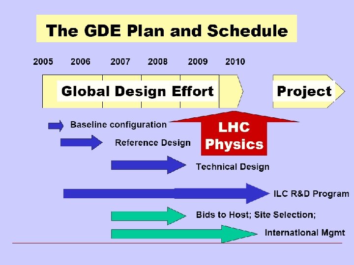
Road to: Reference Design Report ITRP Recommendation (Aug 2004) : Superconducting RF is accelerating technology for ILC • 1 st ILC Workshop at KEK (11/2004) – working groups (WG) formed to begin identifying contentious design issues • 2 nd ILC Workshop Snowmass (8/2005) – modified WG continue identifying baseline design and alternatives – newly formed ‘Global Groups’ begin to discuss and catalogue global design issues – 2 nd Snowmass week: concentrate on the list of ‘Top 40’ critical design questions • 1 st Meeting of the ILC-GDE (12/2005) – – Acceptance of the Baseline Configuration Document (BCD) Start work towards the Reference Design Report (12/2006, with Cost) Formation of Accelerator System, Technology and Global systems Formation of • Design and Cost Board, Change Control Board and R&D Board

GDE RDR / R&D Organization FALC ICFA FALC Resource Board ILCSC GDE Directorate GDE Executive Committee GDE R & D Board GDE Change Control Board Global R&D Program GDE Design Cost Board RDR Design Matrix

GDE RDR / R&D Organization FALC ICFA FALC Resource Board ILCSC GDE Directorate GDE Executive Committee GDE R & D Board ILC R&D Program GDE Change Control Board Global R&D Program GDE Design Cost Board RDR Design Matrix ILC Design Effort

Mission of Global Design Effort • Produce a design for the ILC that includes – – – A detailed design concept Performance assessments Reliable international costing An industrialization plan Siting analysis Detector concepts and scope • Coordinate worldwide prioritized proposal driven R & D efforts – To demonstrate and improve the performance – Reduce the costs – Attain the required reliability, etc.
 ~30 km RTML ~1. 6 km 20 mr")
The Baseline Machine (500 Ge. V) ~30 km RTML ~1. 6 km 20 mr 2 mr ML ~10 km (G = 31. 5 MV/m) BDS 5 km e+ undulator @ 150 Ge. V (~1. 2 km) R = 955 m E = 5 Ge. V not to scale x 2

Luminosity Table Bunch charge Number of bunches Linac bunch interval Bunch length Vertical emittance IP beta (500 Ge. V) IP beta (1 Te. V) N nb tb sz gey bx by min 1 1330 154 150 0. 03 10 0. 2 nom 2 2820 308 300 0. 04 21 0. 4 30 0. 3 max 2 x 10^10 5640 461 ns 500 mm 0. 08 mm. mrad 21 mm 0. 4 mm 30 mm 0. 6 mm

Baseline Electron Source • DC Guns incorporating photocathode illuminated by a Ti: Sapphire drive laser. • Long electron microbunches (~2 ns) are bunched in a bunching section • Accelerated in a room temperature linac to about 100 Me. V and SRF linac to 5 Ge. V. laser E=70 -100 Me. V Positron-style roomstandard ILC temperature SCRF modules accelerating section sub-harmonic bunchers + solenoids diagnostics section

Baseline Positron Source • Helical Undulator Based Positron Source with Keep Alive System – The undulator source will be placed at the 150 Ge. V point in main electron linac. Primary esource • This will allow constant charge operation across the foreseen centre-of-mass energy operating range. Beam Delivery System e. DR 150 Ge. V 100 Ge. V Helical Undulator In By-Pass Line Auxiliary Source Photon Collimators Positron Linac IP 250 Ge. V e+ DR Target e. Dump Photon Beam Dump e- Photon Target Adiabatic Matching Device e+ preaccelerator ~5 Ge. V

ILC Damping Ring: Baseline Design • Positrons: Two rings of ~ 6 km circumference in a single tunnel. • Two rings are needed to reduce e-cloud effects unless significant progress can be made with mitigation techniques. • Preferred to 17 km due to: –Space-charge effects –Acceptance –Tunnel layout (commissioning time, stray fields) • Electrons: one 6 km ring. • Preferred to 3 km due to: –Larger gaps between mini-trains for clearing ions. –Injection and extraction kickers ‘low risk’

Main Linac: Baseline RF Unit

SRF Cavity Gradient Cavity type Qualified gradient Operational Length* energy gradient MV/m initial upgrade MV/m Km Ge. V TESLA 35 31. 5 10. 6 250 LL 40 36. 0 +9. 3 500 * assuming 75% fill factor Total length of one 500 Ge. V linac 20 km

Baseline ILC Cryomodule • The baseline ILC Cryomodule will have 8 9 -Cell cavities per cryomodule. The quadrupole will be at the center in the baseline design. • Every 4 th cryomodule in the linac would include a quadrupole with a corrector and BPM package.

Modulator Baseline Alternate Operation: an array of capacitors is charged in parallel, discharged in series. (~2 m) The Bouncer Compensated Pulse Transformer Style Modulator Will test full prototype in 2006

RF Power: Baseline Klystrons Specification: 10 MW MBK 1. 5 ms pulse 65% efficiency Thales CPI Toshiba ILC (XFEL @ DESY) has a very limited experience with these Klystrons. Production and operation of these Klystron are issues that needs to be addressed.

Beam Delivery System: Baseline & Alternatives • Baseline (supported, at the moment, by GDE exec) – two BDSs, 20/2 mrad, 2 detectors, 2 longitudinally separated IR halls • Alternative 1 – two BDSs, 20/2 mrad, 2 detectors in single IR hall @ Z=0 • Alternative 2 – single IR/BDS, collider hall long enough for two push-pull detectors

From Baseline to a RDR July Jan Frascati Bangalore Vancouver Dec 2006 Valencia Freeze Configuration Organize for RDR Review Design/Cost Methodology Review Initial Design / Cost Design and Costing Review Final Design / Cost RDR Document Release RDR

ILC R&D • Major laboratories around the world are working on the ILC Accelerator R&D. – Europe • • • DESY (TESLA) (55 Institutions) European XFEL CARE (11 Institutions) Euro. Te. V (27 Institutions) UK-LCABD (15 Institutions) – Americas (9 Laboratories and Universities) • Fermilab • SLAC – Asia (6 Institution in 5 countries) • KEK Some Highlights of R&D Activities

Key Issues: ILC Main Linac Accelerator Technology • The feasibility demonstration for the ILC requires that a cryomodule be assembled and tested at the design gradient of 35 MV/m. – Cavity technology development to routinely achieve > 35 MV/m and Q ~0. 51 e 10, • Finalize the design of an RF Unit and evaluate the reliability issues. It is important to fully test the basic building block of the Linac. • High Power Coupler, HOM, Tuner etc. • 10 MWatt Multi-Beam Klystron, Fabrication, Operation and reliability • RF Distribution, Controls and LLRF • Instrumentation and Feedback • Quadrupole, Corrector and Instrumentation package • Cryogenic Distribution

Europe: ILC R&D • DESY is leading the ILC R&D in Europe. The XFEL at DESY uses ILC Technology and have common R&D goals. – Cavity Gradient – Industrial studies and development of Main Linac Components. • • • Coupler RF Power Cryogenics (LHC) Instrumentation Beam Delivery System

DESY: ILC Accelerator Modules in Operation RF gun Diagnostics Bunch Laser Compressor 5 Me. V 127 Me. V Accelerating Structures Collimator Bunch Compressor 370 Me. V 445 Me. V Undulators bypass FEL diagnostics 250 m In single cavity measurements 6 out of 8 cavities reach 30 MV/m! At present DESY is operating modules 2* ACC 1 Febr 04 1* ACC 2 June 02 3* ACC 3 April 03 4 ACC 4 April 03 5 ACC 5 April 03 ACC 5

ILC R&D at Fermilab • ILC R&D effort at Fermilab is focused on key design & technical issues in support of the RDR, cost estimate and eventually the CDR for the ILC. • We also have the goal of positioning the Americas to host the ILC at Fermilab • Our efforts are focused on two main areas of the ILC – Main Linac Design – Civil and Site Development • Main Linac R&D: – The goals are to demonstrate the feasibility of all Main Linac technical components, develop engineering designs, estimate costs, explore cost reduction, and engage US industry • Civil and Site Development – Fermilab is working with the GDE and international partners to develop a matrix for comparing possible ILC sites – We also work to develop U. S. sites on or near Fermilab

ILC 1. 3 GHz Cavities @ FNAL Bead pull RF Testing @ FNAL Joint ANL/FNAL BCP/EP Facility 4 cavities received from ACCEL 4 cavities on order at AES 4 cavities expected from KEK • • Industrial fabrication of cavities. BCP and vertical testing at Cornell (25 MV/m) EP and vertical testing at TJNL. ( 35 MV/m) Joint BCP/EP facility being developed ANL (late 06) High Power Horizontal test facility @ FNAL (ILCTA-MDB) Vertical test facility under development @ FNAL ( IB 1) Single/large Crystal cavity development with TJNL

Jlab: Large Grain/Single Crystal Niobium Nb Discs LL cavity 2. 3 GHz Epeak/Eacc = 2. 072 Hpeak/Eacc = 3. 56 m. T/MV/m
 • Strong efforts throughout the design effort – Electron and")
SLAC: Accelerator Design (RDR) • Strong efforts throughout the design effort – Electron and positron sources – Contributions to the damping rings and RMTL – Main linac design and instrumentation – Rf sources – Beam Delivery System – Civil construction and conventional facilities • Able to provide leadership for some RDR Area Sub-systems
 – Linac rf sources")
SLAC: ILC R&D Program • Broad R&D Program (cont. ) – Linac rf sources • Marx generator modulator Positron capture structures 12 KV Marx Cell – Electron and Positron sources • NC structure, E-166, electron laser, and cathode SEY Test Chamber for PEP-II – Damping rings • SEY studies in PEP-II

KEK: ILC Activities Highlights

KEK ATF Facility for DR and FF

KEK: Main Linac RF Unit R&D Goal: Achieve Higher Gradient >40 MV/m in a new Cavity Design

Summary • After the technology selection the ILC Collaboration has made considerable progress towards the design of the ILC. • The Baseline and Alternate design for each major Accelerator subsystems were defined at Snowmass 2005. • The ILC-GDE has a approved the Baseline Configuration Document. • The ILC-GDE is developing the ILC Reference Design Report, with cost estimate. It is expected to be done by the end of CY 06 • The ILC R&D around the world is moving fast with focus on key Accelerator Issues.
c0d2e72d8a2171ff8e9df64bcf723f86.ppt