
Object-Oriented Programming and Java Part III: Object-Oriented


part_iii_object-oriented_analysis.ppt
- Размер: 1.6 Mегабайта
- Количество слайдов: 90
Описание презентации Object-Oriented Programming and Java Part III: Object-Oriented по слайдам
Object-Oriented Programming and Java Part III: Object-Oriented Analysis with UML Course by Mr. Erkki Mattila, M. . Sc. . Rovaniemi University of Applied Sciences
OOP — Rovaniemi University of Applied Sciences. Course Contents Part I: Object-Oriented Concepts and Principles Part II: Object-oriented Programming Closer look at the concepts of OOP Part III: Object-oriented Analysis and Design Using Unified Modeling Language (UML) in OOA and OO
OOP — Rovaniemi University of Applied Sciences. Unified Modelling Language Several different notations for describing object-oriented designs were proposed in the 1980 s and 1990 s. The Unified Modelling Language is an integration of these notations. It describes notations for a number of different models that may be produced during OO analysis and design. It is now a de facto standard for OO modelling.
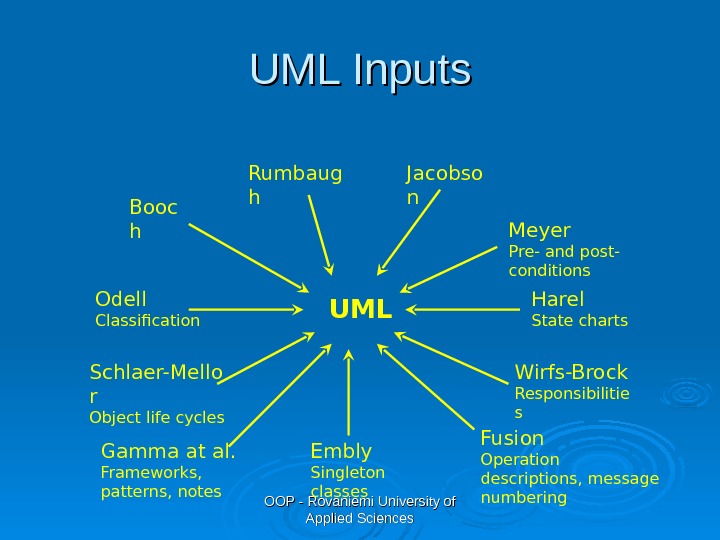
OOP — Rovaniemi University of Applied Sciences. UML Inputs Meyer Pre- and post- conditions UMLRumbaug h Jacobso n Booc h Odell Classification Schlaer-Mello r Object life cycles Gamma at al. Frameworks, patterns, notes Embly Singleton classes Wirfs-Brock Responsibilitie s Fusion Operation descriptions, message numbering Harel State charts
OOP — Rovaniemi University of Applied Sciences. Evolution of the UML The first public draft (version 0. 8) in Oct ober 1995. Versions 0. 9 and 0. 91 in 1996 included Ivar Jacobson’s input. Version 1. 0 was presented for standardization in July 1997. Additional enhancements were incorporated into the 1. 1 version, presented in Sep tember 1997. In Nov ember 1997, the UML was adopted as the standard modeling language by the Object Management Group (OMG) The current version is 2. 0, the previous release was 1.
OOP — Rovaniemi University of Applied Sciences. Object-Oriented Analysis The intent of OOA is to define all classes that are relevant to the problem, and the relationships and behaviour associated with them OOA provides you with a concrete way to represent your understanding of requirements and then test that understanding against the customer’s perception of the system to be built
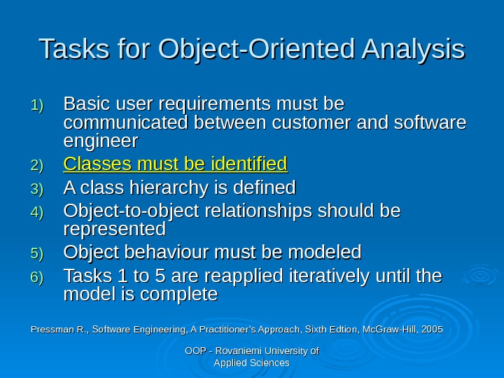
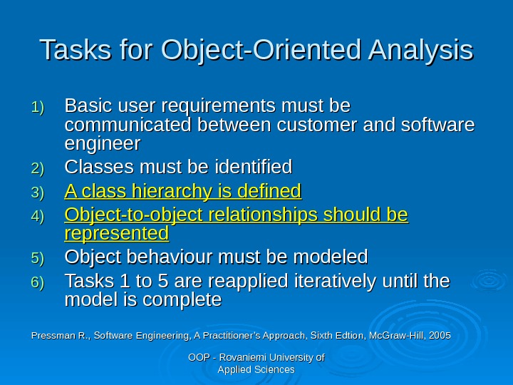
OOP — Rovaniemi University of Applied Sciences. Tasks for Object-Oriented Analysis 1)1) Basic user requirements must be communicated between customer and software engineer 2)2) Classes must be identified 3)3) A class hierarchy is defined 4)4) Object-to-object relationships should be represented 5)5) Object behaviour must be modeled 6)6) Tasks 1 to 5 are reapplied iteratively until the model is complete Pressman R. , Software Engineering, A Practitioner’s Approach, Sixth Edtion, Mc. Graw-Hill,
OOP — Rovaniemi University of Applied Sciences. What Is a Use Case? Formal description: Use case is a series of steps an actor performs on a system to achieve a goal. Informal description: A Use case is a description of one small task the user would do when using the system. Something that the user wants to accomplish, e. g. I would like to borrow a book. Each use case constitutes a complete course of action initiated by an actor, and it specifies the interaction that takes place between an actor and the system.
OOP — Rovaniemi University of Applied Sciences. What Is an Actor? Informal description: actors are types of users. Different types of people or devices that use the system or product. Often relates to the roles people have in a company For example, in a library system one actor could be a customer and another a librarian. Formal description: an actor is anything that communicates with the system or product that is external to the system itself.
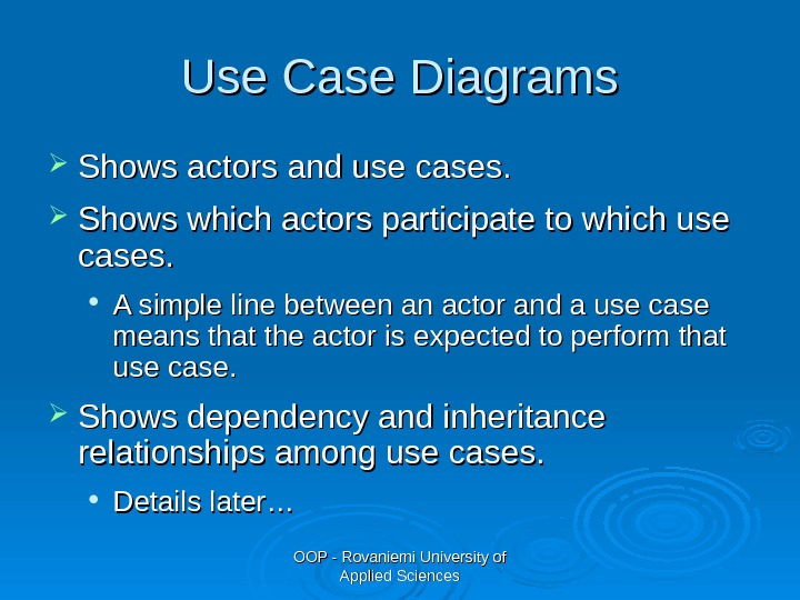
OOP — Rovaniemi University of Applied Sciences. Use C C ase Diagrams Shows actors and use cases. Shows which actors participate to which use cases. A simple line between an actor and a use case means that the actor is expected to perform that use case. Shows dependency and inheritance relationships among use cases. Details later…
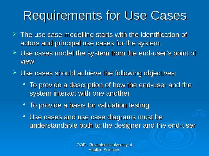
OOP — Rovaniemi University of Applied Sciences. Requirements for Use Cases The use case modelling starts with the identification of actors and principal use cases for the system. Use cases model the system from the end-user’s point of view Use cases should achieve the following objectives: To provide a description of how the end-user and the system interact with one another To provide a basis for validation testing Use cases and use case diagrams must be understandable both to the designer and the end-user
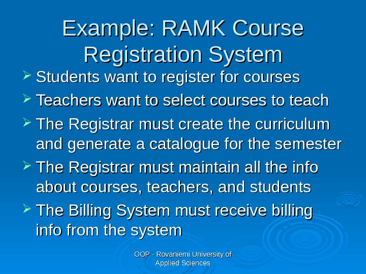
OOP — Rovaniemi University of Applied Sciences. Example: RAMK Course Registration System Students want to register for courses Teachers want to select courses to teach The Registrar must create the curriculum and generate a catalogue for the semester The Registrar must maintain all the info about courses, teachers, and students The Billing System must receive billing info from the system
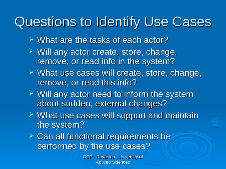
OOP — Rovaniemi University of Applied Sciences. Questions to Identify Use Cases What are the tasks of each actor? Will any actor create, store, change, remove, or read info in the system? What use cases will create, store, change, remove, or read this info? Will any actor need to inform the system about sudden, external changes? What use cases will support and maintain the system? Can all functional requirements be performed by the use cases?
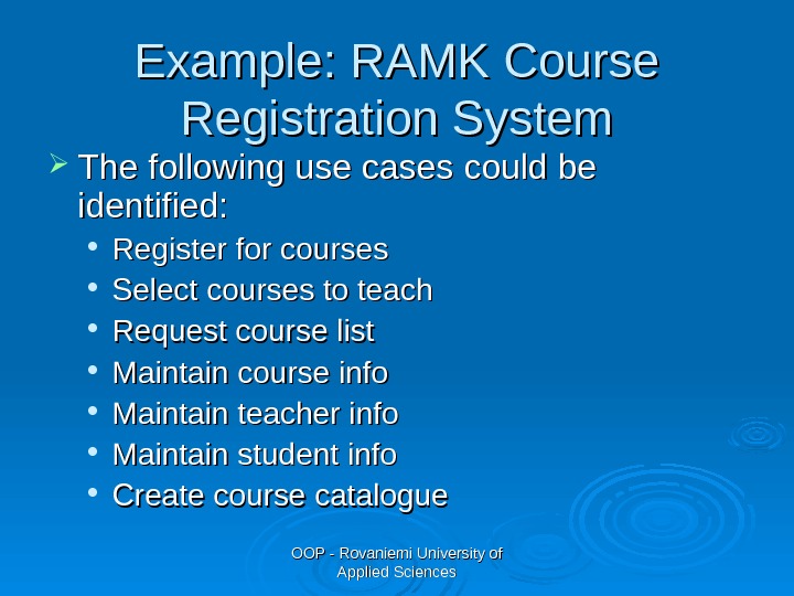
OOP — Rovaniemi University of Applied Sciences. Example: RAMK Course Registration System The following use cases could be identified: Register for courses Select courses to teach Request course list Maintain course info Maintain teacher info Maintain student info Create course catalogue
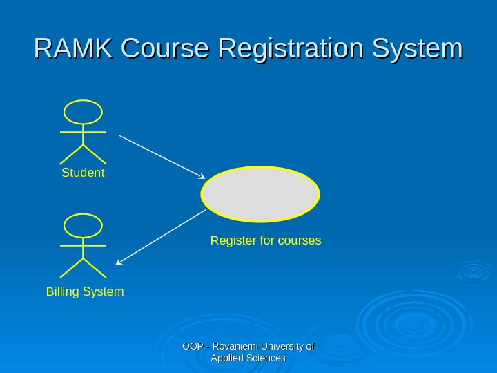
OOP — Rovaniemi University of Applied Sciences. RAMK Course Registration System Student Billing System Register for courses
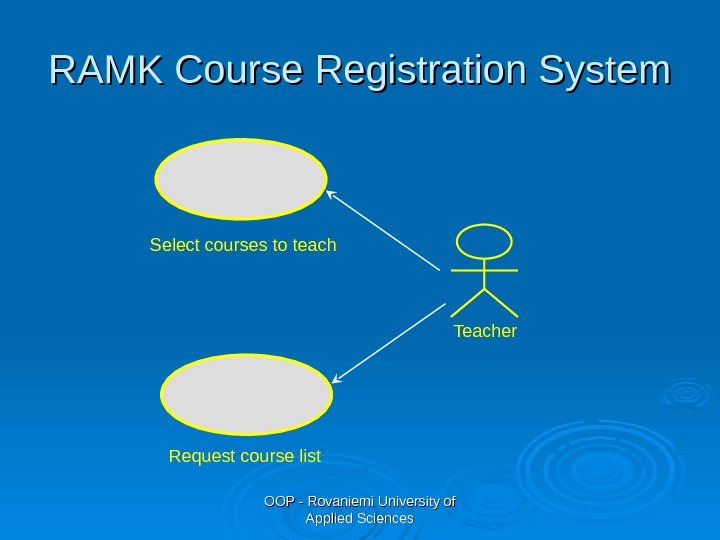
OOP — Rovaniemi University of Applied Sciences. RAMK Course Registration System Teacher. Select courses to teach Request course list
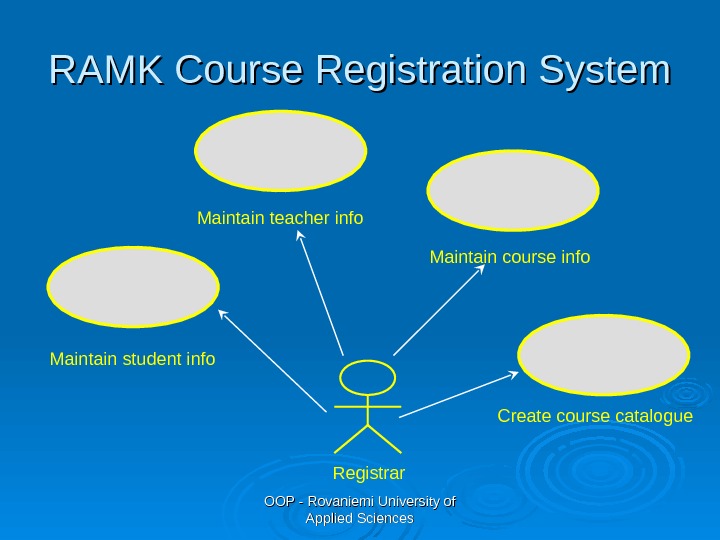
OOP — Rovaniemi University of Applied Sciences. RAMK Course Registration System Registrar. Maintain student info Maintain teacher info Maintain course info Create course catalogue
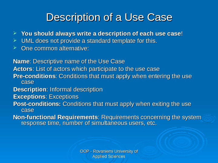
OOP — Rovaniemi University of Applied Sciences. Description of a Use Case You should always write a description of each use case !! UML does not provide a standard template for this. One common alternative: Name : Descriptive name of the Use Case Actors : List of actors which participate to the use case Pre-conditions : Conditions that must apply when entering the use case Description : Informal description Exceptions : Exceptions Post-conditions: Conditions that must apply when exiting the use case Non-functional Requirements : Requirements concerning the system response time, number of simultaneous users, etc.
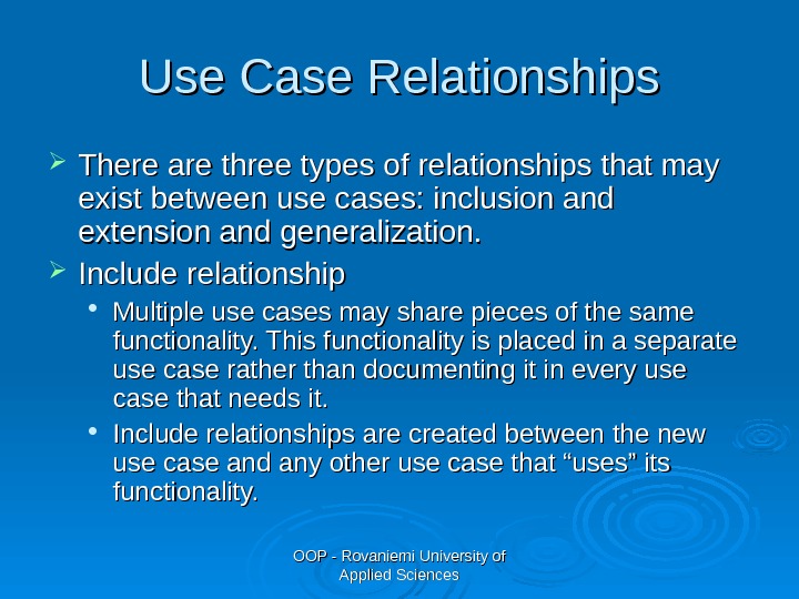
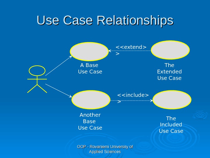
OOP — Rovaniemi University of Applied Sciences. Use Case Relationships There are three types of relationships that may exist between use cases: inclusion and extension and generalization. Include relationship Multiple use cases may share pieces of the same functionality. This functionality is placed in a separate use case rather than documenting it in every use case that needs it. Include relationships are created between the new use case and any other use case that “uses” its functionality.
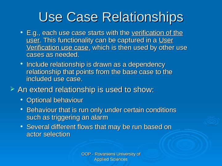
OOP — Rovaniemi University of Applied Sciences. Use Case Relationships E. g. , each use case starts with the verification of the user. This functionality can be captured in a User Verification use case , which is then used by other use cases as needed. Include relationship is drawn as a dependency relationship that points from the base case to the included use case. An extend relationship is used to show: Optional behaviour Behaviour that is run only under certain conditions such as triggering an alarm Several different flows that may be run based on actor selection
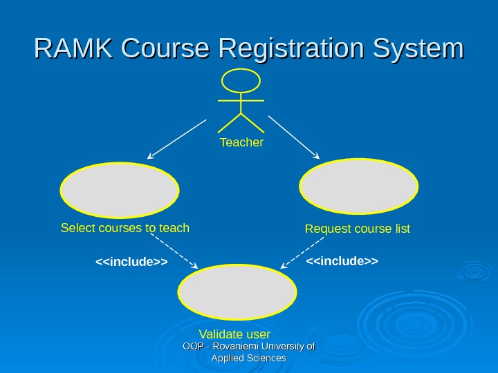
OOP — Rovaniemi University of Applied Sciences. RAMK Course Registration System Teacher Select courses to teach Request course list Validate user<>
OOP — Rovaniemi University of Applied Sciences. Use Case Relationships < > < > The Included Use Case The Extended Use Case. A Base Use Case Another Base Use Case
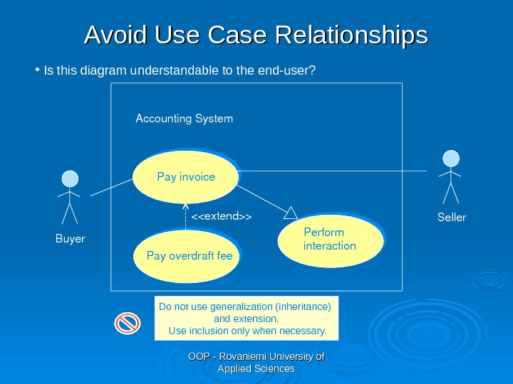
OOP — Rovaniemi University of Applied Sciences. Payoverdraftfee Payinvoice <>Accounting. System Perform interaction. Buyer Seller. Avoid Use Case Relationships Do not use generalization (inheritance) and extension. Use inclusion only when necessary. • Is this diagram understandable to the end-user?
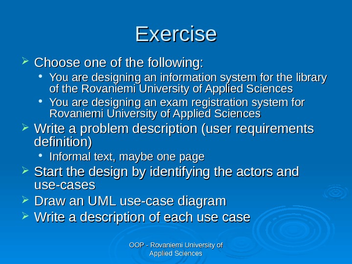
OOP — Rovaniemi University of Applied Sciences. Exercise Choose one of the following: You are designing an information system for the library of the Rovaniemi University of Applied Sciences You are designing an exam registration system for Rovaniemi University of Applied Sciences Write a problem description (user requirements definition) Informal text, maybe one page Start the design by identifying the actors and use-cases Draw an UML use-case diagram Write a description of each use case
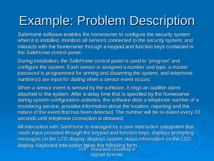
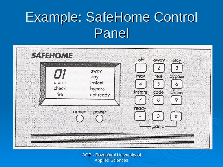
OOP — Rovaniemi University of Applied Sciences. Example: Problem Description Safe. Home software enables the homeowner to configure the security system when it is installed, monitors all sensors connected to the security system, and interacts with the homeowner through a keypad and function keys contained in the Safe. Home control panel. During installation, the Safe. Home control panel is used to “program” and configure the system. Each sensor is assigned a number and type, a master password is programmed for arming and disarming the system, and telephone number(s) are input for dialing when a sensor event occurs. When a sensor event is sensed by the software, it rings an audible alarm attached to the system. After a delay time that is specified by the homeowner during system configuration activities, the software dials a telephone number of a monitoring service, provides information about the location, reporting and the nature of the event that has been detected. The number will be re-dialed every 20 seconds until telephone connection is obtained. All interaction with Safe. Home is managed by a user-interaction subsystem that reads input provided through the keypad and function keys, displays prompting messages on the LCD display, displays system status information on the LCD display. Keyboard interaction takes the following form…
OOP — Rovaniemi University of Applied Sciences. Example: Safe. Home Control Panel
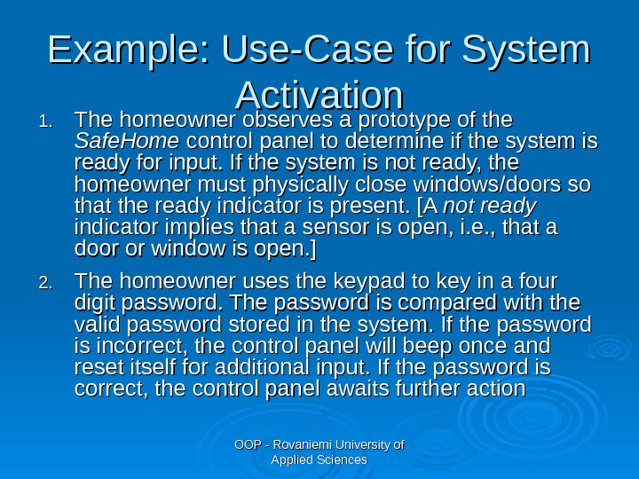
OOP — Rovaniemi University of Applied Sciences. Example: Use-Case for System Activation 1. 1. The homeowner observes a prototype of the Safe. Home control panel to determine if the system is ready for input. If the system is not ready, the homeowner must physically close windows/doors so that the ready indicator is present. [A not ready indicator implies that a sensor is open, i. e. , that a door or window is open. ] 2. 2. The homeowner uses the keypad to key in a four digit password. The password is compared with the valid password stored in the system. If the password is incorrect, the control panel will beep once and reset itself for additional input. If the password is correct, the control panel awaits further action
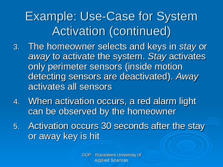
OOP — Rovaniemi University of Applied Sciences. Example: Use-Case for System Activation (continued) 3. 3. The homeowner selects and keys in stay or or away to activate the system. Stay activates only perimeter sensors (inside motion detecting sensors are deactivated). Away activates all sensors 4. 4. When activation occurs, a red alarm light can be observed by the homeowner 5. 5. Activation occurs 30 seconds after the stay or away key is hit
OOP — Rovaniemi University of Applied Sciences. Example: High-Level Use-Case Diagram homeowner Safe Home interacts configures
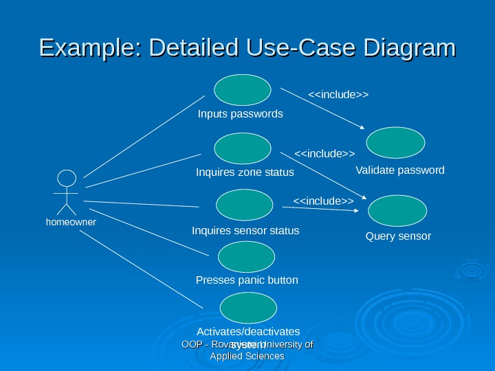
OOP — Rovaniemi University of Applied Sciences. Example: Detailed Use-Case Diagram homeowner Validate password Query sensor. Inputs passwords Inquires zone status Inquires sensor status Presses panic button Activates/deactivates system <>
OOP — Rovaniemi University of Applied Sciences. Tasks for Object-Oriented Analysis 1)1) Basic user requirements must be communicated between customer and software engineer 2)2) Classes must be identified 3)3) A class hierarchy is defined 4)4) Object-to-object relationships should be represented 5)5) Object behaviour must be modeled 6)6) Tasks 1 to 5 are reapplied iteratively until the model is complete Pressman R. , Software Engineering, A Practitioner’s Approach, Sixth Edtion, Mc. Graw-Hill,
OOP — Rovaniemi University of Applied Sciences. Identifying Classes and Objects Identifying objects/classes begins with the examination of the problem statement Objects are determined by underlining each noun or noun clause
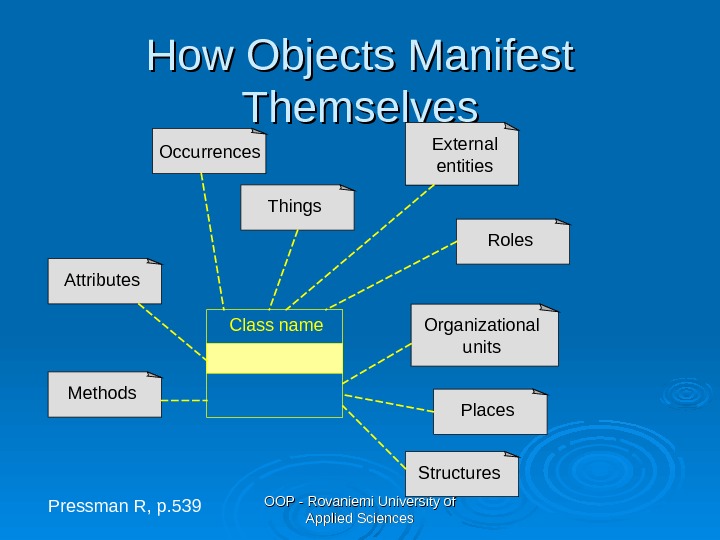
OOP — Rovaniemi University of Applied Sciences. How Objects Manifest Themselves Class name Methods. Attributes Occurrences Things External entities Roles Organizational units Places Structures Pressman R, p.
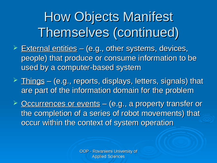
OOP — Rovaniemi University of Applied Sciences. How Objects Manifest Themselves (continued) External entities – (e. g. , other systems, devices, people) that produce or consume information to be used by a computer-based system Things – (e. g. , reports, displays, letters, signals) that are part of the information domain for the problem Occurrences or events – (e. g. , a property transfer or the completion of a series of robot movements) that occur within the context of system operation
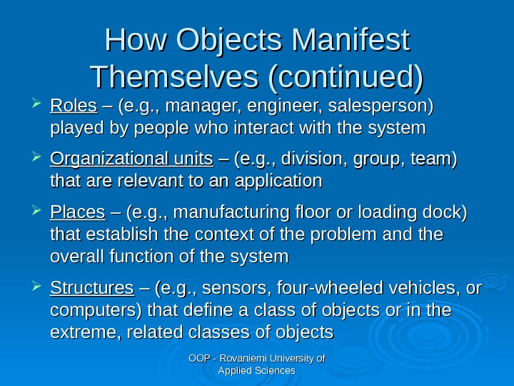
OOP — Rovaniemi University of Applied Sciences. How Objects Manifest Themselves (continued) Roles – (e. g. , manager, engineer, salesperson) played by people who interact with the system Organizational units – (e. g. , division, group, team) that are relevant to an application Places – (e. g. , manufacturing floor or loading dock) that establish the context of the problem and the overall function of the system Structures – (e. g. , sensors, four-wheeled vehicles, or computers) that define a class of objects or in the extreme, related classes of objects
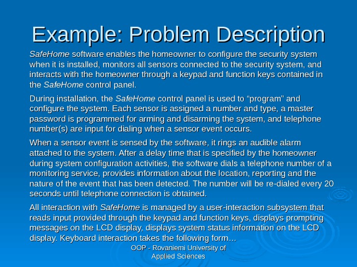
OOP — Rovaniemi University of Applied Sciences. Example: Problem Description Safe. Home software enables the homeowner to configure the security system when it is installed, monitors all sensors connected to the security system, and interacts with the homeowner through a keypad and function keys contained in the Safe. Home control panel. During installation, the Safe. Home control panel is used to “program” and configure the system. Each sensor is assigned a number and type, a master password is programmed for arming and disarming the system, and telephone number(s) are input for dialing when a sensor event occurs. When a sensor event is sensed by the software, it rings an audible alarm attached to the system. After a delay time that is specified by the homeowner during system configuration activities, the software dials a telephone number of a monitoring service, provides information about the location, reporting and the nature of the event that has been detected. The number will be re-dialed every 20 seconds until telephone connection is obtained. All interaction with Safe. Home is managed by a user-interaction subsystem that reads input provided through the keypad and function keys, displays prompting messages on the LCD display, displays system status information on the LCD display. Keyboard interaction takes the following form…
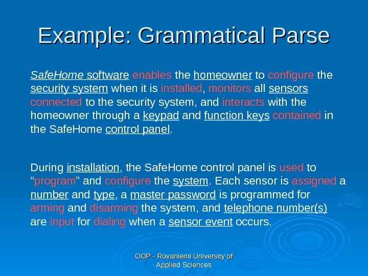
OOP — Rovaniemi University of Applied Sciences. Example: Grammatical Parse Safe. Home software enables the homeowner to configure the security system when it is installed , monitors all sensors connected to the security system, and interacts with the homeowner through a keypad and function keys contained in the Safe. Home control panel. During installation , the Safe. Home control panel is used to “ program ” and configure the system. Each sensor is assigned a number and type , a master password is programmed for arming and disarming the system, and telephone number(s) are input for dialing when a sensor event occurs.
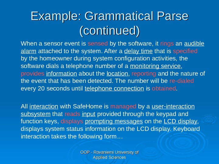
OOP — Rovaniemi University of Applied Sciences. Example: Grammatical Parse (continued) When a sensor event is sensed by the software, it rings an audible alarm attached to the system. After a delay time that is specified by the homeowner during system configuration activities, the software dials a telephone number of a monitoring service , provides information about the location , reporting and the nature of the event that has been detected. The number will be re-dialed every 20 seconds until telephone connection is obtained. All interaction with Safe. Home is managed by a user-interaction subsystem that reads input provided through the keypad and function keys, displays prompting messages on the LCD display , displays system status information on the LCD display. Keyboard interaction takes the following form…
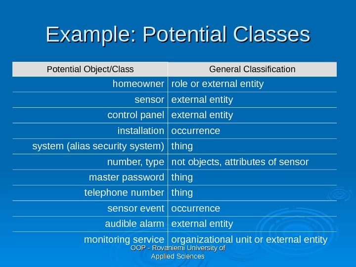
OOP — Rovaniemi University of Applied Sciences. Example: Potential Classes Potential Object/Class General Classification homeowner role or external entity sensor external entity control panel external entity installation occurrence system (alias security system) thing number, type not objects, attributes of sensor master password thing telephone number thing sensor event occurrence audible alarm external entity monitoring service organizational unit or external entity
OOP — Rovaniemi University of Applied Sciences. Group work Analyze the problem description and make a grammatical parse of the text You should identify potential classes (nouns) and operations (verbs) Make a list of potential classes and classify them (external entities, things, etc. )
OOP — Rovaniemi University of Applied Sciences. Selection Characteristics Coad and Yourdon suggest 6 selection characteristics while considering each potential class for inclusion in the analysis model. All of the following must apply. 1. 1. Retained information – the potential class will be useful during analysis only if information about it must be remembered so that the system can function 2. 2. Needed services – the potential class must have a set of identifiable methods that can change the value of its attributes in some way
OOP — Rovaniemi University of Applied Sciences. Selection Characteristics 3. 3. Multiple attributes – during requirement analysis, the focus should be on “major” information; an class with a single attribute may be useful during design, but is probably better represented as an attribute of another class 4. 4. Common attributes – a set of attributes can be defined for the potential class and these attributes apply to all instances of the class
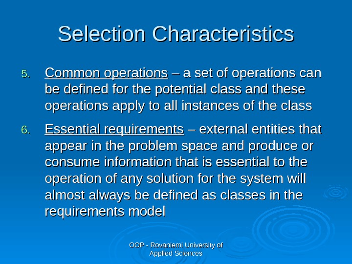
OOP — Rovaniemi University of Applied Sciences. Selection Characteristics 5. 5. Common operations – a set of operations can be defined for the potential class and these operations apply to all instances of the class 6. 6. Essential requirements – external entities that appear in the problem space and produce or consume information that is essential to the operation of any solution for the system will almost always be defined as classes in the requirements model
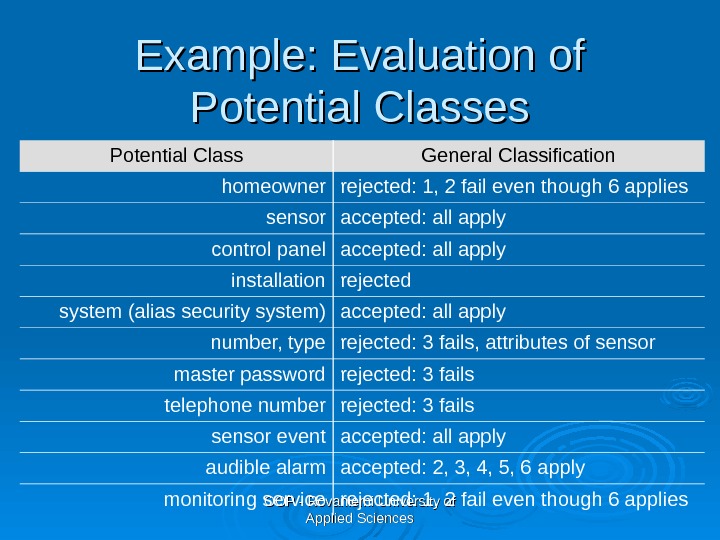
OOP — Rovaniemi University of Applied Sciences. Example: Evaluation of Potential Classes Potential Class General Classification homeowner rejected: 1, 2 fail even though 6 applies sensor accepted: all apply control panel accepted: all apply installation rejected system (alias security system) accepted: all apply number, type rejected: 3 fails, attributes of sensor master password rejected: 3 fails telephone number rejected: 3 fails sensor event accepted: all apply audible alarm accepted: 2, 3, 4, 5, 6 apply monitoring service rejected: 1, 2 fail even though 6 applies
OOP — Rovaniemi University of Applied Sciences. Group Work Analyze potential classes on your list according to the criteria presented on the previous slides. Select the ones, which will be included in the analysis model. ”” Classes struggle, some classes triumph, others are eliminated. ” – Mao Zedong
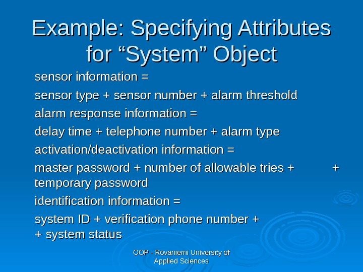
OOP — Rovaniemi University of Applied Sciences. Specifying Attributes describe a class that has been selected for inclusion in the analysis model Study the use cases and the problem description to select the things that “belong” to the class Look for data items that fully define the class and make it unique in the problem context The data items should be refined to elementary level as shown in the following example.
OOP — Rovaniemi University of Applied Sciences. Example: Specifying Attributes for “System” Object sensor information = sensor type + sensor number + alarm threshold alarm response information = delay time + telephone number + alarm type activation/deactivation information = master password + number of allowable tries + + + temporary password identification information = system ID + verification phone number + + system status
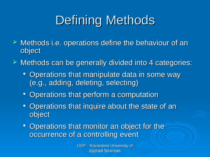
OOP — Rovaniemi University of Applied Sciences. Defining Methods i. e. operations define the behaviour of an object Methods can be generally divided into 4 categories: Operations that manipulate data in some way (e. g. , adding, deleting, selecting) Operations that perform a computation Operations that inquire about the state of an object Operations that monitor an object for the occurrence of a controlling event
OOP — Rovaniemi University of Applied Sciences. Defining Methods Select the methods that reasonably belong to the class To accomplish this, the grammatical parse is studied and verbs are isolated. Some of them will be legitimate methods and can be easily connected to a specific class
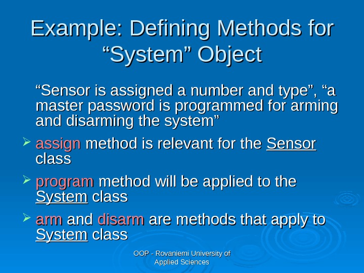
OOP — Rovaniemi University of Applied Sciences. Example: Defining Methods for “System” Object ““ Sensor is assigned a number and type”, “a master password is programmed for arming and disarming the system” assign method is relevant for the Sensor class program method will be applied to the System class armarm and disarm are methods that apply to System class
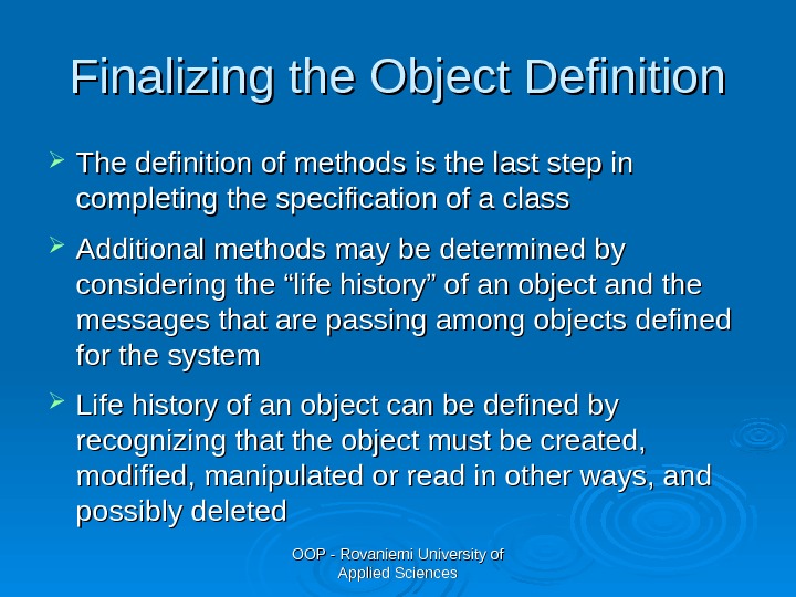
OOP — Rovaniemi University of Applied Sciences. Finalizing the Object Definition The definition of methods is the last step in completing the specification of a class Additional methods may be determined by considering the “life history” of an object and the messages that are passing among objects defined for the system Life history of an object can be defined by recognizing that the object must be created, modified, manipulated or read in other ways, and possibly deleted
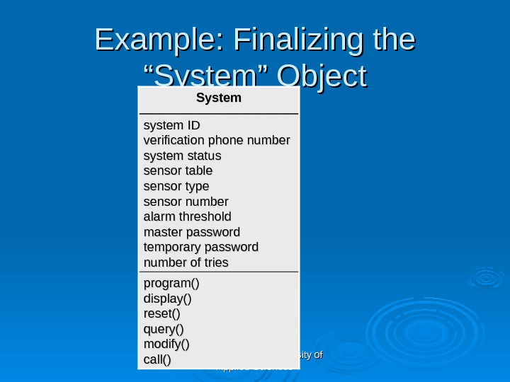
OOP — Rovaniemi University of Applied Sciences. Example: Finalizing the “System” Object program() display() reset() query() modify() call() system ID verification phone number system status sensor table sensor type sensor number alarm threshold master password temporary password number of tries System
OOP — Rovaniemi University of Applied Sciences. Group Work Define attributes and methods for the classes, which you included in your analysis model Remember to refine the data items to elementary level
OOP — Rovaniemi University of Applied Sciences. Tasks for Object-Oriented Analysis 1)1) Basic user requirements must be communicated between customer and software engineer 2)2) Classes must be identified 3)3) A class hierarchy is defined 4)4) Object-to-object relationships should be represented 5)5) Object behaviour must be modeled 6)6) Tasks 1 to 5 are reapplied iteratively until the model is complete Pressman R. , Software Engineering, A Practitioner’s Approach, Sixth Edtion, Mc. Graw-Hill,
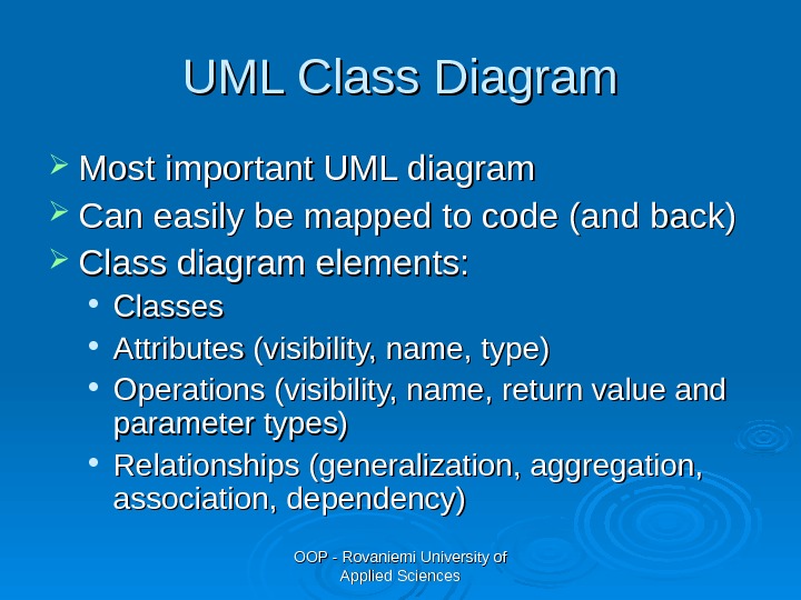
OOP — Rovaniemi University of Applied Sciences. UML Class Diagram Most important UML diagram Can easily be mapped to code (and back) Class diagram elements: Classes Attributes (visibility, name, type) Operations (visibility, name, return value and parameter types) Relationships (generalization, aggregation, association, dependency)
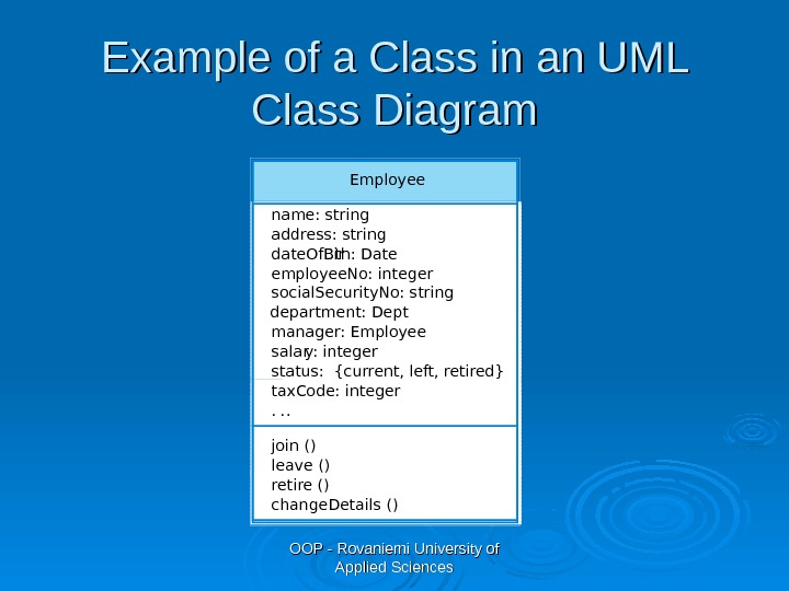
OOP — Rovaniemi University of Applied Sciences. Example of a Class in an UML Class Diagram Employee name: string address: string date. Of. Bir th: Date employee. No: integer social. Security. No: string department: Dept manager: Employee salar y: integer status: {current, left, retired} tax. Code: integer. . . join () leave () retire () change. Details ()
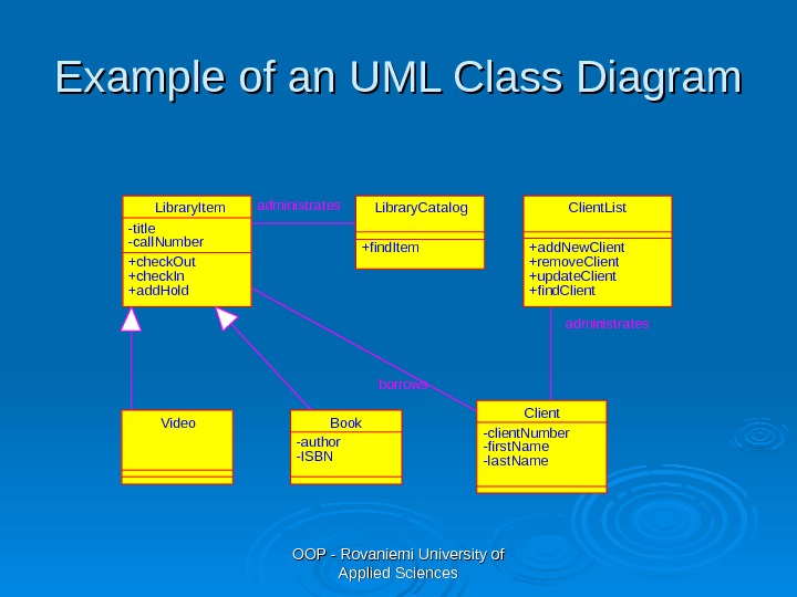
OOP — Rovaniemi University of Applied Sciences. Example of an UML Class Diagram Author Project Status Appr Title Library. System. Class. Diagram. cld Vers File Library. System. Class. Diagram. cld Date 10 -11 -2006 Time 13: 52: 23 -title -call. Number +check. Out +check. In +add. Hold Library. Item +find. Item Library. Catalog -author -ISBN Book. Video +add. New. Client +remove. Client +update. Client +find. Client. List -client. Number -first. Name -last. Name Clientborrowsadministrates
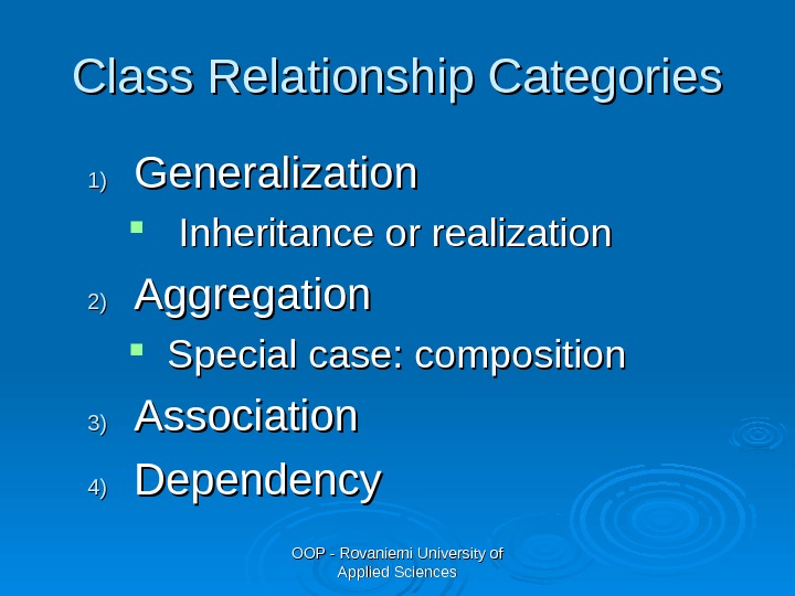
OOP — Rovaniemi University of Applied Sciences. Class Relationship Categories 1)1) Generalization Inheritance or realization 2)2) Aggregation Special case: composition 3)3) Association 4)4) Dependency
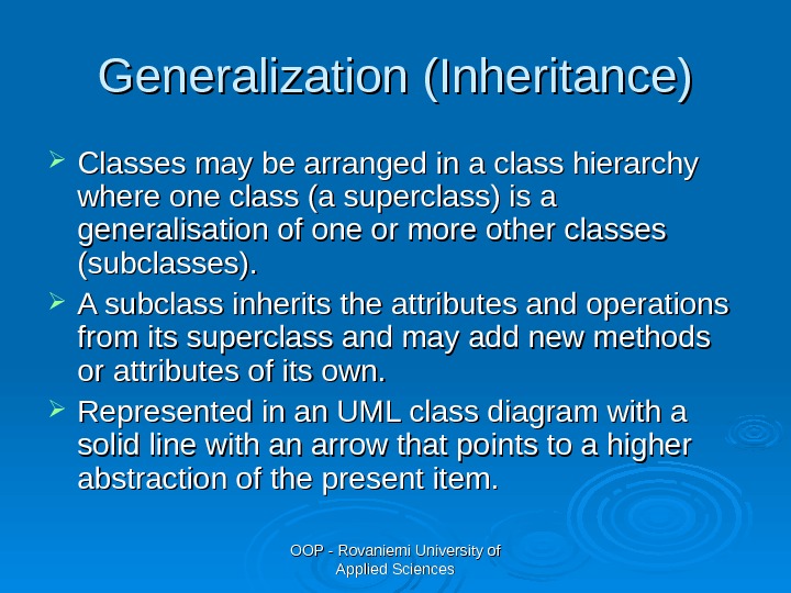
OOP — Rovaniemi University of Applied Sciences. Generalization (Inheritance) Classes may be arranged in a class hierarchy where one class (a superclass) is a generalisation of one or more other classes (subclasses). A subclass inherits the attributes and operations from its superclass and may add new methods or attributes of its own. Represented in an UML class diagram with a solid line with an arrow that points to a higher abstraction of the present item.
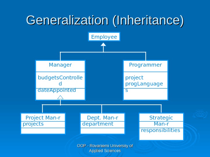
OOP — Rovaniemi University of Applied Sciences. Generalization (Inheritance) Employee Programmer project prog. Language s. Manager budgets. Controlle d date. Appointed Project Man-r projects Dept. Man-r department Strategic Man-r responsibilities
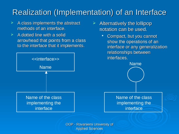
OOP — Rovaniemi University of Applied Sciences. Realization (Implementation) of an Interface A class implements the abstract methods of an interface. A dotted line with a solid arrowhead that points from a class to the interface that it implements. Alternatively the lollipop notation can be used. Compact, but you cannot show the operations of an interface or any generalization relationships between interfaces. Name of the class implementing the interface<> Name of the class implementing the interface Name
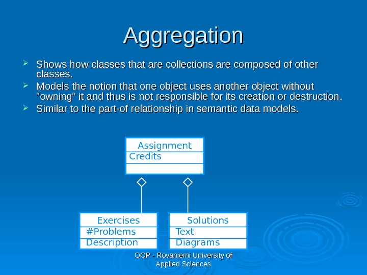
OOP — Rovaniemi University of Applied Sciences. Aggregation Shows how classes that are collections are composed of other classes. Models the notion that one object uses another object without «owning» it and thus is not responsible for its creation or destruction. Similar to the part-of relationship in semantic data models. Assignment Credits Exercises #Problems Description Solutions Text Diagrams
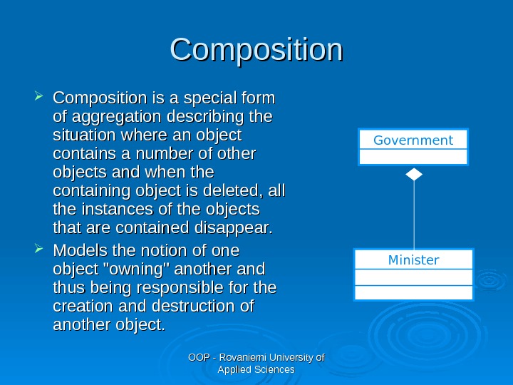
OOP — Rovaniemi University of Applied Sciences. Composition is a special form of aggregation describing the situation where an object contains a number of other objects and when the containing object is deleted, all the instances of the objects that are contained disappear. Models the notion of one object «owning» another and thus being responsible for the creation and destruction of another object. Government Minister
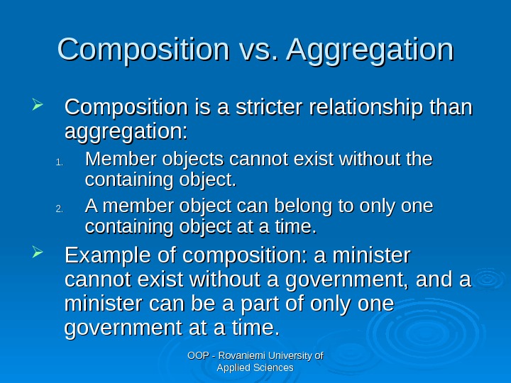
OOP — Rovaniemi University of Applied Sciences. Composition vs. Aggregation Composition is a stricter relationship than aggregation: 1. 1. Member objects cannot exist without the containing object. 2. 2. A member object can belong to only one containing object at a time. Example of composition: a minister cannot exist without a government, and a minister can be a part of only one government at a time.
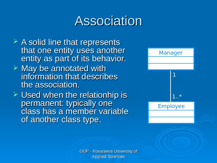
OOP — Rovaniemi University of Applied Sciences. Association A solid line that represents that one entity uses another entity as part of its behavior. May be annotated with information that describes the association. Used when the relationhip is permanent: typically one class has a member variable of another class type. Manager Employee 1 1. . *
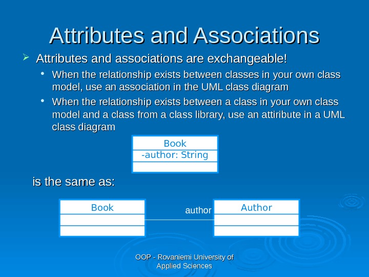
OOP — Rovaniemi University of Applied Sciences. Attributes and Associations Attributes and associations are exchangeable! When the relationship exists between classes in your own class model, use an association in the UML class diagram When the relationship exists between a class in your own class model and a class from a class library, use an attiribute in a UML class diagram Book -author: String is the same as: Book Author author
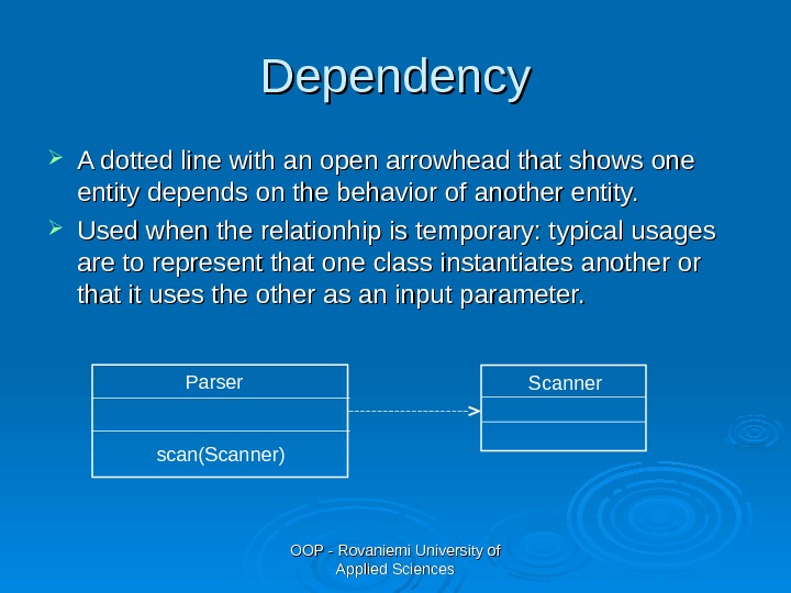
OOP — Rovaniemi University of Applied Sciences. Dependency A dotted line with an open arrowhead that shows one entity depends on the behavior of another entity. Used when the relationhip is temporary: t ypical usages are to represent that one class instantiates another or that it uses the other as an input parameter. Scanner. Parser scan(Scanner)
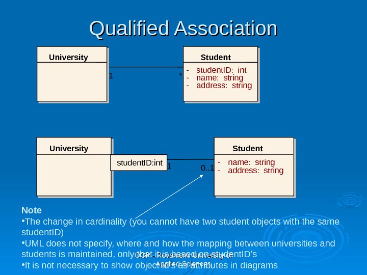
OOP — Rovaniemi University of Applied Sciences. Qualified Association University Student — name: string — address: stringstudent. ID: int 1 0. . 1 University Student — student. ID: int — name: string — address: string 1 * Note • The change in cardinality (you cannot have two student objects with the same student. ID) • UML does not specify, where and how the mapping between universities and students is maintained, only that it is based on student. ID’s • It is not necessary to show object id’s as attributes in diagrams
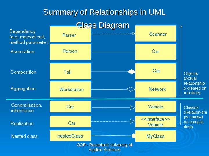
OOP — Rovaniemi University of Applied Sciences. Association Aggregation. Composition Person owns Car Workstation Cat Tail Network Generalization, inheritance Car Vehicle Realization <> Vehicle. Car. Dependency (e. g. methodcall, methodparameter) Parser Scanner. Summary of Relationships in UML Class Diagram 1 1. . * 11 Objects (Actual relationship s created on run-time) Classes (Relation-shi ps created on compile time) nested. Class Nestedclass My. Class
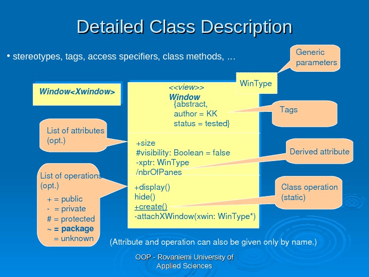
OOP — Rovaniemi University of Applied Sciences <> Window {abstract, author=KK status=tested} +size #visibility: Boolean=false xptr: Win. Type /nbr. Of. Panes +display() hide() +create() attach. XWindow(xwin: Win. Type*)+=public =private #=protected ~=package =unknown. Listofoperations (opt. ) (Attributeandoperationcanalsobegivenonlybyname. ) Win. Type Window Classoperation (static)Tags Generic parameters Listofattributes (opt. ) • stereotypes, tags, access specifiers, class methods, … Derivedattribute. Detailed Class Description
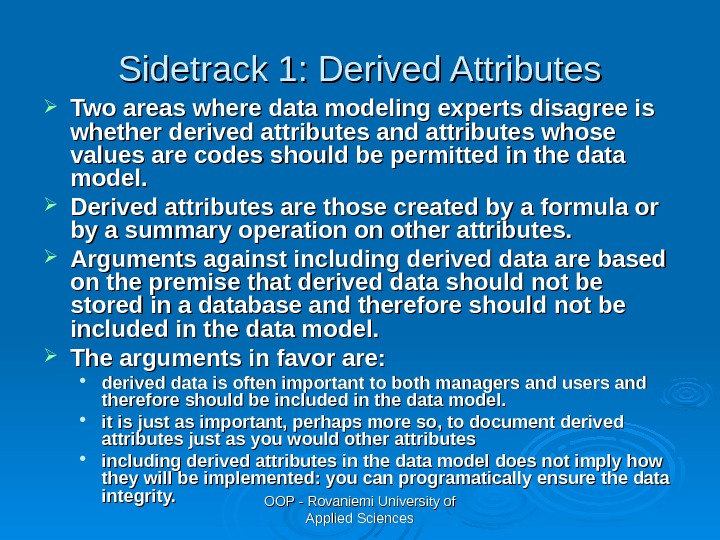
OOP — Rovaniemi University of Applied Sciences. Sidetrack 1: Derived Attributes Two areas where data modeling experts disagree is whether derived attributes and attributes whose values are codes should be permitted in the data model. Derived attributes are those created by a formula or by a summary operation on other attributes. Arguments against including derived data are based on the premise that derived data should not be stored in a database and therefore should not be included in the data model. The arguments in favor are: derived data is often important to both managers and users and therefore should be included in the data model. it is just as important, perhaps more so, to document derived attributes just as you would other attributes including derived attributes in the data model does not imply how they will be implemented: you can programatically ensure the data integrity.
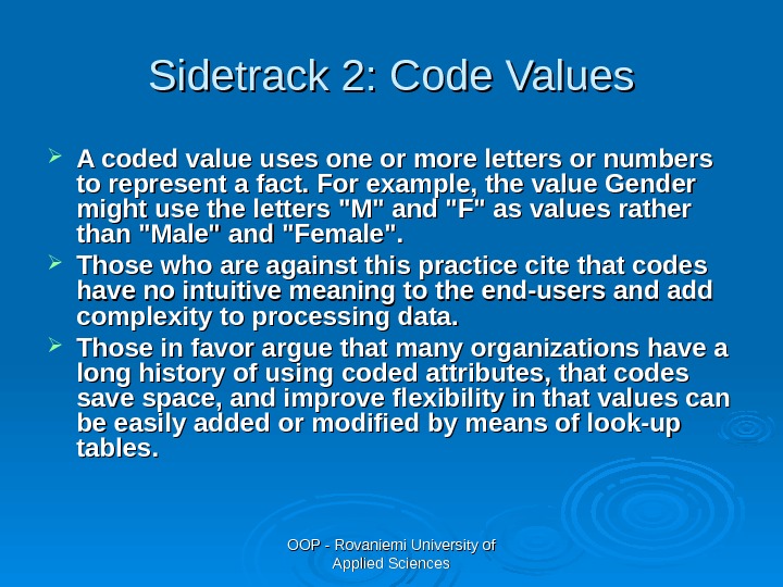
OOP — Rovaniemi University of Applied Sciences. Sidetrack 2: Code Values A coded value uses one or more letters or numbers to represent a fact. For example, the value Gender might use the letters «M» and «F» as values rather than «Male» and «Female». Those who are against this practice cite that codes have no intuitive meaning to the end-users and add complexity to processing data. Those in favor argue that many organizations have a long history of using coded attributes, that codes save space, and improve flexibility in that values can be easily added or modified by means of look-up tables.
OOP — Rovaniemi University of Applied Sciences. Group Work Draw an UML class diagram of the classes, which you included in your analysis model.
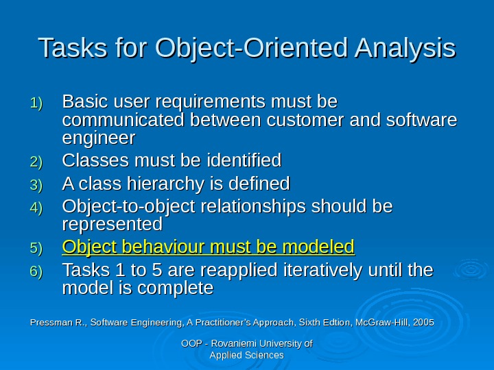
OOP — Rovaniemi University of Applied Sciences. Tasks for Object-Oriented Analysis 1)1) Basic user requirements must be communicated between customer and software engineer 2)2) Classes must be identified 3)3) A class hierarchy is defined 4)4) Object-to-object relationships should be represented 5)5) Object behaviour must be modeled 6)6) Tasks 1 to 5 are reapplied iteratively until the model is complete Pressman R. , Software Engineering, A Practitioner’s Approach, Sixth Edtion, Mc. Graw-Hill,
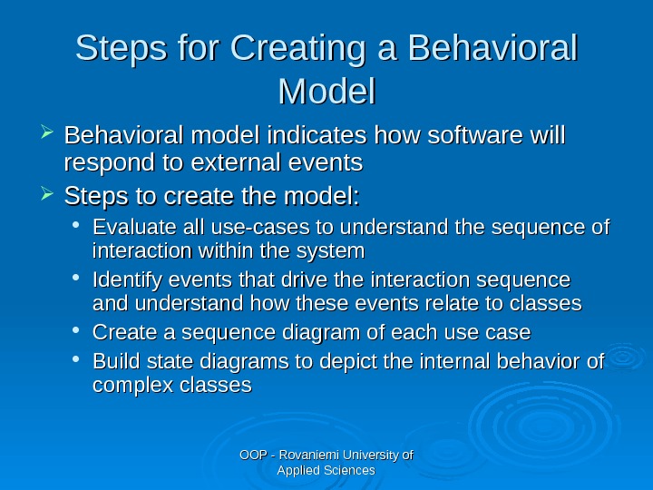
OOP — Rovaniemi University of Applied Sciences. Steps for Creating a Behavioral Model Behavioral model indicates how software will respond to external events Steps to create the model: Evaluate all use-cases to understand the sequence of interaction within the system Identify events that drive the interaction sequence and understand how these events relate to classes Create a sequence diagram of each use case Build state diagrams to depict the internal behavior of complex classes
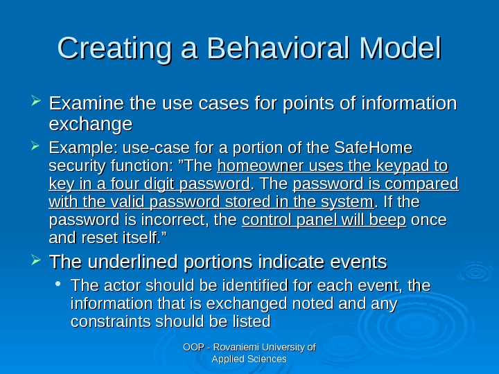
OOP — Rovaniemi University of Applied Sciences. Creating a Behavioral Model Examine the use cases for points of information exchange Example: use-case for a portion of the Safe. Home security function: ”The homeowner uses the keypad to key in a four digit password. The password is compared with the valid password stored in the system. If the password is incorrect, the control panel will beep once and reset itself. ” The underlined portions indicate events The actor should be identified for each event, the information that is exchanged noted and any constraints should be listed
OOP — Rovaniemi University of Applied Sciences. Creating a Behavioral Model Once all events have been identified, they are allocated to the objects involved Put the objects to a sequence diagram (object name: class name) Messages show how events cause flow from one object to another. Use arrows to indicate messages between objects in the diagram.
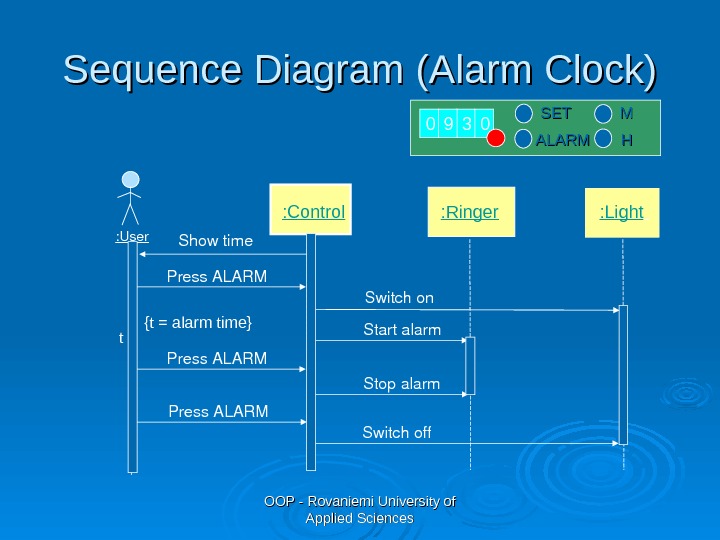
OOP — Rovaniemi University of Applied Sciences SETSET ALARM MM HH : Ringer Switchon : Light Press. ALARM Showtime: User : Control Startalarm Press. ALARM Stopalarm Press. ALARM Switchoff 0 9 3 0 t {t = alarm time}Sequence Diagram (Alarm Clock)
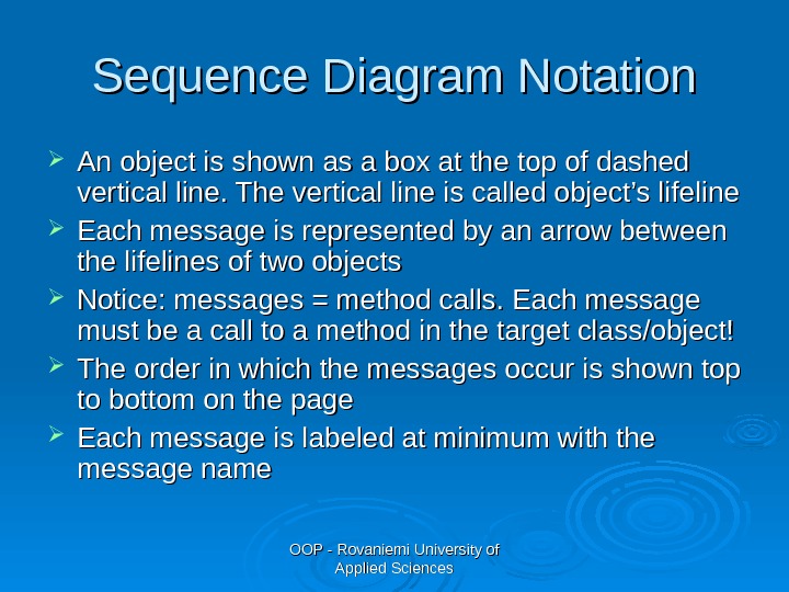
OOP — Rovaniemi University of Applied Sciences. Sequence Diagram Notation An object is shown as a box at the top of dashed vertical line. The vertical line is called object’s lifeline Each message is represented by an arrow between the lifelines of two objects Notice: messages = method calls. Each message must be a call to a method in the target class/object! The order in which the messages occur is shown top to bottom on the page Each message is labeled at minimum with the message name
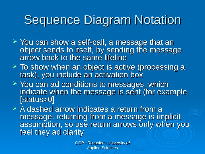
OOP — Rovaniemi University of Applied Sciences. Sequence Diagram Notation You can show a self-call, a message that an object sends to itself, by sending the message arrow back to the same lifeline To show when an object is active (processing a task), you include an activation box You can ad conditions to messages, which indicate when the message is sent (for example [status>0] A dashed arrow indicates a return from a message; returning from a message is implicit assumption, so use return arrows only when you feel they ad clarity
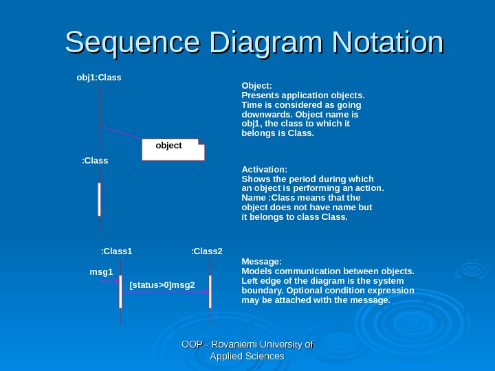
OOP — Rovaniemi University of Applied Sciences. Sequence Diagram Notation obj 1: Class object Object: Presents application objects. Time is considered as going downwards. Object name is obj 1, the class to which it belongs is Class. lifeline : Class Activation: Shows the period during which an object is performing an action. Name : Class means that the object does not have name but it belongs to class Class. : Class 1 : Class 2 [status>0]msg 2 msg 1 Message: Models communication between objects. Left edge of the diagram is the system boundary. Optional condition expression may be attached with the message.
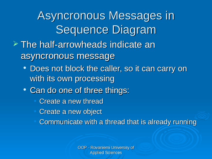
OOP — Rovaniemi University of Applied Sciences. Asyncronous Messages in Sequence Diagram The half-arrowheads indicate an asyncronous message Does not block the caller, so it can carry on with its own processing Can do one of three things: • Create a new thread • Create a new object • Communicate with a thread that is already running
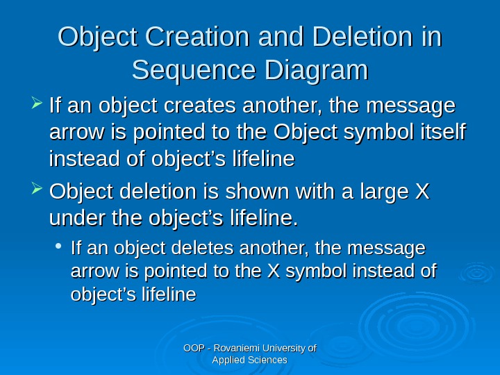
OOP — Rovaniemi University of Applied Sciences. Object Creation and Deletion in Sequence Diagram If an object creates another, the message arrow is pointed to the Object symbol itself instead of object’s lifeline Object deletion is shown with a large X under the object’s lifeline. If an object deletes another, the message arrow is pointed to the X symbol instead of object’s lifeline
OOP — Rovaniemi University of Applied Sciences. Group Work Choose one of the use cases you defined earlier and draw a sequence diagrams of it according to the guidelines given on the previous slides. Start by identifying the events and after that allocate them to objects.
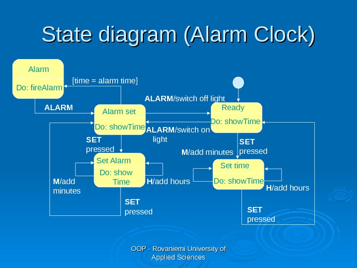
OOP — Rovaniemi University of Applied Sciences SET pressed. Do: show. Time Ready M /add minutes H /add hours SET pressed[time = alarm time] Alarm set. Alarm Do: fire. Alarm ALARM /switch on light. ALARM /switch off light Set time Do: show. Time. Set Alarm Do: show Time. ALARM SET pressed Do: show. Time M /add minutes H /add hours SET pressed. State diagram (Alarm Clock)
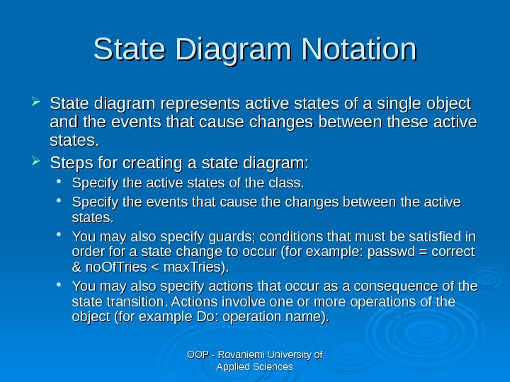
OOP — Rovaniemi University of Applied Sciences. State Diagram Notation State diagram represents active states of a single object and the events that cause changes between these active states. Steps for creating a state diagram: Specify the active states of the class. Specify the events that cause the changes between the active states. You may also specify guards; conditions that must be satisfied in order for a state change to occur (for example: passwd = correct & no. Of. Tries < max. Tries). You may also specify actions that occur as a consequence of the state transition. Actions involve one or more operations of the object (for example Do: operation name).
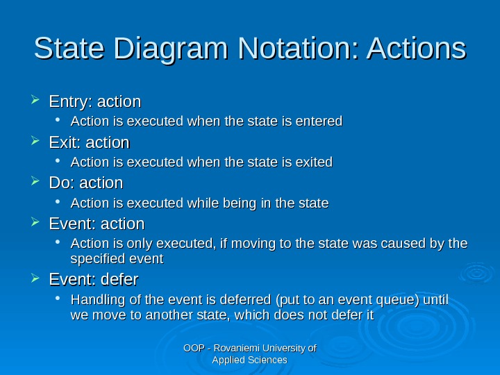
OOP — Rovaniemi University of Applied Sciences. State Diagram Notation: Actions Entry: action Action is executed when the state is entered Exit: action Action is executed when the state is exited Do: action Action is executed while being in the state Event: action Action is only executed, if moving to the state was caused by the specified event Event: defer Handling of the event is deferred (put to an event queue) until we move to another state, which does not defer it
OOP — Rovaniemi University of Applied Sciences. Summary Sequence diagram shows typical interactions between domain objects. State diagram shows the different states of a domain object. More on UML in Software Engineering course.
OOP — Rovaniemi University of Applied Sciences. Group Work Choose one of the classes you defined earlier and create a state diagram of its behaviour according to the guidelines given on the previous slides. Example: we have a class Book in a library system. A Book object can be in the following states: On shelf, Checked out, Returned on hold, Checked out with hold. Draw an UML state diagram showing the states and state transitions.
OOP — Rovaniemi University of Applied Sciences”” Travel light” Build only those models that provide value — no more, no less. Perfection is reached, not when there is no longer anything to add, but when there is no longer anything to take away. (A. Saint-Exupery)