

9effd03c4b498d8d8fb4c05610e0fde9.ppt
- Количество слайдов: 97
 NON-DESTRUCTIVE TESTING Examination of materials and components in such a way that allows material to be examinated without changing or destroying their usefulness
 NDT Methods • • • Penetrant Inspection Magnetic Particle Inspection Eddy Current Inspection Ultrasonic Inspection Radiographic Inspection • Magnetic Flux Leakage • Acoustic Emission
 Introduction § Non Destructive Testing involves techniques based on application of physical principles employed for purpose of determining characteristics of materials or components and for detecting and assessing inhomogeneity and harmful defects without changing the usefulness of materials or components. § The methods used may be simple or intricate. § It plays a vast role in quality control of finished product. § Skilled judgments and experience is required while performing NDT. Devang Gandhi
 Advantages 1. Flaw Detection and Evaluation 2. Leak Detection in Components 3. Location Determination and Orientation of Defects 4. Dimensional Measurements 5. Structure and Microstructure Characterization 6. Estimation of Mechanical Properties 7. Material Sorting and Chemical Composition 8. Assistance in Product Development Devang Gandhi 9. Improve and control Manufacturing Process
 Industrial Use § Inspection of Raw Products – Forgings, Castings, Extrusions. § Inspection following Secondary Processing – Machining, Welding, Grinding, Heat Treatment, Plating. § Inspection for In-Service Damage – Cracking, Corrosion, Erosion/Wear, Heat Damage. Devang Gandhi
 Types of NDT Visual Examination Liquid Penetrant Testing Magnetic Particle Testing Eddy Current Testing Radiography Ultrasonic Testing Devang Gandhi
 Visual Examination § Primary method of NDT § A simple visual test reveals gross surface defects. § Physical Principle : Illumination of the test specimen with light. § Equipments used are very simple and portable. § Most Valuable NDT Tool – Human Eye. § Mainly performed to obtain the general condition of components. Devang Gandhi
 Methodology Use of Optical Instruments : Magnify defects, permit visual checks of inaccessible areas, presence of foreign objects, formation of corrosive layer or even damage. Instruments for Visual Examination
 Applications § Inspection of plant components for leakage. § Misalignment in equipment parts. § Corrosion, erosion, cracks, fracture. § Minute discontinuities on parts like pumps, compressors. Limitations § Detects only surface defects. § Cannot be used at places with bright exposure or no light. § Equipments cannot be exposed to hazardous places. Devang Gandhi
 Penetrant Inspection
 Penetrant Flaw Detection (PFD)") Liquid Penetrant Inspection A. K. A. Dye Penetrant Inspection (DPI) Penetrant Flaw Detection (PFD) Penetrant testing (PT) • Surface inspection method • Applicable to all non-porous, non-absorbing materials
Liquid Penetrant Inspection A. K. A. Dye Penetrant Inspection (DPI) Penetrant Flaw Detection (PFD) Penetrant testing (PT) • Surface inspection method • Applicable to all non-porous, non-absorbing materials
 Penetrant Inspection • Penetrating fluid applied to component and drawn into defect by capillary action • Penetrating fluid removed from component surface (but not from defect)
 Penetrant Inspection • Developer applied to surface • Penetrant drawn back out of the defect by reverse capillary action
 Principle : Capillary Action • Interaction of adhesive forces(wetting side of the sides of the tubes) and cohesive forces(surface tension of the liquid)
 1. PREPARATION AND PRE-CLEANING 2. PENETRANT APPLICATION 3. REMOVAL OF EXCESS PENETRANT 4. DEVELOPING 5. INSPECTION 6. POST TEST CLEANING
 What will happen if cleaning is not been done properly ? • The penetrant is not be able to wet the surface of the test object • The penetrant is unable to enter a discontinuity due to a blockage • The bleed out of the penetrant from a discontinuity is restricted
 CLEANING METHODS MECHANICAL METHODS E. G BRUSHING, BLASTING CHEMICAL METHODS E. G HOT SOLVING DEGREASING, ACID PICKLING
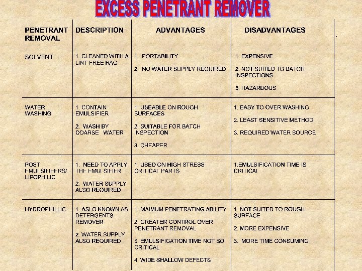
 System classification • PENETRANT • • Colour • contrast • • Fluorescent • Dual • REMOVAL Solvent Water washable Post emulsifiable • • DEVELOPERS Dry powder Aqueous Non-Aqueous
 TYPE OF PENETRANT • COLOUR CONTRAST PENETRANT • FLOURESENT PENETRANT • DUAL PENETRANT
 APPLICATION OF PENETRANT • • DIPPING AND DRAINING SPRAYING ELECTO-STATIC SPRAY BRUSHING
 Qualities of penetrant • • • High surface tension Good wetting ability Specific gravity lower than 1 Penetrant will not damaged the test piece Non-toxic High flash point Low volatility Visible in small quantities Post -cleaning should be easy
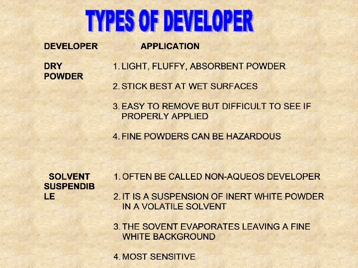
 ESSENTIAL FEATURES OF DEVELOPER • ABSORBENT TO DRAW PENETRANT OUT OF DEFECT • FINE GRAINED AND NOT LUMPY • ABLE TO MASK THE BACK GROUND BUT NOT THICK ENOUGH TO MASK A DEFECT • LIGHT AND EASY APPLICABLE • EASILY WET BY PENETRANT • EASILY REMOVED FROM THE SPECIMEN • INERT AND NON-TOXIC
 WATER SUSPENDIBLE WATER SOLUBLE 1. IT IS A WHITE POWDER AND THEN MIXED WITH WATER IN SUFFACTANT ADDED 2. NOT OFTEN BE USED 3. THE POWDER WILL DRAWS THE PENETRANT OUT OF DEFECT WHEN THE WATER EVAPORATES 4. USE AS IN CONCENTRATED IN COLOUR CONTRAST PENETRANT, THINNER FORM IN FLOURESENT 1. SOLUTION OF SALTS IN FORMS OF FINE GRANULES WHICH DISSOLVED IN WATER 2. SUITABLY FOR FLUORESCENT PENETRANT
 Advantages of DPI • VERY SENSITIVE • CAN BE USED ON NON-FERROUS METALS, SOME PLASTICS AND GLASS • SMALL OBJECTS WITH COMPLEX GEOMETRY CAN BE INSPECTED • NO NEED POWER SUPPLY • NOT REQUIRED GREAT SKILLED • CAN BE APPLIED IN BATCHES
 Disadvantages of DPI • DEFECTS OPEN TO THE SURFACE ONLY CAN BE DETECTED • SURFACE PREPARATION IS CRITICAL • THE METHOD TAKES TIME • MESSY • INTERPRETATION SOMETIMES DIFFICULT • DO NOT APPLIED TO PAINTED OBJECTS • EFFLUENT PROBLEM WITH WASTE
 Magnetic Particle Inspection
 Magnetic Particle Inspection • Test method for the detection of surface and sub-surface indications in ferromagnetic materials • Magnetic field induced in component • Defects disrupt the magnetic flux • Defects revealed by applying ferromagnetic particles
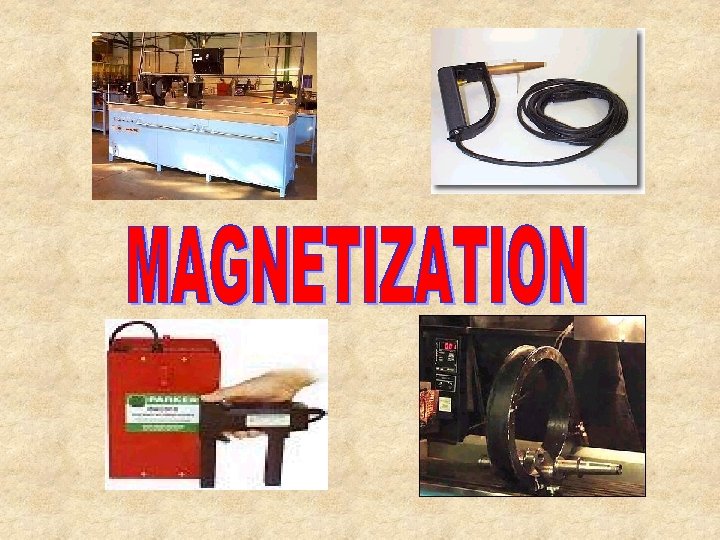
 PRINCIPLE OF MPI • MAGNETIZING THE SPECIMEN TO AN ADEQUATE FLUX DENSITY • APPLYING FINE FERROMAGNETIC PARTICLES OVER THE SURFACE OF THE SPECIMEN • BEING ABLE TO SEE CLUSTERS OF THE MAGNETIC PARTICLES THAT GATHER AT FLUX LEAKAGES AS AN INDICATION TO THE FLAW
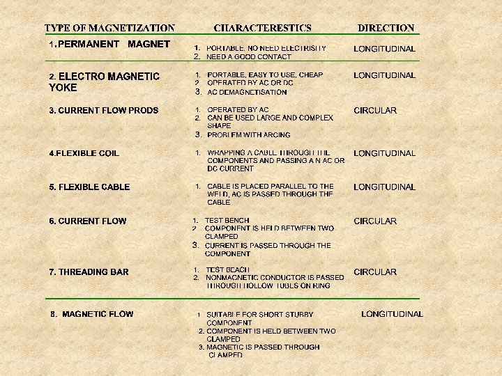
 : Flux Leakage No Defect N Defect S N S Lines") Principle of MPI(1) : Flux Leakage No Defect N Defect S N S Lines of flux follow the path of least resistance
Principle of MPI(1) : Flux Leakage No Defect N Defect S N S Lines of flux follow the path of least resistance
: FLUX LEAKAGE • The magnetic flux lines IDEALLY at the right") PRINCIPLE OF MPI(2): FLUX LEAKAGE • The magnetic flux lines IDEALLY at the right angle(90°) to a flaw to give the best indication. • The minimum orientation of the flaws to the magnetic flux to be detected is 45 degree
PRINCIPLE OF MPI(2): FLUX LEAKAGE • The magnetic flux lines IDEALLY at the right angle(90°) to a flaw to give the best indication. • The minimum orientation of the flaws to the magnetic flux to be detected is 45 degree
 Magnetic Flux Leakage • A saturation of flux is introduced N S
 Magnetic Flux Leakage • A saturation of flux is introduced • Flux forced into air by reductions in thickness N S
 Magnetic Flux Leakage • A saturation of flux is introduced • Flux forced into air by reductions in thickness • Magnetic flux detected by sensors Sensor N S
 Magnetic Flux Leakage Affected by • Climatic conditions • Cleanliness • Surface condition Limitations • Coverage • Qualitative not Quantitative • Top side / Bottom side differentiation
 • • • PRECLEANING MAGNETISATION APPLYING THE DETECTING MEDIA INSPECTION DEMAGNETISATION POST-TEST CLEANING
 PRE-CLEANING • NOT BE SO THROUGHT AS FOR LIQUID PENETRANT INSPECTION • MPI SHOULD NOT BE CARRIED OUT THROUGHT NON-MAGNETIC COATING THICKER THAN 50 MICROMETERS
 DETECTING MEDIA • CAN BE INKS OR POWDER • MADE FROM HIGHLY PERMEABLE MATERIAL • FERRIC OXIDE IS USED FOR INKS, SUSPENDIBLE IN LIQUID, KEROSINE BASED OR WATER • POWDERS APPLICABLE TO SITE WORK SUCH AS WELD OR CASTING. CAN BE USED ON HOT COMPONENTS
 CONTROL CHECKS CASTROL STRIPS/ PIE GAUGE BLACK LIGHT U. V LIGHT METER FIELD INDICATOR KETOS RING CENTRIFUGAL TUBES
 CONTROL CHECK LIST DURATION REQUIREMENT DAILY 1. 25 -3. 5% NON-FLOURESENT INK INTENSITY DAILY COMPARISON BETWEEN NEW AND OLD ONE CARRIER LIQUID CHECKED DAILY COMPARISON BETWEEN NEW AND OLD ONE CURRENT FLOW FACILITY DAILY DEPENDING ONPROCEDURE MAGNETIC FLOW FACILITY DAILY DEPENDING ONPROCEDURE TANK LEVEL DAILY DEPENDING ONPROCEDURE UV LIGHT INTENSITY WEEKLY AMBIENT LIGHT INTENSITY WEEKLY U. V LIGHT LAMP MONTHLY INK SETTELEMENT 0. 1 -0. 3 % FLOURESENT 0. 8 MILIWATTS/ SQUARE CM 500 LUX BLACK INK 10 LUX FLOURESENT SAFETY AND CLEANLINESS
 Advantages of MPI • • • Will detect some sub-surface defects Rapid and simple to understand Pre-cleaning not as critical as with DPI Will work through thin coatings Cheap rugged equipment Direct test method
 Disadvantages of MPI • • • Ferromagnetic materials only Requirement to test in 2 directions Demagnetisation may be required Odd shaped parts difficult to test Not suited to batch testing Can damage the component under test
 Ultrasonic Inspection Principle • High frequency sound waves are introduced into a material • Interfaces between materials of differing acoustic properties reflect or transmit sound • Reflected sound is displayed on a CRT
 Defect Orientation 0 degree Probes Screen Depth Metal Depth
") Defect Orientation Angle Probes Range Depth = Range x Cos (Probe angle)
Defect Orientation Angle Probes Range Depth = Range x Cos (Probe angle)
 Defect Orientation 1 2 3
 Advantages • Sensitive to cracks at various orientations • Portability • Safety • Able to penetrate thick sections • Measures depth and through wall extent
 • Not easily applied to complex geometries") Disadvantages • No permanent record (unless automated) • Not easily applied to complex geometries and rough surfaces. • Unsuited to course grained materials • Requires highly skilled and experienced technicians
Disadvantages • No permanent record (unless automated) • Not easily applied to complex geometries and rough surfaces. • Unsuited to course grained materials • Requires highly skilled and experienced technicians
 Radiographic Inspection • Electromagnetic radiation is imposed upon a test object • Radiation is transmitted to varying degrees dependant upon the density of the material through which it is travelling • Variations in transmission detected by photographic film or fluorescent screens • Applicable to metals, non-metals and composites
 Radiographic Inspection Radiation Source Lower density Specimen Film Higher density
 Industrial radiography Ultra violet 10 -10 10 -8 10 -6 Electric Waves Microwaves Infra red TV 10 -4 10 -2 1 cm 102 Wavelength 104 106 108
 Shorter Wavelength = Increased Energy Shortening Wavelength
 X-Ray Production TUNGSTEN C U R R E N T TARGET -ve FOCUSING CUP +ve X-RAY
 X-RAY PRODUCTION • CATHODE • ANODE 1. PROCESS THAT MAKE THE ELECTRON BOILS OUT FROM THE HOT WIRE IS CALLED THERMIONIC EMISSION 1. INCLINED TUNGSTEN TARGET EMBEDDED IN A LARGE LUMP OF COPPER 2. IT IS CONTROLLED BY THE MILIAMP CONTROL THAT SUPPLY CURRENT TO THE CATHODE 3. INCREASED THE CURRENT, WILL INCREASED THE INTENSITY OF THE ELECTRON STREAM AND HENCE THE RADIATION 2. USED AS A TARGET FOR THE ELECTRON TO HIT, AND THE IMPACT WILL PRODUCE X-RAYS AND HEAT. 3. VOLTAGE THAT SUPPLY TO THE ANODE IS CONTROLED BY THE k. V CONTROL. 4. THE HIGHER THE VOLTAGE ACROSS THE TUBE, THE HIGHER THE VELOCITY OF THE ELECTRONS AND THE GREATER THE PENETRATING POWER
 X-Ray Production Amperage Increase filament temperature Increase number of electrons Increase amount of radiation Decrease filament temperature Decrease number of electrons Decrease amount of radiation
 X-Ray Production Kilovoltage Increase Decrease Increase electron speed Decrease electron speed Radiation wavelength shortens Radiation wavelength increases Increase penetration Decrease penetration
 Factors Influencing Sensitivity - MEASURE OF ACCURANCY OF THE RADIOGRAPHY Contrast - COMPARISON BETWEEN FILM DENSITIES Definition - LINE OF DEMARCATION BETWEEN AREAS OF DIFFERENT DENSITIES
 Factors Influencing Sensitivity Contrast Density Film Energy Definition Object contrast Processing
 Factors Influencing Sensitivity Contrast Density Time Film Energy Temperature Definition Object contrast Type Strength Processing Agitation
 Factors Influencing Sensitivity Contrast Film speed Screens Energy Definition Vibration Geometry Processing
 Factors Influencing Sensitivity Contrast Film speed Time Screens Energy Temperature Definition Vibration Geometry Type Strength Processing Agitation
") • CALCULATE USING PENETRAMETER OR IMAGE QUALITY INDICATION (IQI)
• CALCULATE USING PENETRAMETER OR IMAGE QUALITY INDICATION (IQI)
 Advantages of Radiography • • • Permanent record Internal flaws Can be used on most materials Direct image of flaws Real - time imaging
 Disadvantages of Radiography • • Health hazard Sensitive to defect orientation Limited ability to detect fine cracks Access to both sides required Limited by material thickness Skilled interpretation required Relatively slow High capital outlay and running costs
 Radioactive isotope • It is small, typically 1 mm x 1. 5 mm cylinders, that give off gamma rays • It occurs in nature and also in artificial isotopes • Artificial isotopes are created by bombarding an element with an excess of neutron in the nuclear reactor. • Example of nature isotopes are radium and uranium • Example of artificial isotopes are iridium 192 and cobalt 60
 MEASUREMENT OF RADIOACTIVITY • THE BASIC UNIT IS CURIE • IN SI UNIT, IT IS MEASURED IN BECQUEREL • 1 CURIE = 3. 7 X 10¹⁰ BECQUERELS • HALF LIFE OF AN ISOTOPE IS THE TIME IT TAKES FOR 1/2 OF THE ATOMS TO DECAY
 CALCULATE THE EXPOSURE TIME FOR GAMMA RADIOGRAPHY • BY USING THE FORMULA BELOW ; T = EF X I 2 D T = EXPOSURE TIME, SEC D = SOURCE TO FILM DISTANCE, IN I = INTENSITY OF THE SOURCE, CURIE EF = EXPOSURE FACTOR, REFER TO THE EXPOSURE CHART
 ISOTOPE CAMERA OR PROJECTOR OPERATION OF A TYPICAL ISOTOPE CAMERA
 SAFE DISTANCE GIVEN BY THE FORMULA BELOW: = CURIES X 4. 8 X 1000 1/2 7. 5 THIS GIVES DISTANCE IN METERS • BARRIERS MUST BE ERECTED BEYOND THE SAFE DISTANCE
 RADIOGRAPHIC FILM • IT HAS TWO TYPES BASICALLY: SLOW FILM - FINE GRAIN AND NEED MORE EXPOSURE FAST FILM - LARGE GRAINS AND NEED LESS EXPOSURE • KNOWLEDGE OF FILM CAN HELPS THE RADIOGRAPHER TO WORK OUT EXPOSURES WHEN CHANGING FILM BRANDS. E. G IN TABLE 5. 3 • FILM ALSO SHOULD BE STORED IN EDGES IN COOL DRY CONDITIONS AWAY FROM CHEMICALS AND RADIATION
 • Double Wall Single Image(DWSI) • Double") Radiographic Techniques • Single Wall Single Image(SWSI) • Double Wall Single Image(DWSI) • Double Wall Double Image(DWDI)
Radiographic Techniques • Single Wall Single Image(SWSI) • Double Wall Single Image(DWSI) • Double Wall Double Image(DWDI)
 Panoramic") Radiographic Techniques • Single Wall Single Image(SWSI) Panoramic
Radiographic Techniques • Single Wall Single Image(SWSI) Panoramic
 • Double Wall Single Image(DWSI)") Radiographic Techniques • Single Wall Single Image(SWSI) • Double Wall Single Image(DWSI)
Radiographic Techniques • Single Wall Single Image(SWSI) • Double Wall Single Image(DWSI)
 • Double Wall Single Image(DWSI) • Double") Radiographic Techniques • Single Wall Single Image(SWSI) • Double Wall Single Image(DWSI) • Double Wall Double Image(DWDI) OFFSET
Radiographic Techniques • Single Wall Single Image(SWSI) • Double Wall Single Image(DWSI) • Double Wall Double Image(DWDI) OFFSET
 RADIOGRAPHIC FILM THREE LAYERS • SILVER BROMIDE WILL EXPOSED AND TURN THE FILM INTO BLACK • PROTECTIVE LAYER OF GELATIN PROTECTS THE EMULSION LAYER FROM SCRACTHES • EMULSION LAYER SUSPENDED IN IT THE SILVER BROMIDE. . • TRANSPARENT POLYSESTER BASE OF RADIOGRAPHY EXPOSED • THE IMAGE IS LATENT AND NO VISIBLE CHANGE IN FILM WOULD BE NOTICEABLE UNTER DEVELOPMENT
 DEVELOPER STOP BATH ALKALINE BASED. ACIDIC BASED -SWEELS THE EMULSION , THUS ALLOWING THE DEVELOPING AGENT TO INTERACT WITH EXPOSED GRAINS • HARDENS THE EMULSION GELATIN -CHANGED THE EXPOSED SILVERS SALT TO BLACK METALLIC SILVER 5 TO 8 MINUTES WARM, FILTERED, CIRCULATING AIR DRIES THE FILM 30 TO 45 MIN DRYING 20°C • REMOVES ALL UNEXPOSED SILVER GRAINS TWICE CLEARING TIME 20°C REDUCES SURFACES TENSION. ELIMINATES MOST WATER AND SPOTS 0. 5 TO 1 MIN WETTING -ACIDIC BASED -STOPS THE DEVELOPING ACTION AND NEUTRALIZE THE ALKALINE DEVELOPER 1 TO 2 MINUTES FIXING 20°C
 Advantages of Gamma over X rays • No electrical or water supplies needed • Equipment smaller and lighter-More portable • Equipment simpler and more robust • More easily accessed • Less scatter • Equipment initially less costly • Greater penetrating power
 Disadvantages of Gamma over X rays • • • Poorer quality radiographs Exposure times can be longer Sources need replacing Radiation cannot be switched off Poorer geometric unsharpness Remote handling necessary
 Radiographic Image
 Applications Power Plant Inspection Heat Exchanger Tubes Wire Rope Inspection Storage Tank Inspection Aircraft Inspection Jet Engine Inspection Rail Line Inspection Bridge Inspection Pipe Line Inspection Pressure Vessel Inspection NDT Method Used : Eddy Current Devang Gandhi
 Applications Power Plant Inspection Cable Wires Wire Rope Inspection Storage Tank Inspection Aircraft Inspection Jet Engine Inspection Rail Line Inspection Bridge Inspection Pipe Line Inspection Pressure Vessel Inspection NDT Method Used : Magnetic Particle Devang Gandhi
 Applications Power Plant Inspection Storage Tank Body Wire Rope Inspection Storage Tank Inspection Aircraft Inspection Jet Engine Inspection Rail Line Inspection Bridge Inspection Pipe Line Inspection Pressure Vessel Inspection NDT Method Used : Ultrasound Devang Gandhi
 Applications Power Plant Inspection Thin Outer Body of Aircraft Wire Rope Inspection Storage Tank Inspection Aircraft Inspection Jet Engine Inspection Rail Line Inspection Bridge Inspection Pipe Line Inspection Pressure Vessel Inspection NDT Method Used : Eddy Current Devang Gandhi
 Applications Power Plant Inspection Innumerous Engine Parts Wire Rope Inspection Storage Tank Inspection Aircraft Inspection Jet Engine Inspection Rail Line Inspection Bridge Inspection Pipe Line Inspection Pressure Vessel Inspection NDT Method Used : Fluorescent Penetrant Devang Gandhi
 Applications Power Plant Inspection Railway Tracks Wire Rope Inspection Storage Tank Inspection Aircraft Inspection Jet Engine Inspection Rail Line Inspection Bridge Inspection Pipe Line Inspection Pressure Vessel Inspection NDT Method Used : Magnetic Particle Devang Gandhi
 Applications Power Plant Inspection Bridge Cables Wire Rope Inspection Storage Tank Inspection Aircraft Inspection Jet Engine Inspection Rail Line Inspection Bridge Inspection Pipe Line Inspection Pressure Vessel Inspection NDT Method Used : Acoustic Emission Devang Gandhi
 Applications Power Plant Inspection Inner Surface of Pipes Wire Rope Inspection Storage Tank Inspection Aircraft Inspection Jet Engine Inspection Rail Line Inspection Bridge Inspection Pipe Line Inspection Pressure Vessel Inspection Devang Gandhi NDT Method Used : Radiography
 Applications Power Plant Inspection Pressure Vessels Wire Rope Inspection Storage Tank Inspection Aircraft Inspection Jet Engine Inspection Rail Line Inspection Bridge Inspection Pipe Line Inspection Pressure Vessel Inspection Devang Gandhi NDT Method Used : Radiography
 Reliability Properties Liquid Penetrant Magnetic Particle Eddy Current Materials Applicable ALL Magnetic Conducting ALL Detection Capability Surface, Subsurface Volumetric Depth Sizing NO NO YES YES Orientation Evaluation NO NO YES YES Major Factors affecting Reliability : Ø Size of Defect Ø type of NDT used Ø Inspection Environment Devang Gandhi Ø Quality of Equipment Radiograp hy Ultrasonic
 Performance Legend : Good – Recommended NDT Method Moderate – NDT Method Can Be Applied Bad – NDT Method Not Used Normally Devang Gandhi
 Market of NDT § Non Destructive Testing Market is estimated to grow at a CAGR of 3. 5% to reach the worth $1720. 96 Million by 2020. § Major Revenue Generating Regions – U. S. and Europe. § Latin America and Asia-Pacific are emerging markets. § Brazil, India and China have immense growth potential for NDT. Devang Gandhi