

17cce942a11666e557c04fcf0ed236e8.ppt
- Количество слайдов: 116
 New Developments in Ring Spinning
 Group H. M. A. G. K. NANDASIRI M. W. R. D. B. NARAMPANAWA N. A. K. P. N. NISHSHANKA M. D. Y. N. PADMASIRI K. M. D. K. B. PAHATHKUMBURE
 A yarn is a constructed assemblage of textile fibers which acts as a unit in fabric formation.
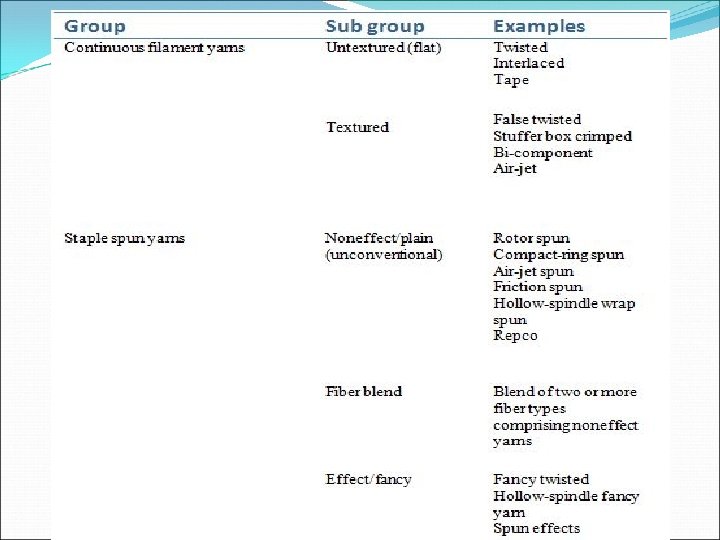
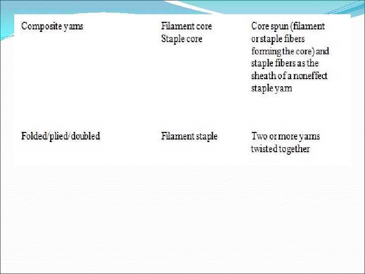
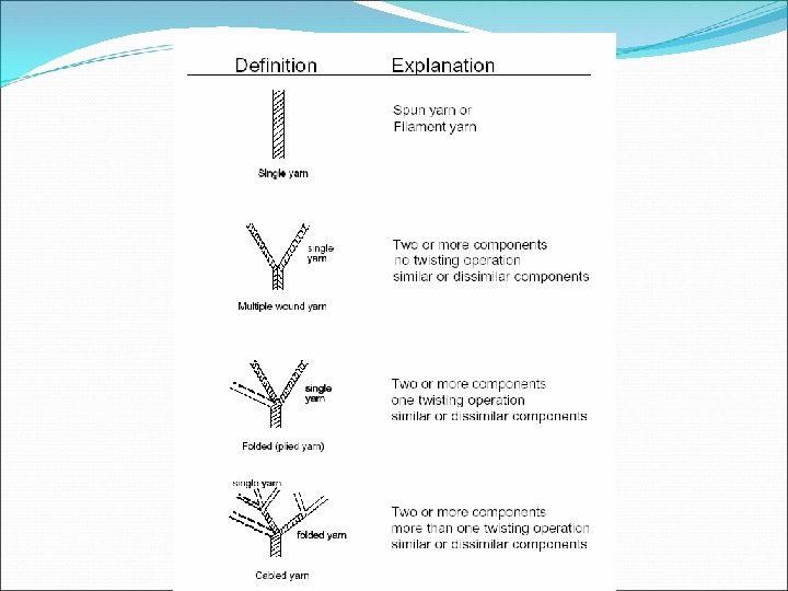
 Classification of spun yarn
 Spun yarn properties Yarn Count Twist Fibre parallelism
 How these properties affect the fabric
 Yarn Twist parameters § Direction of twist- S twist or Z twist § Twist angle – Angle of the twist § Twist level – Turns per unit length § Twist multiplier
 Relationship Tan α =π×d×t α- twist angle d- yarn diameter t – twist level By replacing “d’’s value with the density of the yarn we can get the twist multiplier – assuming the helix model of the yarn.
 Yarn Count § Direct count § Indirect count
 Fibre parallelism When twist is present in the yarn, the fiber parallelism is along the twist direction Will affect the yarn properties Dependant on the mechanical processes the fibres have to undergo prior to twist insertion
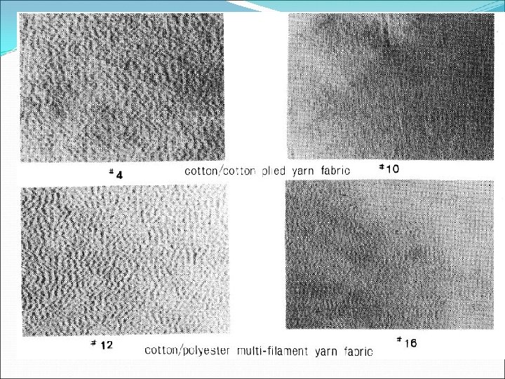
 Plied yarns and their effects on the fabric Plying two unbalanced yarns will provide a surface variation and a creates an effect on the surface of the fabric
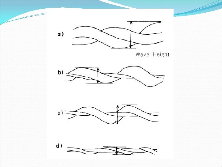
 Y axis – Wave height X axis – Count of thinner yarn Count of thicker yarn
 Carded ring spun yarns Blow room Carding Drawing Roving Spinning Winding
 How do the machines contribute to these yarn properties ?
 Developments in drafting
 Why Drafting is of importance drafting at Ring Frame is a major influence on yarn qualities & ultimately tells on even fabric appearance Therefore conversion of drafting is given a Drafting has the maximum influence on yarn quality high priority in the efforts to upgrade a Ring &ring performance. Frame and the payback from such Drafting in Ring Frame considerably influences not only evenness and appearance of yarn, but also investments is attractive. performance of yarn, appearance of fabric, and rejections due to yarn faults.
 Irregularity in Drafting Inadequate control over the movement of short and floating fibres. Slippage of strand fibres under the drafting roller. Variations in speed of drafting rollers. Mechanical faults.
 How the current drafting system developed Casablanca drafting Top arm drafting 1 st generation 2 nd generation
 Casablanca A 500 drafting represents the first development to improve the control over floating fibers. Middle roller Aprons
 Drawbacks of such system Back roller will have more slippages due to its weight Back roller has a bigger diameter, hence the back zone setting will be too long to accommodate short fibres Middle and front roller pressure is given by springs, which will deteriorate over time Plain bearings are used for top rollers, which need frequent lubrication. Which will attract fluff
 Top arm drafting represents a major break through in improving the quality and performance of drafting. Most of the problems that encountered with Casablanca drafting are overcome by Top arm drafting by adopting pendulum system of central arbour guidance. The top rollers are held at the middle of arbour by means of a saddle, which are weighted by heavy-duty springs.
 Advantages of the Top arm system Self-alignment of top roller in relation to bottom roller results on better grip over fibres. • Higher drafts are achievable because of better control over fibres. • About 1 -1. 5% units better U% and 15 -20% reduction in imperfections are obtained by conversion to top arm drafting. • Heavier weighting by the use of better grade springs reduces slippage.
 Offset drafting Improvements on Thick and Thin places
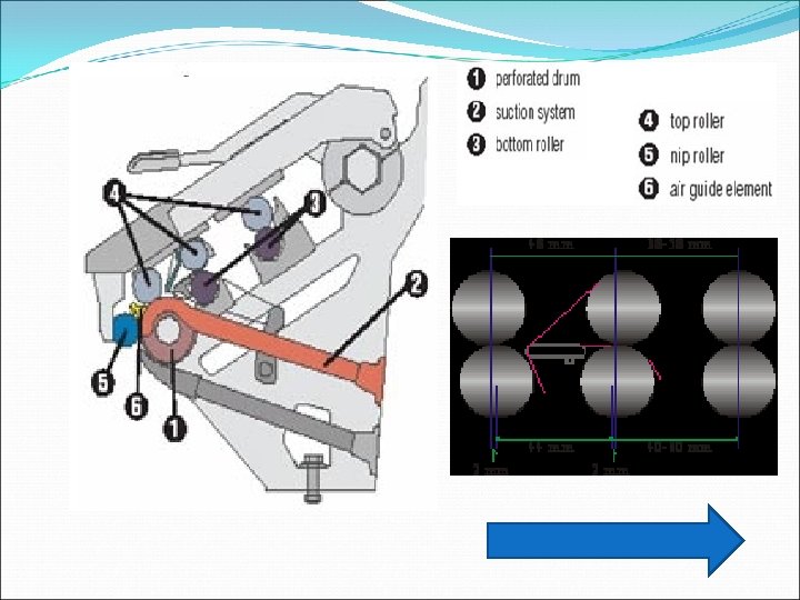
 Zinser system In ITV-Zinser system, illustrated in figure, condensing zone consists of a revolving perforated apron. The size of perforations in the apron is varied as per the count of the yarn to get the desired condensation
 Suction Perforated apron
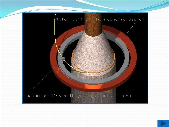
 Lakshmi’s development The Lakshmi Ro. Cos Compact System, works without air suction & uses magnetic mechanical compacting principle. Compacting yarn is produced by compacting the strand of fibres in the condensing zone to such an extent thereby avoiding spinning triangle and makes control over the strand of fibres. The contour & the path of the fibres enables all the fibres to align itself along with the axis of yarn more uniformly. SALIENT FEATURES: Magnetic compacting is more user friendly & avoids Air suction Air pipes Perforated drums or apron Additional air conditioning requirements
 Parts of a Traveller 1 - Inner traveller width 2 - Height of bow 3 - Yarn passage 4 - Wire section 5 - Traveller – ring contact surface 6 - Angle of toe 7 - Toe 8 - Opening 9 - Upper part of traveller bow 3 1 5 9 2 6 7 4 8 7
 Traveller classification Travellers are required to wind up yarns of different types of variations. This includes coarse/fine, smooth/hairy, strong/weak, natural/man made etc. Variances in traveler type to suit above changes of yarn type • Form • Mass • Finishing process • Wire profile • Size of yarn clearance
 Form of Traveller o. The traveller must be shaped to correspond exactly with the ring in the contact surface. o. The bow should be as flat as possible in order to keep centre of gravity low and improve smooth running. • low-bowed traveller reduced yarn clearance • low centre of gravity for fine cotton yarns for compact yarns • Optimum fibre lubrication • low to medium bowed • high-bowed traveller • small to medium yarn clearance for fine to medium fine cotton yarns • Normal fibre lubrication • large yarn clearance • for medium to coarse cotton yarns, also suitable for blends and synthetics • Reduced fibre lubrication
 Low-bowed traveller Vertical position High-bowed traveller Vertical position
 Traveller Friction Traveller has to regulate the spinning tension, this has to be high enough to keep the thread balloon stable but not too high. The fibres protruding from the yarn body between ring and traveller are crushed and form a steady regenerating lubrication film.
 Traveller friction 250 40 35. 5") m. N 350 300 Traveller weight (mg) Traveller friction 250 40 35. 5 200 31. 5 28 150 100 0. 08 0. 09 0. 11 Coefficient of friction (μ) 0. 12
m. N 350 300 Traveller weight (mg) Traveller friction 250 40 35. 5 200 31. 5 28 150 100 0. 08 0. 09 0. 11 Coefficient of friction (μ) 0. 12
 Wire sections This influence yarn quality, the running behavior and the life time of the traveller. • Used only for cotton • Improves the traveller lubrication Flat • For synthetics and blends. • Prevents fibre damage. Half round
 • For cotton and blends. • Through an enlarged contact surface on the ring raceway, highest performances are possible. • The mostly used wire section. udr - Ultra half round • For Core yarns with PES core, acrylics and delicate fibres. • f-profile at the toe increases the ring contact. • r-profile for fibre protection in the yarn passage. fr - Flat/round • Special profile for SU travellers. • Application for Viscose and Polyester. drh - Half round high
 Finishing Treatments Advantages of the additional finishes on travelers • Higher traveller speeds • Longer traveller life • Improved running behavior and as a result a more consistent yarn quality • Rust/oxidation protection (specially Starlet ) High performance travellers are only available with a finishing treatment
 A nickel coating is applied with") Finishing Treatments…. STARLET-Electrolytic surface treatment (special nickel plating) A nickel coating is applied with a special process. Low friction values in the yarn passage prevent fibre damages. Optimum resistance to corrosion.
Finishing Treatments…. STARLET-Electrolytic surface treatment (special nickel plating) A nickel coating is applied with a special process. Low friction values in the yarn passage prevent fibre damages. Optimum resistance to corrosion.
 Finishing Treatments…. PYRIT treated travellers have a enriched steel structure through additional components. The wear resistance is considerably increased. (Improves the running behaviour and guarantees a more consistent yarn quality. ) At high speeds the traveller service life can be increased by more than 100% compared to travellers with conventional finish
 FT Fw α FN Fz FR
 Ring/Traveller Systems
 is designed for spinning") Orbit Ring/Traveller System The Orbit ring/ traveller system (patented world-wide) is designed for spinning at top speeds whilst producing best yarn quality. The special features of the Orbit System are • Large contact area between traveller and the ring. This reduces the specific pressure. • Optimum heat dissipation traveller to the ring.
Orbit Ring/Traveller System The Orbit ring/ traveller system (patented world-wide) is designed for spinning at top speeds whilst producing best yarn quality. The special features of the Orbit System are • Large contact area between traveller and the ring. This reduces the specific pressure. • Optimum heat dissipation traveller to the ring.
 Advantages of the “Orbit System” • Increase in speed and production • High dynamic stability in traveller running • Reduction of yarn breakage • Improved and more consistent yarn quality • No thermal damage when processing synthetics Applications − Cotton combed − Polyester/cotton blends − Polyester 100% Yarn counts : Ne 30 to 60 recommended (finer and coarser both are possible)
 SU Ring/Traveller System The SU ring/ traveller system is suitable for the processing of synthetics (PAC, VC, PES) and their blends in the medium to coarse yarn count range. Design features of the SU system • Large contact area between ring and traveller reduces the specific pressure. • Optimum heat dissipation traveller to ring
 Advantages SU system • Better and more even yarn quality • Consistent yarn tension • No thermal fibre damages • Increased life cycle of travellers and rings • Higher spindle speeds • Lower yarn breakage rate • No yarn stain
 Magnetic Ring Spinning
 Magnetic Ring Spinning The factor which limits the production in ring spinning? ? ? Friction between the traveller and the ring Solution to overcome the limitation? ? ? A ring spinning system with a suspended ring which has a the ability of stabilizing the suspended ring with a high degree of precession. • Though there were systems of stabilizing the ring using air pressure and magnetic repulsion , existence of two systems make it difficult to complicated
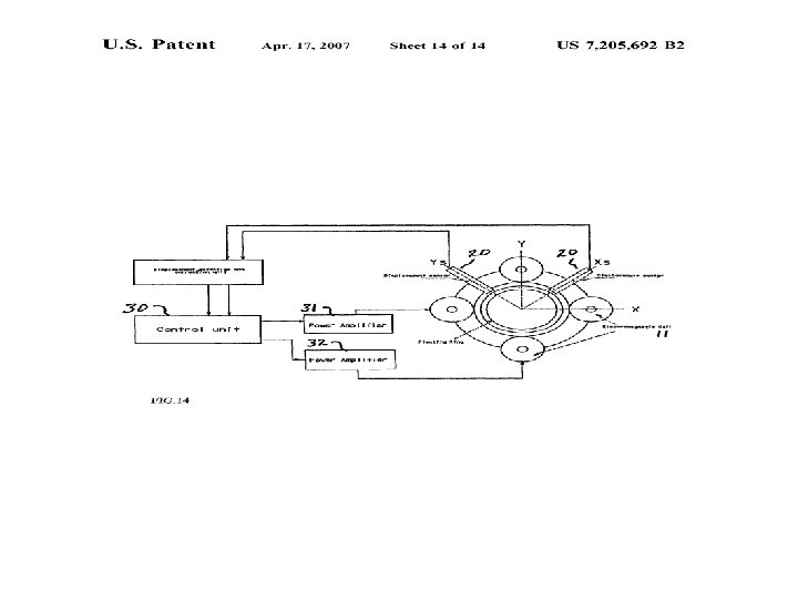
 The invention provides…… • Replacement of ring traveller configuration with only rotating, floating ring that has an eye on its inner middle surface. • The ring is kept suspended in space by magnetic levitation system which were in earlier developments. • The floating ring is rotated around its centre by the effect of winding of formed yarns over rotating spindle at the centre of the ring. • Sensors and feedback systems are used to control the magnetic fields and control the central position of the ring • The floating ring may be made out of any material but here they have used but preferably is made out of silicone steel material.
 Compact spinning Compact Spinning is simply the modification of conventional ring spinning system
![Compact Spinning systems are offered by: • REITER [COMFOURSPIN] • SUESSEN [ ELITE SPINNING](https://present5.com/presentation/17cce942a11666e557c04fcf0ed236e8/image-61.jpg "Compact Spinning systems are offered by: • REITER [COMFOURSPIN] • SUESSEN [ ELITE SPINNING") Compact Spinning systems are offered by: • REITER [COMFOURSPIN] • SUESSEN [ ELITE SPINNING SYSTEM ] • LAKSHMI [ Ro. Cos COMPACT SPINNING SYSTEM ] • ITV-ZINSER [ Comp. ACT 3 ]
Compact Spinning systems are offered by: • REITER [COMFOURSPIN] • SUESSEN [ ELITE SPINNING SYSTEM ] • LAKSHMI [ Ro. Cos COMPACT SPINNING SYSTEM ] • ITV-ZINSER [ Comp. ACT 3 ]
 Future of compact spinning Ring yarns which are spun on ring spinning frame without a spinning triangle, are unsurpassed in respect of their high strength and minimum hairiness
 Mechanism behind the compact spinning Drafting equipment of the Suessen Fiomax E 1 spinning machine Pair of delivery rollers , a double aprons area, a pair of front rollers and a condensing zone Drafting system of the Zinser AIR-COM -TEX 700 condenser ring spinning machine Standard three-cylinder drafting unit with two aprons and condensing unit
 Yarn Structure Comparison of Conventional Ring Spun Yarn & Compact Yarn
 Spinning triangle A long spinning triangle implies a long weak point more end breaks A short triangle represent a small weak point -fewer end breaks -if it is too short then the fibers on the edge must be strongly deflected to bind them in.
 Yarn characteristics Low hairiness Better strength & elongation -Higher production speeds Uniformity/less Irregularities (thick & thin places and neps)
 Technological advantages of compact yarns • Higher resistance to sloughing in winding process • Bobbin reduction • Cost savings at the weaving preparation stage due to decrease in sizing liquor • Uniform dyeing • Higher quality of the final product (good fibre utilization, increased lustre or a clearly enhanced colour contrast)
 Compact Spinning for Long Staple Yarns High tenacity and elongation - higher than the conventional ones but at the high twist level, the elongation values of compact and conventional ring yarns are very similar
 Hairiness Very low, even for yarns with low twist levels for all material types
 Thin places Statistically significant for only the fine yarn count
 Yarn tenacity Higher than the conventional but the difference of two systems changed according to the types of material
 Ctd. .
 Uster CV% values
 Carded cotton
 Combed Cotton
 Future of compact spinning Ring yarns which are spun on ring spinning frame without a spinning triangle, are unsurpassed in respect of their high strength and minimum hairiness
 Development of Twin Air-jet Nozzle System for Ring Spinning, to reduce hairiness
 Large scope of applications in air-jet Utility of the air- jet & ring combination, to reduce yarn hariness Still offer enough scope for further work Retaining of plus qualities of conventional rings spinning Combine the advantages of air-jet spinning system
 Importance of reducing hairiness Yarn hairiness can be a problem in down stream processes Unevenness of the yarn Cause problems in fabric production stage. High yarn breakages etc. . Appearance of yarns & ultimately in fabric appearance
 Design & Development of Twin Airjet Nozzle Two Nozzles ‘S’ nozzle air vortex with rotational direction opposite to that of mechanical twist (given by ring & traveller) ‘Z’ nozzle air vortex with rotational direction same as that of mechanical twist (given by ring & traveller)
 Two nozzles with same dimensions but different directions of jet orifices Two nozzles are housed in air jacket in tandem
 • Twin nozzle assembly is mounted in between the front roller nip & lappet hook in ring frame. (Without altering spg angle)
 Compressed air was administered inside both the nozzles through air jackets Yarn emerge from drafting zone, passes though the twin nozzle Subjected to the action of opposing swirling air current created by vortex inside the nozzle
 Trial conditions Spindle rpm – 14000 Roving hank – 0. 91 Yarn count – 19. 7 Tex(30 s’) - carded cotton Twist direction of yarn – Z
 Results of the trials Number of results was obtained on various properties of ring spun yarn with & without air jet nozzle system Tenacity Elongation Evenness Hairiness Yarn quality index etc. .
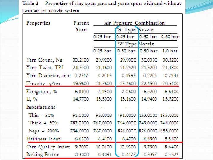
 Effect of twin Air-jet system on Tensile properties 0. 25 bar/0. 5 bar combination have resulted the highest increase in Tenacity Except 0. 5 bar/1. 0 bar combination, all others have a increase compared to yarn which was spun without jet arrangement.
 Fibre strand leaves from roller nips, subjected to air vortex inside ‘s’ nozzle. This vortex rotates the yarn opposite to yarn twist & moving opposite to the yarn flow direction. De-twist and loosen the structure. Then enters to the ‘Z’ nozzle. This rotates same direction to yarn twist & moving opposite to the yarn flow direction. Loosened structure undergoes in Re-twist & get tightened.
 Loosening & tightening up of the yarn structure results compaction of yarn. This contribute to increase in yarn strength.
 Effect of twin Air-jet system on Hairiness of yarn 0. 5 bar/1 bar combination gives the lowest hairiness Due to the sweeping & binding action of the air vortex at 1 bar in Z nozzle.
 Effect on other parameters Evenness – no significant variation. because evenness is mainly depend on drafting. Compaction – reduction of diameter, helps to increase the packing factor. Compaction of the yarn produced with jet system has contribute to the increase in tenacity.
 Reduction of hairiness & increase of tenacity, compactness is explained by Tucking of fibres in to the core of the yarn due to swirling air current which resulted in loosening & tightening of yarn structure.
 Automation in Ring Spinning
 In these slides… Following automation means used in Ring frame machine will be covered -Ring Rail movement -Motion to Drafting System -Automatic Doffing -Automatic Roving Transfer -Online Quality Control -Automatic Data Acquisition
 Ring Rail movement In conventional system achieved by a complex CAM lift system
 Ring Rail movement New system Lifted by a servo drive with screw lifting system Setting alteration by key pad data entry. Assembly time reduces enhancing manufacturing capacities.
 Motion to Drafting System In conventional system All gear driven Difficulty with setting alteration Needs to change gears when some parameters to be changed e: g: Draft, Twist
 New Automated Drafting System Electro draft System
 New Automated Drafting System Features of New system All rollers driven by individual motors, controlled by individual drives. Possible to alter draft and twist from the key pad. Fine tuning of twist & draft adjustments possible. Interfacing & drive communication through Profibusand other types of protocols makes controls simple and very accurate.
 Automatic Doffing Used to make the doffing function automated Has the main components -Doffing Beam Unit -Servo Disc Belt -ROBO DOFF unit
 Automatic Doffing How it Happens? -Full cops are gripped by the doffing unit and come down
 Automatic Doffing Full cops are placed on Servo disc belts & empty tubes are placed on spindles Servo disc Belt to transport cops
 Automatic Doffing The doffer transfers the full cops to the SERVO disc transport system, which conveys them either to the transfer station of the winder or to the fully automated ROBOload tube loader. The SERVO disc prevents tilting and thus ensure smooth transport, while the machine already resumes yarn production.
 Automatic Doffing- “Robo Doff” -Full packages are removed into a waiting container and empty tubes are fitted -Has a transfer capacity of up to 32 cops per minute.
 Automatic Roving Transfer Automatic Transfer of Roving Bobbins from Roving Frame to Ring Frame. • No deterioration in Roving quality due to storage and handling. • Better yarn quality.
 Online Quality Control Accurate recording of the spindle speed and realtime detection of yarn breakages. The stops are always assigned to the correct spindle automatically All sensors are connected to a PC-based central unit. All information concerning production, efficiency, ends down and slipping spindles is available on the display
 Each & every spindle is monitored and") Online Quality Control Individual Spindle Monitoring (ISM) Each & every spindle is monitored and controlled Sensor per each spindle and detects whether runs, slipper spindle or ends down spindle
Online Quality Control Individual Spindle Monitoring (ISM) Each & every spindle is monitored and controlled Sensor per each spindle and detects whether runs, slipper spindle or ends down spindle
 Online Quality Control
 Online Quality Control This sensor has a photo receiver facing a light emitting diode. During each revolution, the yarn balloon interrupts the light beam twice. The time between two successive interruptions serves as the basis for the calculation of the balloon speed, while the amount of light obstructed during the interruption is used as a rough diameter measure
 Online Quality Control All sensors on one machine are connected to the SCU(Sensor Control Unit). This unit offers a touch screen Windows-based user interface, USB interface and Ethernet connection which are used to monitor the progress of spinning
 Online Quality Control Display of Monitoring…
 Automatic Data Acquisition
 Automatic Data Acquisition All machines are connected to a Central computer. • Two way communication between the Computer and Machine can be established. • Possible to change the speed parameters from the Computer. • On line monitoring of the machine status. • Data acquired can be converted to production report.
 Machine Brake In conventional type, Brake is required on Ring Frame to prevent snarl formation while stopping the machine. • Conventional system uses electro magnetic or mechanical brakes. In new systems… • DC Injection brake from main inverter. • Optimum braking time by varying the parameters. • Elimination of all mechanical parts which require frequent resetting.
 Questions ? ? ?
 Thank you