

399567bf5847603ff62f1123f0a00447.ppt
- Количество слайдов: 88
 MX 62
MX 62
") MX 62 System SIL 3 Notified by EXAM n Full redundant system (SIL 3) N° BVS Pb 04/06 X n Up to 64 digital or analog transmitters n Up to 128 addressable relays n Up to 64 programmable analog outputs n MX 62 is not only a gas controller but a truly PLC dedicated to gas detection
MX 62 System SIL 3 Notified by EXAM n Full redundant system (SIL 3) N° BVS Pb 04/06 X n Up to 64 digital or analog transmitters n Up to 128 addressable relays n Up to 64 programmable analog outputs n MX 62 is not only a gas controller but a truly PLC dedicated to gas detection
 MX 62 System n n n The gas and flame control unit MX 62 enables: MX 62 to set up complex and elaborated installations. to increase the availability of the system: SIL 3 approved according to EN 50402 reduction of the material and wiring costs and of the whole equipment to ensure supervisions.
 Fonctionning safety gas detectionfixed systems of MX 62
 MX 62
MX 62
 Control units X 10 m Control unit X Schema 1 Schema 2 6 m 13 m without MX 62 20 m Estimated length for the wiring of the whole installation: 975 m 60 m 10 m 60 m Estimated length for the wiring of the whole installation: 466 m 13 m 40 m or a 1300 euros cost 12 m 15 m 30 m or a 620 euros cost 30 m 20 m Schema 2 bis Schema 1 bis MX 62 with MX 62 Estimated length for the wiring of the whole installation: 200 m Estimated length for the wiring of the whole installation: 151 m 60 m or a 200 euros cost or a 265 euros cost 30 m Legend: transm itter Control unit Looped Input Remote Module Cable: type U 1000 RVFV 8 F 70 per metre Delimitation of an industrial site Delimitation of high-risk zone under surveillance Network splitter
 MX 62 into detail n n n n n Power supplies control module Local or remote modules LED modules Display modules Relay modules Analog output modules Softwares and interfaces Housing.
 POWER SUPPLY BLOCK n The power supply block and its accessories (protections, switches, terminals) will be fixed in the housing 240 to 1500 W n The power supply block will depend on the choice of the equipment: 13 W maximum per channel
 Powers/protections/batteries: examples
: CM It is the control unit of the MX 62. Two") CONTROLLER MODULE (CPU): CM It is the control unit of the MX 62. Two synchronised 16 bits micro-controllers run in parallel. They redundantly and permanently compare measurements and status of transmitters to initiate all necessary alarms. The u. c. enables the connection to PC/PLC, different modules and MMC uploading.
CONTROLLER MODULE (CPU): CM It is the control unit of the MX 62. Two synchronised 16 bits micro-controllers run in parallel. They redundantly and permanently compare measurements and status of transmitters to initiate all necessary alarms. The u. c. enables the connection to PC/PLC, different modules and MMC uploading.
 Status of the controller : How does the MX 62 react in case of single fault. No fault SIL 2 or SIL 3 applications µC A inputs outputs µC B System in normal operation. WARNING !!! The info received and exchanged between both processors are different µC A inputs outputs µC B LOSS of one SIL LEVEL but the system is still safe.
 CONTROLLER MODULE « CM » : connections »
 controller A With remote modules: LPM Flat") MX 62 and transmitters ( max 64) controller A With remote modules: LPM Flat cables CPU (controller module) With local modules: AIM controller B Flat cables or twisted wires
MX 62 and transmitters ( max 64) controller A With remote modules: LPM Flat cables CPU (controller module) With local modules: AIM controller B Flat cables or twisted wires
 MX 62 can be connected with : all types of transmitters 4. . 20 m. A ( 2 or 3 wires ) digital addressable transmitters via a safety MODBUS ASCII communication Wheatstone bridge detectors via an
 8 addressable modules AIM fitted with 8 inputs Analog input module transmitters 4. . 20 m. A + RS 485 (service) Module I Analog input module transmitters 4. . 20 m. A controller A + RS 485 (service) Module II : : : Analog input module transmitters 4. . 20 m. A Module VIII 0, 5 m controller B + RS 485 (service)
 Analog Input Modules: connections 24 v = transmitter power suppl GND = ground Sig. = signal 4 -20 m. A from the transmitter A = line A of RS 485 network B = line B of RS 485 network
 (loop/4 to 20 m. A)") Analog Input Modules AIM Transmitter ( 3 wires ) (loop/4 to 20 m. A) (power supply + signal) Site Transmitter ( 2 wires )
Analog Input Modules AIM Transmitter ( 3 wires ) (loop/4 to 20 m. A) (power supply + signal) Site Transmitter ( 2 wires )
 And 2 additional wires for RS") Site 3 - wires (power supply + signal) And 2 additional wires for RS 485 Remote Transmitter programming/calibration
Site 3 - wires (power supply + signal) And 2 additional wires for RS 485 Remote Transmitter programming/calibration
 « CATALYTIC DETECTOR/ 4 -20 m. A » ADAPTER MODULE WB interface (filaments / 4 -20 m. A) 4. . 20 m. A analog. catalytic detector Module VIII 4. . 20 m. A analog. + RS 485 (service) controller A controller B
 WB INTERFACES in housing
 Analog Input Modules 4 -20 m. A CPU Flat cable 8 wires nota: the connected module with one transmitter is considered by the control unit to be fitted with 8 transmitters. Maximal configuration: 8 analog input modules (8 transmitters max. . per module) 64 transmitters in total Back housing of a control unit MX 62
 Analog input modules: location and connections
 AIM: special version Smoke detector +2 VCC +24 V GND m. A A B RFL m. A Curent limitor module (20 m. A) maximum 32 detectors
 Adapter Module LPM for digital and analog transmitters Adapter module For numeric or/and Analog transmitters connections controller A : Adapter module For numeric or/and Analog transmittes connections 1, 6 km max - up to 4 remote/addressable modules controller B (16 addresses per loop) - adress module : 1/3/5/7
 Section 2 loop Section 1 ex: 16 adresses, lenght of loop=1. 2 Kms* < 1. 2 Kms * with tox. capt Ø 380 m or 6 up to 24 ha power supply+network -(2 x 0, 75 mm²)+1 p 0. 32 mm²-
 AEM adapter module < 1. 2 Kms Mx") ( 5 wires per captor ) AEM adapter module < 1. 2 Kms Mx 62 Local power alim supply locale
( 5 wires per captor ) AEM adapter module < 1. 2 Kms Mx 62 Local power alim supply locale
 The ADAPTER MODULES Controlroom where the MX is: 62 Capteur note: the connected module with one transmitter is considered by the control unit to be fitted with 8 transmitters. 2 CPU 3 1 Back housing of a control unit MX 62 Building A tion ec onn rt c Sho 4 Building B Maximal configuration: 4 adapter modules 64 transmitters
 DISPLAY and LED modules
 LED MODULES : LEDM A group of 8 LED front panel per card. 16 channels front panels (3 U-1/2 19 in)
 Channel LED front panel Over scale alarme 3 alarme 2 Alarms are entirely and alarme 1 Under scale (too negative) independently programmable Failure ON/OFF Manual proper measurement displayed on LCD panel module and alarm reset
 «LED» front panels LED front panels can be remote controller A controller B from the CPU.
 «LED» cards: connections
 «LED» modules: location and connections
 LCD modules
 LCDM Module Escape key up key Clear messages down key validation key Service informations
 LCD Module n n n n The display clearly indicates: the measurements and the units the kind of gas and the scale of measurement the alarms the identification of the visual transmitter the information for maintenance Allows the printing gestion etc. . .
 LCD Module n n n The display can be programmed differently: no display cyclic display of the channels display on channel where an alarm is triggered cyclic display on channels where alarms are triggered manual display
 4 LED for service informations : n System failure: system completely out of order n Single mode: redundancy is disrupted n Service: maintenance positions currently used n Battery: power cuts but saved by batteries…
 LCD module: LCDM n In option memorizes data and events that can be saved on PC thanks to the use of a communication module (2 X RS 485) fitted with a memory 16 Mb = capacity of 5 days n fitted with a memory 256 Mb = capacity of 3 months n n The « histogram » function(FIFO mode) is saved by a lithium battery.
 Local and Remote LCD Modules LOCAL n n n Remote without LED without indications Oldham ’s logo indication of measurement under alarm condition
 LCD module: installations n The display module can be directly fixed in the housing… … or remote from the housing thanks to a network RS 485: 30 *LCD modules max. n Important: the first display module will be the master and others will be slaves (keypad deactivated). n n Note: without remote LED modules. . .
 LCD module: connections
 LCD module : location and connections
 LCD, LED panels system’srepresentation. 600 mm 800 mm 2 m Distant zone n° 2 Example: control room unit n° 2 Distant zone n° 1 Example: control room ofthe unit n° 1
 MX 62
MX 62
 REMOTE RELAY MODULES: RM 1 km controller A RS 485 Remote and addressable relay module : Remote and addressable relay module 8 modules MAX. controller B
 RELAY MODULE RM n A relay module can be fitted with 1 or 2 cards: n a basic relay module RBM fitted with 8 relays and can be extended. . . n … a 2 nd extension card other relays. n REM fitted with 8 Adress 1 to 8 for each module (rotative switch)
 Relay Module: RM n with 8 modules fitted with 16 relays: up to 128 addressable relays can be used n Independent and programmable relays can be piloted by FUNCTIONS defined by the user: alarm type, acknowledgement mode, failures, logics states etc….
 Relay module : connections
 Relay module : location and connections
 The local or remote relay module Control room where the MX 62 is: Room 1 Room 2 Building A Relay nota: the linked module is considered by the control unit to be fitted with 8 or 16 relays CPU 8 channels instandard 8 channels in standard + 8 channels in option Back housingof a control unit MX 62 Room 3 Building B Room 4
 Remote analog Output Modules: AAM 1 km controller A RS 485 Remote and addressable Analog output module : Remote and addressable Analog output module 8 modules MAX. controller B
 Analog Output Modules: AAM 8 modules fitted with 8 outputs, up to 64 outputs can be used ! n a common output can be linked with several transmitters n PROGRAMMABLE outputs can be activated by FUNCTIONS defined by the user: averaged measurements, MIN/MAX, instantaneous measurements, sources etc…. n
 - long. Max") Analog Output Modules: connections 1. 3 Module Contrôleur ( CM ) - long. Max 2 m 5. 1 Module Sorties Analogiques ( AAM ) - long. Max 0, 5 m 4. 2 Module Relais ( RM ) - long. Max 0, 5 m Limande ( 16 fils ) Cavalier Fin de Bus Adresses de 1 à 8 1. 7 Module Contrôleur ( CM ) 4. 3 Module Relais ( RM ) 2 3 1 AAM- µC 1 1 A 2 B 2 + Gauche à FIN DE BUS Droite à AUTRES MODULES AAM- 5. 5 A 1 B 1 + 1. 6 Module Contrôleur ( CM ) 4. 4 Module Relais ( RM ) Sélecteur rotatif µC 2 4 5 6 7 5. 1 1 + +24 V GND Module Sorties Analogiques ( AAM ) 5. 3 Long. Max 0, 5 m 8 5. 3 5. 4 2 2 - 3 4 5 + + - - - 6 - 7 8 + + + - - Sorties analogiques Sélection du type de signal Position du cavalier Gauche Droite à 0 – 10 V à 4– 20 m. A - Limande ( 16 fils )
Analog Output Modules: connections 1. 3 Module Contrôleur ( CM ) - long. Max 2 m 5. 1 Module Sorties Analogiques ( AAM ) - long. Max 0, 5 m 4. 2 Module Relais ( RM ) - long. Max 0, 5 m Limande ( 16 fils ) Cavalier Fin de Bus Adresses de 1 à 8 1. 7 Module Contrôleur ( CM ) 4. 3 Module Relais ( RM ) 2 3 1 AAM- µC 1 1 A 2 B 2 + Gauche à FIN DE BUS Droite à AUTRES MODULES AAM- 5. 5 A 1 B 1 + 1. 6 Module Contrôleur ( CM ) 4. 4 Module Relais ( RM ) Sélecteur rotatif µC 2 4 5 6 7 5. 1 1 + +24 V GND Module Sorties Analogiques ( AAM ) 5. 3 Long. Max 0, 5 m 8 5. 3 5. 4 2 2 - 3 4 5 + + - - - 6 - 7 8 + + + - - Sorties analogiques Sélection du type de signal Position du cavalier Gauche Droite à 0 – 10 V à 4– 20 m. A - Limande ( 16 fils )
 Analog Output Modules: connections
 The addressableanalog output module Room 1 Control room where the MX 62 is: Building A CPU Back housing of a control unit MX 62 Room 3 Room 2 Building C note: the connected module with one output is considered by the control unit to be fitted with 8 outputs. Building B
 MX 62
MX 62
 MX 62: softwares n CONFIGPRO n Alarm monitoring n VISUAL-62 n On demand …
 The redundant module to a monitor The non redundant module to monitor the alarms Modbus communication module (redundant ) Secured monitor Visual 62 Config. Pro Visual 62 Communication module PROFIBUS DP Back housing ofa control unit MX 62 Alarms monitoring
: connectors I/O RS 232 CPU linking RS 232 outputs") SPS module (serial priotity switch): connectors I/O RS 232 CPU linking RS 232 outputs (reading only, with auxiliary masters) SERVICE RS 232 output (configpro) , reading and writting with auxiliary master.
SPS module (serial priotity switch): connectors I/O RS 232 CPU linking RS 232 outputs (reading only, with auxiliary masters) SERVICE RS 232 output (configpro) , reading and writting with auxiliary master.
 CM MODULE MPM MODULE Visual 62 WINPRO Visual 62
 Visual-62 Supervision of MX 62
") Principle Remote supervision software for MX-62 (maximum 16 units per supervision network)
Principle Remote supervision software for MX-62 (maximum 16 units per supervision network)
 Functions - Visualization of instantaneous data Synoptics of customers Histograms Curves printing alarm and event gestion. . .
 Example of architecture Visual 62 Others on demande Visual 62
 A ligne for a control unit Sélection of number of units") Configuration visualization (Administrator) A ligne for a control unit Sélection of number of units linked Protocole of communication programming Port programming Configuration menu (RS or ETHERNET) Adress of control unit Name of control unit Informations of the user ’ PC Zone of alarms informations
Configuration visualization (Administrator) A ligne for a control unit Sélection of number of units linked Protocole of communication programming Port programming Configuration menu (RS or ETHERNET) Adress of control unit Name of control unit Informations of the user ’ PC Zone of alarms informations
 Example of site This window is piloted by the user : graphic visualization of the captor. MENU Vue of captor Zone of alarms
 detector information window To display the whole informations from a detector and communication state to the MX-62.
 control unit vues
 Curves Real time curves or « histograms » To active the different curves
 Histograms measurements, events and alarms and printing possibilities
 MX 62: INTERFACES n « Centronics » ASCII Interface for printer connection: a 128 Kb capacity, stores the events and restores them as soon as the parallel printer is connected n PROFIBUS DP Interface (ETHERNET, TCP/IP in option): redundant communication port n Remote access for maintenance via a MODEM.
 auxiliary module « MIMIC »
 MIMIC MODULE « wrapping » outputs: 56 opened collectors Flat cable: copied LED panel copy LED +24 Vcc (M/A DEF UDS AL 1 AL 2 AL 3 OVS) Collecteurs v 8 +24 Vcc Collecteurs v 7 +24 Vcc Collecteurs v 6 +24 Vcc Collecteurs v 5 +24 Vcc Collecteurs v 4 +24 Vcc Collecteurs v 3 +24 Vcc Collecteurs v 2 +24 Vcc Collecteurs v 1 . . . . . . . Power + RS 485 + Bus OUT Bus IN 10 ohms B A Test Reset Flat cable: LED/LCD bus . . . . . . . Power + RS 485 + B A Test Reset Bus OUT Bus IN 40 mm 71 mm ou 12 TE 128 mm ou 3 U
 MIMIC MODULE ADRESSE of LED copy Mode test Adresse Ouvert Fin de ligne 14 mm 162 mm Rs 485
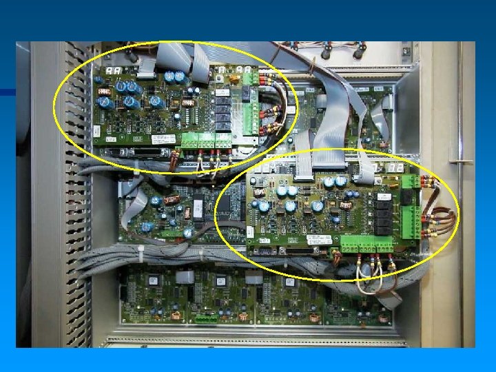
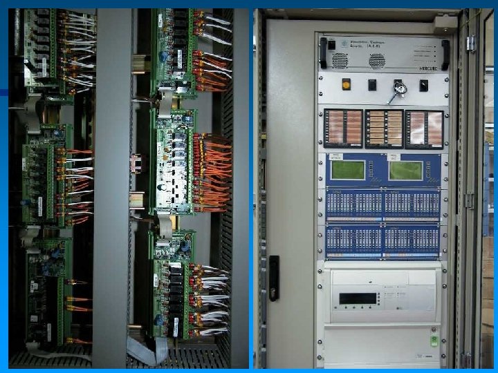
 Modules / rack
 ON DEMAND… GAS STORAGE
 MX 62
MX 62
 HOUSING …Of course the MX 62 suits customer need and free space allocated to them. Availability: - 19’’ Rack for equipment in industrial cabinet, floor or wall-mounted housing. - Panels for equipment of small and large electrician enclosure.
 H S U O G IN
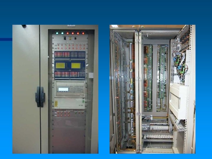
 Examples of orders
 Housing: other examples
 Wiring: examples on demand. . . :
 Wall mounting cabinets
 A flammeproof local display