

534f8d1b0aa09002763a96b6ecb0f67e.ppt
- Количество слайдов: 93
 Modern GPU Architecture CSE 694 G Game Design and Project Prof. Roger Crawfis
 GPU vs CPU l l l A GPU is tailored for highly parallel operation while a CPU executes programs serially For this reason, GPUs have many parallel execution units and higher transistor counts, while CPUs have few execution units and higher clockspeeds A GPU is for the most part deterministic in its operation (though this is quickly changing) GPUs have much deeper pipelines (several thousand stages vs 10 -20 for CPUs) GPUs have significantly faster and more advanced memory interfaces as they need to shift around a lot more data than CPUs
 The GPU pipeline l The GPU receives geometry information from the CPU as an input and provides a picture as an output l Let’s see how that happens host interface vertex processing triangle setup pixel processing memory interface
 Host Interface The host interface is the communication bridge between the CPU and the GPU l It receives commands from the CPU and also pulls geometry information from system memory l It outputs a stream of vertices in object space with all their associated information (normals, texture coordinates, per vertex color etc) l host interface vertex processing triangle setup pixel processing memory interface
 Vertex Processing The vertex processing stage receives vertices from the host interface in object space and outputs them in screen space l This may be a simple linear transformation, or a complex operation involving morphing effects l Normals, texcoords etc are also transformed l No new vertices are created in this stage, and no vertices are discarded (input/output has 1: 1 mapping) l host interface vertex processing triangle setup pixel processing memory interface
 Triangle setup In this stage geometry information becomes raster information (screen space geometry is the input, pixels are the output) l Prior to rasterization, triangles that are backfacing or are located outside the viewing frustrum are rejected l Some GPUs also do some hidden surface removal at this stage l host interface vertex processing triangle setup pixel processing memory interface
 l A fragment is generated if and only if its center") Triangle Setup (cont) l A fragment is generated if and only if its center is inside the triangle l Every fragment generated has its attributes computed to be the perspective correct interpolation of the three vertices that make up the triangle host interface vertex processing triangle setup pixel processing memory interface
Triangle Setup (cont) l A fragment is generated if and only if its center is inside the triangle l Every fragment generated has its attributes computed to be the perspective correct interpolation of the three vertices that make up the triangle host interface vertex processing triangle setup pixel processing memory interface
 Fragment Processing Each fragment provided by triangle setup is fed into fragment processing as a set of attributes (position, normal, texcoord etc), which are used to compute the final color for this pixel l The computations taking place here include texture mapping and math operations l Typically the bottleneck in modern applications l host interface vertex processing triangle setup pixel processing memory interface
 Memory Interface Fragment colors provided by the previous stage are written to the framebuffer l Used to be the biggest bottleneck before fragment processing took over l Before the final write occurs, some fragments are rejected by the zbuffer, stencil and alpha tests l On modern GPUs, z and color are compressed to reduce framebuffer bandwidth (but not size) l host interface vertex processing triangle setup pixel processing memory interface
 Programmability in the GPU Vertex and fragment processing, and now triangle setup, are programmable l The programmer can write programs that are executed for every vertex as well as for every fragment l This allows fully customizable geometry and shading effects that go well beyond the generic look and feel of older 3 D applications l host interface vertex processing triangle setup pixel processing memory interface
 Diagram of a modern GPU Input from CPU Host interface Vertex processing Triangle setup Pixel processing Memory Interface 64 bits to memory
 CPU/GPU interaction The CPU and GPU inside the PC work in parallel with each other l There are two “threads” going on, one for the CPU and one for the GPU, which communicate through a command buffer: l GPU reads commands from here Pending GPU commands CPU writes commands here
 If this command buffer is drained empty, we are CPU limited") CPU/GPU interaction (cont) If this command buffer is drained empty, we are CPU limited and the GPU will spin around waiting for new input. All the GPU power in the universe isn’t going to make your application faster! l If the command buffer fills up, the CPU will spin around waiting for the GPU to consume it, and we are effectively GPU limited l
CPU/GPU interaction (cont) If this command buffer is drained empty, we are CPU limited and the GPU will spin around waiting for new input. All the GPU power in the universe isn’t going to make your application faster! l If the command buffer fills up, the CPU will spin around waiting for the GPU to consume it, and we are effectively GPU limited l
 Another important point to consider is that programs that use the") CPU/GPU interaction (cont) Another important point to consider is that programs that use the GPU do not follow the traditional sequential execution model l In the CPU program below, the object is not drawn after statement A and before statement B: l • Statement A • API call to draw object • Statement B l Instead, all the API call does, is to add the command to draw the object to the GPU command buffer
CPU/GPU interaction (cont) Another important point to consider is that programs that use the GPU do not follow the traditional sequential execution model l In the CPU program below, the object is not drawn after statement A and before statement B: l • Statement A • API call to draw object • Statement B l Instead, all the API call does, is to add the command to draw the object to the GPU command buffer
 Synchronization issues This leads to a number of synchronization considerations l In the figure below, the CPU must not overwrite the data in the “yellow” block until the GPU is done with the “black” command, which references that data: l GPU reads commands from here CPU writes commands here data
 Modern APIs implement semaphore style operations to keep this from causing") Syncronization issues (cont) Modern APIs implement semaphore style operations to keep this from causing problems l If the CPU attempts to modify a piece of data that is being referenced by a pending GPU command, it will have to spin around waiting, until the GPU is finished with that command l While this ensures correct operation it is not good for performance since there a million other things we’d rather do with the CPU instead of spinning l The GPU will also drain a big part of the command buffer thereby reducing its ability to run in parallel with the CPU l
Syncronization issues (cont) Modern APIs implement semaphore style operations to keep this from causing problems l If the CPU attempts to modify a piece of data that is being referenced by a pending GPU command, it will have to spin around waiting, until the GPU is finished with that command l While this ensures correct operation it is not good for performance since there a million other things we’d rather do with the CPU instead of spinning l The GPU will also drain a big part of the command buffer thereby reducing its ability to run in parallel with the CPU l
 Inlining data l One way to avoid these problems is to inline all data to the command buffer and avoid references to separate data: GPU reads commands from here data CPU writes commands here l However, this is also bad for performance, since we may need to copy several Mbytes of data instead of merely passing around a pointer
 Renaming data A better solution is to allocate a new data block and initialize that one instead, the old block will be deleted once the GPU is done with it l Modern APIs do this automatically, provided you initialize the entire block (if you only change a part of the block, renaming cannot occur) l data Better yet, allocate all your data at startup and don’t change them for the duration of execution (not always possible, however)
 GPU readbacks l The output of a GPU is a rendered image on the screen, what will happen if the CPU tries to read it? GPU reads commands from here Pending GPU commands CPU writes commands here l The GPU must be syncronized with the CPU, ie it must drain its entire command buffer, and the CPU must wait while this happens
 We lose all parallelism, since first the CPU waits for the") GPU readbacks (cont) We lose all parallelism, since first the CPU waits for the GPU, then the GPU waits for the CPU (because the command buffer has been drained) l Both CPU and GPU performance take a nosedive l l Bottom line: the image the GPU produces is for your eyes, not for the CPU (treat the CPU -> GPU highway as a one way street)
GPU readbacks (cont) We lose all parallelism, since first the CPU waits for the GPU, then the GPU waits for the CPU (because the command buffer has been drained) l Both CPU and GPU performance take a nosedive l l Bottom line: the image the GPU produces is for your eyes, not for the CPU (treat the CPU -> GPU highway as a one way street)
 Some more GPU tips Since the GPU is highly parallel and deeply pipelined, try to dispatch large batches with each drawing call l Sending just one triangle at a time will not occupy all of the GPU’s several vertex/pixel processors, nor will it fill its deep pipelines l Since all GPUs today use the zbuffer algorithm to do hidden surface removal, rendering objects front-toback is faster than back-to-front (painters algorithm), or random ordering l Of course, there is no point in front-to-back sorting if you are already CPU limited l
 Graphics Hardware Abstraction l Open. GL and Direct. X provide an abstraction of the hardware.
 Trend from pipeline to data parallelism Coord, normal Transform Coordinate Transform Lighting Command Processor Clip testing 6 -plane Clipping state Frustum Clipping Divide by w (clipping) Viewport Divide by w Prim. Assy. Viewport Clark “Geometry Engine” CS 248 Lecture 14 (1983) Round-robin Aggregation Backface cull SGI 4 D/GTX (1988) SGI Reality. Engine Kurt Akeley, Fall 2007 (1992)
 is provided between task stages n n Accommodates variation") Queueing FIFO buffering (first-in, first-out) is provided between task stages n n Accommodates variation in execution time Provides elasticity to allow unified load balancing to work FIFOs can also be unified n n Share a single large memory with multiple head-tail pairs Application Vertex assembly FIFO Vertex operations FIFO Primitive assembly Allocate as required FIFO CS 248 Lecture 14 Kurt Akeley, Fall 2007
Queueing FIFO buffering (first-in, first-out) is provided between task stages n n Accommodates variation in execution time Provides elasticity to allow unified load balancing to work FIFOs can also be unified n n Share a single large memory with multiple head-tail pairs Application Vertex assembly FIFO Vertex operations FIFO Primitive assembly Allocate as required FIFO CS 248 Lecture 14 Kurt Akeley, Fall 2007
 Data locality Prior to texture mapping: Application n Vertex pipeline was a stream processor Vertex assembly n Each work element (vertex, primitive, fragment) carried all the state it needed Vertex operations Modal state was local to the pipeline stage Primitive assembly n n n Assembly stages operated on adjacent work elements Data locality was inherent in this model Post texture mapping: n All application-programmable stages have memory access (and use them) n n Primitive operations So the vertex pipeline is no longer a stream processor Data locality must be fought for … CS 248 Lecture 14 Rasterization Fragment operations Framebuffer Display Kurt Akeley, Fall 2007
 Modern memory (DRAM) operates in large blocks n Memory") Post-texture mapping data locality (simplified) Modern memory (DRAM) operates in large blocks n Memory is a 2 -D array n Access is to an entire row To make efficient use of memory bandwidth all the data in a block must be used Two things can be done: n Aggregate read and write requests n n n Memory controller and cache Complex part of GPU design Organize memory contents coherently (blocking) CS 248 Lecture 14 Kurt Akeley, Fall 2007
Post-texture mapping data locality (simplified) Modern memory (DRAM) operates in large blocks n Memory is a 2 -D array n Access is to an entire row To make efficient use of memory bandwidth all the data in a block must be used Two things can be done: n Aggregate read and write requests n n n Memory controller and cache Complex part of GPU design Organize memory contents coherently (blocking) CS 248 Lecture 14 Kurt Akeley, Fall 2007
 The n. Vidia G 80 GPU ► ► ► 128 streaming floating point processors @1. 5 Ghz 1. 5 Gb Shared RAM with 86 Gb/s bandwidth 500 Gflop on one chip (single precision)
 Why are GPU’s so fast? l Entertainment Industry has driven the economy of these chips? l Males age 15 -35 buy $10 B in video games / year l Moore’s Law ++ l Simplified design (stream processing) l Single-chip designs.
 Modern GPU has more ALU’s
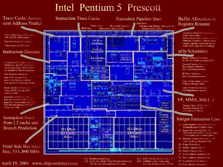
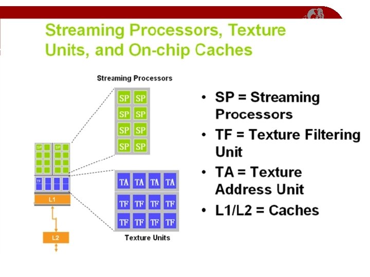
 n. Vidia G 80 GPU Architecture Overview • 16 Multiprocessors Blocks • Each MP Block Has: • 8 Streaming Processors (IEEE 754 spfp compliant) • 16 K Shared Memory • 64 K Constant Cache • 8 K Texture Cache • Each processor can access all of the memory at 86 Gb/s, but with different latencies: • Shared – 2 cycle latency • Device – 300 cycle latency
 A Specialized Processor l Very Efficient For l l Fast Parallel Floating Point Processing Single Instruction Multiple Data Operations High Computation per Memory Access Not As Efficient For l l Double Precision Logical Operations on Integer Data Branching-Intensive Operations Random Access, Memory-Intensive Operations
 Application Data Assembler Vtx Thread Issue Vertex assembly") Implementation = abstraction (from lecture 2) Application Data Assembler Vtx Thread Issue Vertex assembly Setup / Rstr / ZCull Prim Thread Issue Frag Thread Issue SP SP TF L 1 SP SP SP L 2 FB Source : NVIDIA SP SP TF L 1 L 2 FB NVIDIA Ge. Force 8800 CS 248 Lecture 14 SP TF L 1 L 2 FB SP TF TF L 1 L 2 FB SP Thread Processor Vertex operations Primitive operations Rasterization L 2 FB Primitive assembly Fragment operations Framebuffer Open. GL Pipeline Kurt Akeley, Fall 2007
Implementation = abstraction (from lecture 2) Application Data Assembler Vtx Thread Issue Vertex assembly Setup / Rstr / ZCull Prim Thread Issue Frag Thread Issue SP SP TF L 1 SP SP SP L 2 FB Source : NVIDIA SP SP TF L 1 L 2 FB NVIDIA Ge. Force 8800 CS 248 Lecture 14 SP TF L 1 L 2 FB SP TF TF L 1 L 2 FB SP Thread Processor Vertex operations Primitive operations Rasterization L 2 FB Primitive assembly Fragment operations Framebuffer Open. GL Pipeline Kurt Akeley, Fall 2007
 Applicationprogrammable parallel processor Fixed-function assembly processors Application Data Assembler this was") Correspondence (by color) Applicationprogrammable parallel processor Fixed-function assembly processors Application Data Assembler this was missing Vtx Thread Issue Prim Thread Issue Vertex assembly Setup / Rstr / ZCull Frag Thread Issue SP SP TF L 1 SP SP TF L 2 FB SP SP TF L 1 FB Primitive assembly Primitive operations Rasterization (fragment assembly) L 2 NVIDIA Ge. Force 8800 CS 248 Lecture 14 SP Fixed-function L 1 framebuffer operations L 1 L 2 FB SP TF TF L 1 L 2 FB SP Thread Processor Vertex operations L 2 FB Fragment operations Framebuffer Open. GL Pipeline Kurt Akeley, Fall 2007
Correspondence (by color) Applicationprogrammable parallel processor Fixed-function assembly processors Application Data Assembler this was missing Vtx Thread Issue Prim Thread Issue Vertex assembly Setup / Rstr / ZCull Frag Thread Issue SP SP TF L 1 SP SP TF L 2 FB SP SP TF L 1 FB Primitive assembly Primitive operations Rasterization (fragment assembly) L 2 NVIDIA Ge. Force 8800 CS 248 Lecture 14 SP Fixed-function L 1 framebuffer operations L 1 L 2 FB SP TF TF L 1 L 2 FB SP Thread Processor Vertex operations L 2 FB Fragment operations Framebuffer Open. GL Pipeline Kurt Akeley, Fall 2007
 Texture Blocking 6 D Organization Cache Size 4 x 4 blocks Cache Line Size 4 x 4 texels (s 1, t 1) (s 2, t 2) (s 3, t 3) Address CS 248 Lecture 14 base s 1 t 1 Source: Pat Hanrahan s 2 t 2 s 3 t 3 Kurt Akeley, Fall 2007
 Direct 3 D 10 System and NVIDIA Ge. Force 8800 GPU
 Overview n n Before graphics-programming APIs were introduced, 3 D applications issued their commands directly to the graphics hardware n Fast n Became infeasible with increasing graphics hardware Graphics APIs like Direct. X and Open. GL act as a middle layer between the application and the graphics hardware Using this model, applications write one set of code and the API does the job of translating this code to instructions that can be understood by the underlying hardware A product of detailed collaboration among n Application developers n Hardware designers n API/runtime architects
 Problems with Earlier Versions n High state-change overhead n n n Excessive variation in hardware accelerator capabilities Frequent CPU and GPU synchronization n n Generating new vertex data or building a cube map requires more communication, reducing efficiency Instruction type and data type limitations n n n Changing state (in terms of vertex formats, textures, shader parameters, blending modes etc. ) incurs a high overhead Neither vertex nor pixel shader supports integer instructions Pixel shader accuracy for FP arithmetic can be improved Resource Limitations n n The resources sizes were modest Algorithms had to be scaled back or broken into several passes
 Main Features of Direct. X 10 Main objective is to reduce CPU overhead Some of the key changes are: n n n Faster and cleaner runtime n n Programmable pipeline is directed using a low-level abstraction layer called Runtime. It hides the differences between varying applications and provides device-independent resource management The runtime of Direct. X 10 has been redesigned to work more closely with the graphics hardware The Ge. Force 8800 architecture has been designed keeping in mind the changes in Runtime Treatment of validation enhances performance
 Main Features of Direct. X 10 n New Data Structure for Texture n n n n Switching between multiple textures causes high state-change cost Direct. X 9 used to use texture atlas : but the approach was limited to 4096 x 4096 and resulted in incorrect filtering at texture boundaries Direct. X 10 uses texture array : up to 512 textures can be stored sequentially Texture resolution extended to 8192 x 8192 Maximum number of textures a shader can use is 128 (was 16) The instructions handling this array are executed by GPU Predicted Draw n n Complex objects are first drawn using a simple box approximation. If drawing the box has no effect on the final image, the complex object is not drawn at all. This is also known as an occlusion query With Direct. X 10, this process is done entirely on the GPU, eliminating all CPU intervention
 Main Features of Direct. X 10 n Stream Out n The vertex or geometry shader can output their results directly into graphics memory, bypassing the pixel shader n Result can be iteratively processed in the GPU only n State Object n State management must be done in low cost n Huge range of states in Direct. X 9 is consolidated into 5 state objects: Input. Layout, Sampler, Rasterizer, Depth. Stencil, Blend n State changes that previously required multiple commands now need a single call
 Main Features of Direct. X 10 n Constant Buffers n n n Constants are pre-defined values used as parameters in all shader programs Constants often require updating to reflect world changes Constant update produce significant API overhead Direct. X 10 updates constants in batch mode New HDR Formats n n R 11 G 11 B 10 RGBE Offer same dymamic range as FP 16, but takes half storage Max limit is 32 bits per color component : 8800 supports this highprecision rendering
 Quick Comparison to Direct. X 9
 The Pipeline Input Assembler n Vertex Shader n Geometry Shader n Stream Output n Set-up and Rasterization stage n Pixel Shader n Output Merger n
 A Simplified Diagram
 Relation to 8800 GPU n The pipeline can make efficient use of Unified Shader Architecture of 8800 GPU
 8800 GPU Architecture
 Unified Shader Architecture
 Unified Shader Architecture Fixed Shader Unified Shader
 Back to Pipeline : Input Assembler n n n Takes in 1 D vertex data from up to 8 input streams Converts data to a canonical format supports a mechanism that allows the IA to effectively replicate an object n times - instancing
 Vertex Shader n n n Used to transform vertices from object space to clip space. Reads a single vertex and produces a single vertex as output VS and other programmable stages share a common feature set that includes an expanded set of floating -point, integer, control, and memory read instructions allowing access to up to 128 memory buffers (textures) and 16 parameter (constant) buffers - common core
 Geometry Shader n n n Takes the vertices of a single primitive (point, line segment, or triangle) as input and generates the vertices of zero or more primitives Triangles and lines are output as connected strips of vertices Additional vertices can be generated on-the-fly , allowing displacement mapping Geometry shader has the ability to access the adjacency information This enables implementation of some new powerful algorithms : n n Realistic fur rendering NPR rendering
 Stream Output n n Copies a subset of the vertex information to up to 4 1 D output buffers in sequential order Ideally the output data format of SO should be identical to the input data format of IA But practically SO writes 32 bit data type while IA reads 8 or 16 bit Data conversion and packing can be implemented by a GS program
 Relation to 8800 GPU n n n Key to the Ge. Force 8800 architecture is the use of numerous scalar stream processors (SPs) Stream processors are highly efficient computing engines that perform calculations on an input stream and produces an output stream that can be used by other stream processors Stream processors can be grouped in close proximity, and in large numbers, to provide immense parallel processing power.
 Stream Processing Architecture
 Unified FP Processor
 Set-up and Rasterization Stage n n n Input to this stage is vertices Output from this stage is a series of pixel fragments Handles following operations: n n n n n Clipping Culling Perspective divide View port transform Primitive set-up Scissoring Depth offset Depth processing like hierarchical-z Fragment generation
 Pixel Shader n n Input is a single pixel fragment Produces a single output fragment consisting of 1 -8 attribute values and an optional depth value If the fragment is supposed to be rendered, its output to 8 render targets Each target represent a different representation of the scene
 Output Merger n n Input is a fragment from the pixel shader Performs traditional stencil and depth testing Uses a single unified depth/stencil buffer to specify the bind points for this buffer and 8 other render targets Degree of multiple rendering enhanced to 8
 Shader Model 4. 0
 Architectural Changes in Shader Model 4. 0 In previous models, each programmable stage of the pipeline used separate virtual machines n Each VM had its own n Instruction set n General purpose registers n I/O registers for inter-stage communication n Resource binding points for attaching memory resources n
 Architectural Changes in Shader Model 4. 0 n n Direct 3 D 10 defines a single common core virtual machine as the base for each of the programmable stages In addition to the previous resources, it also has: n 32 -bit integer (arithmetic, bitwise, and conversion) instructions n Unified pool of general purpose and indexable registers (4096 x 4) n Separate unfiltered and filtered memory read instructions (load and sample instructions) n Decoupled texture bind points (128) and sampler state (16) n Shadow map sampling support • multiple banks (16) of constant (parameter) buffers (4096 x 4)
 Diagram
 Advantages of Shader Model 4. 0 n n VM is close to providing all of the arithmetic, logic and flow control constructs available on a CPU Resources have been substantially increased to meet the market demand for several years With increasing resource consumption, hardware implementations are expected to degrade linearly, not fall rapidly Can handle increase in constant storage as well as efficient update of constants n n n The observation that groups of constants are updated at different frequencies So they partition the constant store into different buffers The data representation, arithmetic accuracy and behavior is more rigorously specified – they follow IEEE 754 single precision floating point representation where it is possible
 Power of Direct. X 10 n Next Generation Effects Next-Generation Instancing n Per-pixel Displacement Mapping n Procedural Growth Simulation n
 Conclusions A large step forward n Particularly geometry shader and stream output should become rich source of new ideas n Future work is directed to handle the growing bottleneck in content production n
 Introduction to the graphics pipeline of the PS 3 : : Cedric Perthuis
 Introduction § An overview of the hardware architecture with a focus on the graphics pipeline, and an introduction to the related software APIs § Aimed to be a high level overview for academics and game developers § No announcement and no sneak previews of PS 3 games in this presentation
 Outline § § § Platform Overview Graphics Pipeline APIs and tools Cell Computing example Conclusion
 Platform overview § Processing § 3. 2 Ghz Cell: PPU and 7 SPUs § PPU: Power. PC based, 2 hardware threads § SPUs: dedicated vector processing units § § RSX®: high end GPU Data flow § IO: Blu. Ray, HDD, USB, Memory Cards, Giga. Bit ethernet § Memory: main 256 MB, video 256 MB § SPUs, PPU and RSX® access main via shared bus § RSX® pulls from main to video
 PS 3 Architecture XDRAM 256 MB 25. 6 GB/s HD/HD SD AV out 20 GB/s Cell 3. 2 GHz RSX® 15 GB/s 2. 5 GB/s I/O Bridge 22. 4 GB/s GDDR 3 256 MB BD/DVD/CD ROM Drive 54 GB Gbit Ether/Wi. Fi BT Controller USB 2. 0 x 6 Removable Storage Memory. Stick, SD, CF
 Focus on the Cell SPUs § The key strength of the PS 3 § Similar to PS 2 Vector Units, but order of magnitude more powerful § Main Memory Access via DMA: needs software cache to do generic processing § Programmable in C/C++ or assembly § Programs: standalone executables or jobs § Ideal for sound, physics, graphics data preprocessing, or simply to offload the PPU
 The Cell Processor XIO MIC Memory Interface Controller SPE 1 SPE 3 SPE 5 LS (256 KB) DMA DMA PPE SPE 0 SPE 2 SPE 4 SPE 6 L 1 (32 KB I/D) LS (256 KB) DMA DMA L 2 (512 KB) I/O Flex. IO 1 I/O Flex. IO 0 I/O
 The RSX® Graphics Processor § Based on a high end NVidia chip § § § Fully programmable pipeline: shader model 3. 0 § Floating point render targets § Hardware anti-aliasing ( 2 x, 4 x ) § 256 MB of dedicated video memory PULL from the main memory at 20 GB/s HD Ready (720 p/1080 p) § 720 p = 921 600 pixels § 1080 p = 2 073 600 pixels a high end GPU adapted to work with the Cell Processor and HD displays
 The RSX® parallel pipeline § Command processing § § Fifo of commands, flip and sync Texture management § System or video memory § storage mode, compression Vertex Processing § Attribute fetch, vertex program Fragment Processing § Zcull, Fragment program, ROP
 Xbox 360 512 MB system memory IBM 3 -way symmetric core processor ATI GPU with embedded EDRAM 12 x DVD Optional Hard disk
 The Xbox 360 GPU Custom silicon designed by ATi Technologies Inc. 500 MHz, 338 million transistors, 90 nm process Supports vertex and pixel shader version 3. 0+ Includes some Xbox 360 extensions
 for extremely high-bandwidth render targets") The Xbox 360 GPU 10 MB embedded DRAM (EDRAM) for extremely high-bandwidth render targets Alpha blending, Z testing, multisample antialiasing are all free (even when combined) Hierarchical Z logic and dedicated memory for early Z/stencil rejection GPU is also the memory hub for the whole system 22. 4 GB/sec to/from system memory
The Xbox 360 GPU 10 MB embedded DRAM (EDRAM) for extremely high-bandwidth render targets Alpha blending, Z testing, multisample antialiasing are all free (even when combined) Hierarchical Z logic and dedicated memory for early Z/stencil rejection GPU is also the memory hub for the whole system 22. 4 GB/sec to/from system memory
 More About the Xbox 360 GPU 48 shader ALUs shared between pixel and vertex shading (unified shaders) Each ALU can co-issue one float 4 op and one scalar op each cycle Non-traditional architecture 16 texture samplers Dedicated Branch instruction execution
 More About the Xbox 360 GPU 2 x and 4 x hardware multi-sample antialiasing (MSAA) Hardware tessellator N-patches, triangular patches, and rectangular patches Can render to 4 render targets and a depth/stencil buffer simultaneously
 GPU: Work Flow Consumes instructions and data from a command buffer Ring buffer in system memory Managed by Direct 3 D, user configurable size (default 2 MB) Supports indirection for vertex data, index data, shaders, textures, render state, and command buffers Up to 8 simultaneous contexts in-flight at once Changing shaders or render state is inexpensive, since a new context can be started up easily
 GPU: Work Flow Threads work on units of 64 vertices or pixels at once Dedicated triangle setup, clipping, etc. Pixels processed in 2 x 2 quads Back buffers/render targets stored in EDRAM Alpha, Z, stencil test, and MSAA expansion done in EDRAM module EDRAM contents copied to system memory by “resolve” hardware
 GPU: Operations Per Clock Write 8 pixels or 16 Z-only pixels to EDRAM With MSAA, up to 32 samples or 64 Z-only samples Reject up to 64 pixels that fail Hierarchical Z testing Vertex fetch sixteen 32 -bit words from up to two different vertex streams
 GPU: Operations Per Clock 16 bilinear texture fetches 48 vector and scalar ALU operations Interpolate 16 float 4 shader interpolants 32 control flow operations Process one vertex, one triangle Resolve 8 pixels to system memory from EDRAM
 GPU: Hierarchical Z Rough, low-resolution representation of Z/stencil buffer contents Provides early Z/stencil rejection for pixel quads 11 bits of Z and 1 bit of stencil per block
 GPU: Hierarchical Z NOT tied to compression EDRAM BW advantage Separate memory buffer on GPU Enough memory for 1280 x 720 2 x MSAA Provides a big performance boost when drawing complex scenes Draw opaque objects front to back
 GPU: Textures 16 bilinear texture samples per clock 64 bpp runs at half rate, 128 bpp at quarter rate Trilinear at half rate Unlimited dependent texture fetching DXT decompression has 32 bit precision Better than Xbox (16 -bit precision)
 GPU: Resolve Copies surface data from EDRAM to a texture in system memory Required for render-to-texture and presentation to the screen Can perform MSAA sample averaging or resolve individual samples Can performat conversions and biasing
 Direct 3 D 9+ on Xbox 360 Similar API to PC Direct 3 D 9. 0 Optimized for Xbox 360 hardware No abstraction layers or drivers—it’s direct to the metal Exposes all Xbox 360 custom hardware features New state enums New APIs for finer-grained control and completely new features
 Direct 3 D 9+ on Xbox 360 Communicates with GPU via a command buffer Ring buffer in system memory Direct Command Buffer Playback support
 Direct 3 D: Command Buffer Code Execution Draw CPU Write Pointer Rendering Draw GPU Read Pointer Ring buffer that allows the CPU to safely send commands to the GPU Buffer is filled by CPU, and the GPU consumes the data
 GPU microcode (specific") Shaders Two options for writing shaders HLSL (with Xbox 360 extensions) GPU microcode (specific to the Xbox 360 GPU, similar to assembly but direct to hardware) Recommendation: Use HLSL Easy to write and maintain Replace individual shaders with microcode if performance analysis warrants it
Shaders Two options for writing shaders HLSL (with Xbox 360 extensions) GPU microcode (specific to the Xbox 360 GPU, similar to assembly but direct to hardware) Recommendation: Use HLSL Easy to write and maintain Replace individual shaders with microcode if performance analysis warrants it