
Ministry of Education and Science of Ukraine National


- Размер: 14.4 Mегабайта
- Количество слайдов: 81
Описание презентации Ministry of Education and Science of Ukraine National по слайдам
Ministry of Education and Science of Ukraine National Aerospace University n. a. N. Y. . Zhukovsky « « Kh. AI » » Department of Graphical and Computer Modeling DESCRIPTIVE GEOMETRY
Surfaces.
Surfaces. Classification. Determinant. Outline.
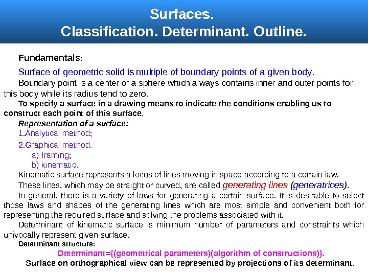
Surfaces. Classification. Determinant. Outline. Fundamentals : Surface of geometric solid is multiple of boundary points of a given body. B oundary point is a center of a sphere which always contains inner and outer points for this body while its radius tend to zero. To specify a surface in a drawing means to indicate the conditions enabling us to construct each point of this surface. Representation of a surface : 1. Analytical method ; 2. Graphical method. a ) framing; b ) kinematic. Kinematic surface represents a locus of lines moving in space according to a certain law. These lines, which may be straight or curved, are called generating lines ( generatrices ). In general, there is a variety of laws for generating a certain surface. It is desirable to select those laws and shapes of the generating lines which are most simple and convenient both for representing the required surface and solving the problems associated with it. Determinant of kinematic surface is minimum number of parameters and constraints which univocally represent given surface. Determinant structure : Determinant = {(geometrical parameters )( algorithm of constructions ) }. Surface on orthographical view can be represented by projections of its determinant.
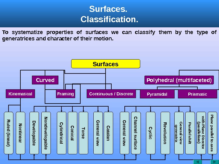
Surfaces. Classification. Surfaces Curved Polyhedral (multifaceted) Kinematical Framing. R uled (linear) N onlinear Prismatic. Pyramidal. Continuous / Discrete D evelopable C onical C ylindrical Torse G eneral view C hannel surface N ondevelopable G eneral view C atalan C yclic R evolution General view generatrix Parallel shift with Plane Director (parallelism ) Plane parallel to axes. To systematize properties of surfaces we can classify them by the type of generatrices and character of their motion.
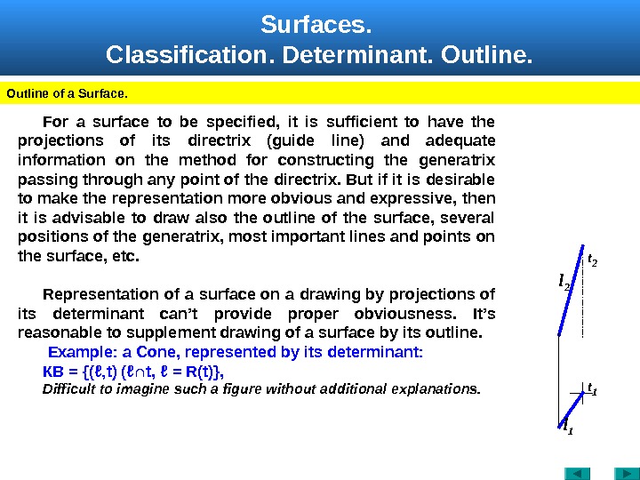
Surfaces. Classification. Determinant. Outline of a Surface. For a surface to be specified, it is sufficient to have the projections of its directrix (guide line) and adequate information on the method for constructing the generatrix passing through any point of the directrix. But if it is desirable to make the representation more obvious and expressive, then it is advisable to draw also the outline of the surface, several positions of the generatrix, most important lines and points on the surface, etc. Representation of a surface on a drawing by projections of its determinant can’t provide proper obviousness. It’s reasonable to supplement drawing of a surface by its outline. Example: a Cone, represented by its determinant : КВ = {(ℓ‚ t ) (ℓ∩ t , ℓ = R ( t )}, Difficult to imagine such a figure without additional explanations. t 2 l 1 t
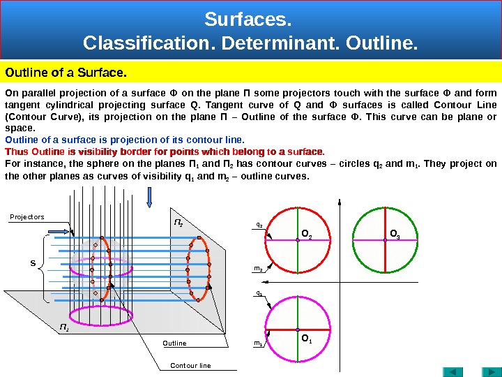
Surfaces. Classification. Determinant. Outline of a Surface. П 2 S Contour line Outline. Projectors O 1 O 2 O 3 П 1 On parallel projection of a surface Ф on the plane П some projectors touch with the surface Ф and form tangent cylindrical projecting surface Q. Tangent curve of Q and Ф surfaces is called Contour Line (Contour Curve), its projection on the plane П – Outline of the surface Ф. This curve can be plane or space. Outline of a surface is projection of its contour line. Thus Outline is visibility border for points which belong to a surface. For instance, the sphere on the planes П 1 and П 2 has contour curves – circles q 2 and m 1. They project on the other planes as curves of visibility q 1 and m 2 – outline curves. m 2 m 1 q 1 q
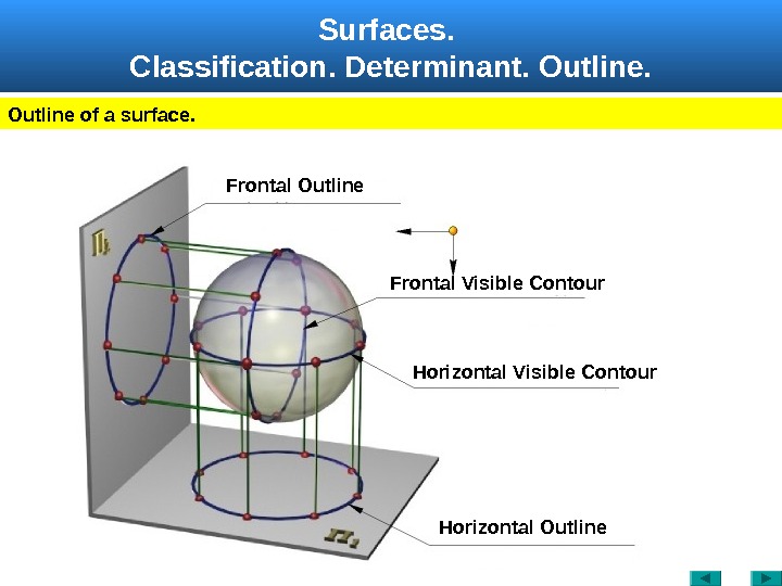
Surfaces. Classification. Determinant. Outline of a surface. Frontal Visible Contour. Frontal Outline Horizontal Visible Contour Horizontal Outline
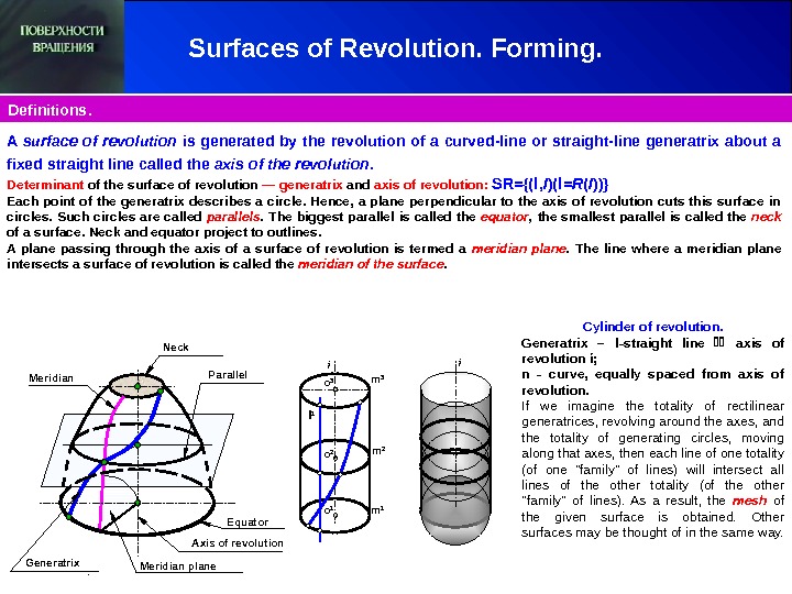
Surfaces of Revolution. Forming. Definitions. Parallel Meridian Generatrix Neck Axis of revolution l 1 i m 3 m 2 m 1 o 2 o 1 o 3 i Meridian plane. A surface of revolution is generated by the revolution of a curved-line or straight-line generatrix about a fixed straight line called the axis of the revolution. Determinant of the surface of revolution — generatrix and axis of revolution : SR = {( l , I )( l = R ( I ))} Each point of the generatrix describes a circle. Hence, a plane perpendicular to the axis of revolution cuts this surface in circles. Such circles are called parallels. The biggest parallel is called the equator , the smallest parallel is called the neck of a surface. Neck and equator project to outlines. A plane passing through the axis of a surface of revolution is termed a meridian plane. The line where a meridian plane intersects a surface of revolution is called the meridian of the surface. Equator Cylinder of revolution. Generatrix – l — straight line axis of revolution ί ; n — curve , equally spaced from axis of revolution. If we imagine the totality of rectilinear generatrices, revolving around the axes, and the totality of generating circles, moving along that axes, then each line of one totality (of one «family» of lines) will intersect all lines of the other totality (of the other «family» of lines). As a result, the mesh of the given surface is obtained. Other surfaces may be thought of in the same way.
Surfaces of Revolution. General.
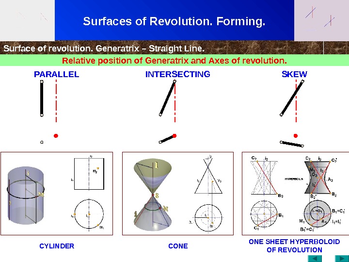
Surfaces of Revolution. Forming. Surface of revolution. Generatrix – Straight Line. Relative position of Generatrix and Axes of revolution. CYLINDER CONE SHEET HYPERBOLOID OF REVOLUTION PARALLEL INTERSECTING SKEW HYPERBOL
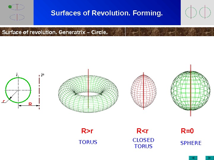
Surfaces of Revolution. Forming. Surface of revolution. Generatrix – Circle. R>r R<r R=0 i n Rr i TORUS CLOSED TORUS SPHER
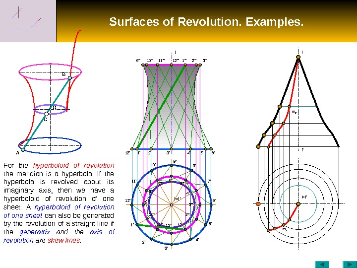
Surfaces of Revolution. Examples. C O B A 12′ I I=I ’10» 1′ 2′ 3′ 4′ 5′ 6’9 ‘ ‘ 11» 12» 1» 2» 3» I=I ‘ m 1 m 2 I ‘I 1’12’ 2’11’ 10′ 9′ 8′ 3′ 7′ 6′ 5′ 4’5» 4» 3» 2» 1»6» 10»9» 8» 7» 12»11»For the hyperboloid of revolution the meridian is a hyperbola. If the hyperbola is revolved about its imaginary axis, then we have a hyperboloid of revolution of one sheet. A hyperboloid of revolution of one sheet can also be generated by the revolution of a straight line if the generatrix and the axis of revolution are skew lines.
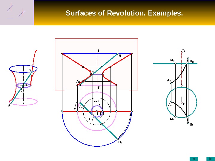
Surfaces of Revolution. Examples. C O B I I ‘ A B 1 B 2 A 1 B 1 A 2 B 2 M 2 t 1 t 2 C 2 I=I ‘A 1 C 1 M 1 Neck
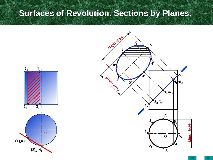
Surfaces of Revolution. Sections by Planes. O 14 23 2 2 21 2 (1) 1 =3 1 (2) 1 =4 1 1 1 8 1 2 1 3 1 4 1 5 16 17 11 2 2 2 =8 2 5 2 4 2 =6 2 3 2 =7 21′ 2’8′ 3’7′ 4’6′ 5′ O 1 Minor axes Major axes Minor axes
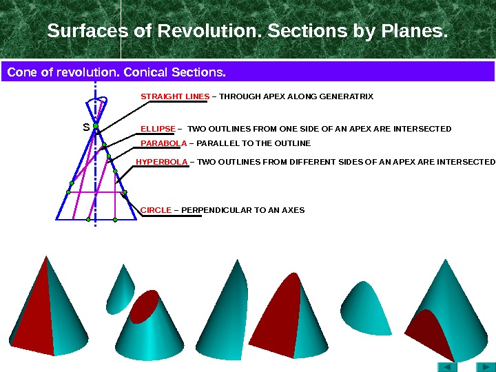
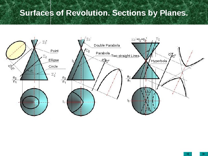
Surfaces of Revolution. Sections by Planes. S ELLIPSE – TWO OUTLINES FROM ONE SIDE OF AN APEX ARE INTERSECTED PARABOLA – PARALLEL TO THE OUTLINESTRAIGHT LINES – THROUGH APEX ALONG GENERATRIX HYPERBOLA – TWO OUTLINES FROM DIFFERENT SIDES OF AN APEX ARE INTERSECTED CIRCLE – PERPENDICULAR TO AN AXESCone of revolution. Conical Sections.
Surfaces of Revolution. Sections by Planes. Point Ellipse Circle Double Parabola Two straight Lines Hyperbola
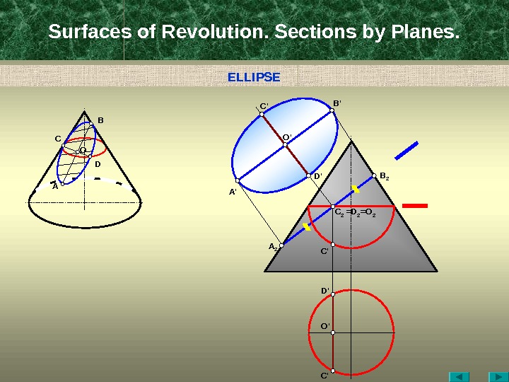
Surfaces of Revolution. Sections by Planes. A C B D D ‘ B ‘ C ‘ O ‘ A ‘ B 2 =D 2 =O 2 C 2 C ‘A 2 C ‘D ‘ O ‘O ELLIPS
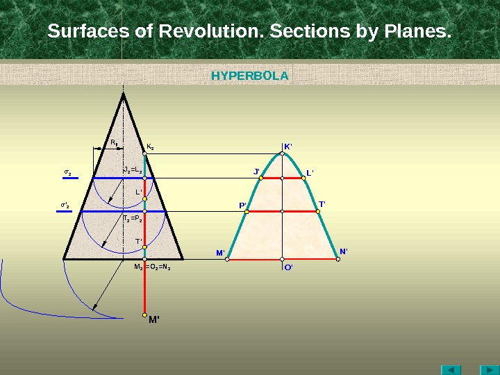
Surfaces of Revolution. Sections by Planes. O ‘M 2 =N 2=O 2 M ‘K 2 J 2 =L 2 L ‘ J ‘ N ‘K ‘ L’R jl T 2 = P 2 T ‘σ 2 σ ‘ 2 T ‘ P ‘HYPERBOL
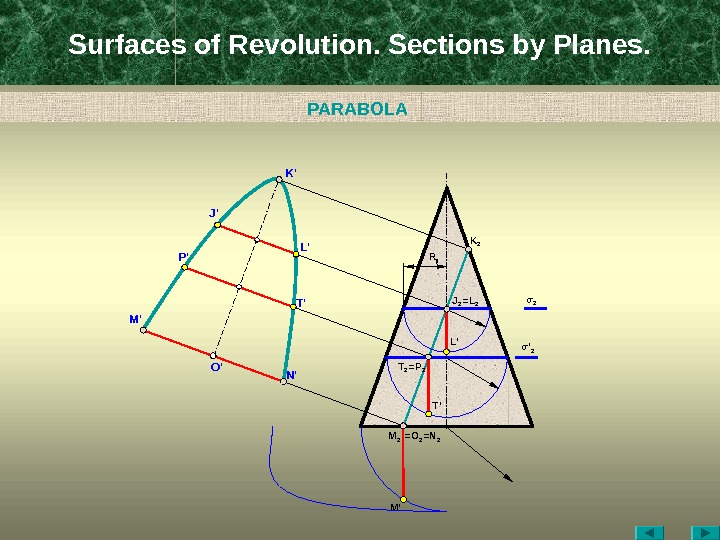
Surfaces of Revolution. Sections by Planes. O ‘ M 2 =N 2=O 2 M ‘M ‘ K 2 J 2 =L 2 L ‘J ‘ N ‘K ‘ L’ R jl T 2 = P 2 T ‘ σ 2 σ ‘ 2 T ‘P ‘ PARABOL
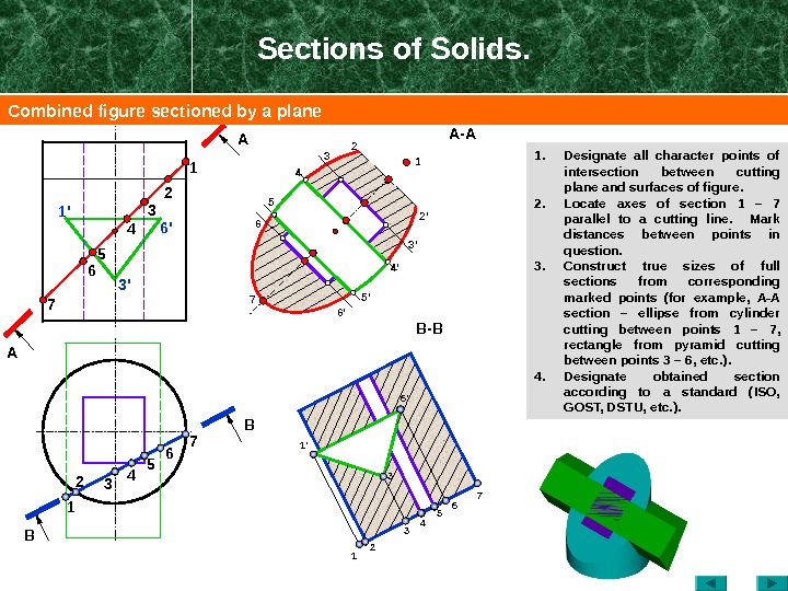
Sections of Solids. 1. Designate all character points of intersection between cutting plane and surfaces of figure. 2. Locate axes of section 1 – 7 parallel to a cutting line. Mark distances between points in question. 3. Construct true sizes of full sections from corresponding marked points ( for example, А-А section – ellipse from cylinder cutting between points 1 – 7 , rectangle from pyramid cutting between points 3 – 6 , etc. ). 4. Designate obtained section according to a standard (ISO, GOST, DSTU, etc. ). BA A B — B 2 2′ 71 2 3 4 5 6 7 7 6 5 4 1 22 1 4 3 6′ 3’1′ 3′ 6 ‘ 1 ‘ B 34 4’5 5′ A — A 3 3’6 6’ 1 Combined figure sectioned by a plane
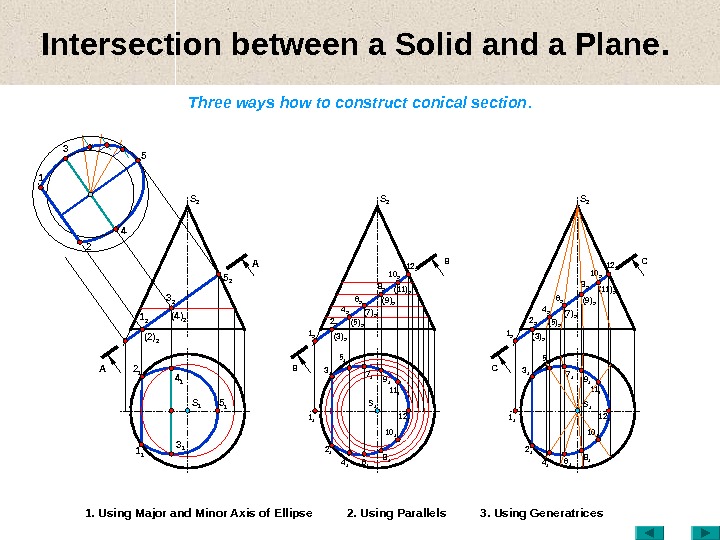
Intersection between a Solid and a Plane. Three ways how to construct conical section. 1. Using Major and Minor Axis of Ellipse 2. Using Parallels 3. Using Generatrices AA S 1 1 1 3 11 2 (2) 2 3 2 (4) 2 2 1 4 1 5 15 2 S 2 BB S 11 2 (3) 22 2 (5) 2 3 1 4 2 S 2 8 2 10 2 12 2 (11) 2 2 1 6 17 1 12 1 4 15 1 8 110 11 1 19 16 2 (7) 2 (9) 2 1 1 СС S 11 2 (3) 22 2 (5) 2 3 1 4 2 S 2 8 2 10 2 12 2 (11) 2 2 1 12 15 1 8 110 11 1 16 2 (7) 2 (9)
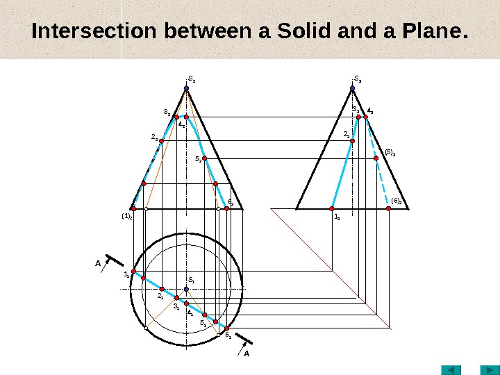
Intersection between a Solid and a Plane. S 1(1) 2 3 2 2 2 5 2 3 1 4 2 S 2 2 1 5 1 6 2 1 1 6 14 1 1 3 3 3 2 3 (5) 34 3 S 3 (6)
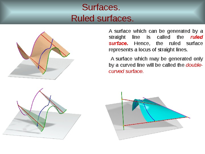
Surfaces. Ruled surfaces. A surface which can be generated by a straight line is called the ruled surface. Hence, the ruled surface represents a locus of straight lines. A surface which may be generated only by a curved line will be called the double- curved surface.
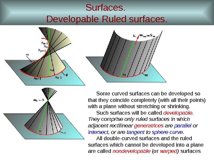
Surfaces. Developable Ruled surfaces. Some curved surfaces can be developed so that they coincide completely (with all their points) with a plane without stretching or shrinking. Such surfaces will be called developable. They comprise only ruled surfaces in which adjacent rectilinear generatrices are parallel or intersect , or are tangent to sphere curve. All double-curved surfaces and the ruled surfaces which cannot be developed into a plane are called nondevelopable (or warped ) surfaces
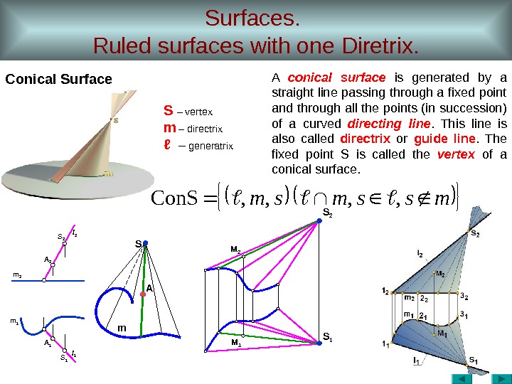
Surfaces. Ruled surfaces with one Diretrix. Conical Surface m 1 m 2 AS m M 2 M 1 S 2 l 1 A 1 S 1 mssmsm, , Con. S A conical surface is generated by a straight line passing through a fixed point and through all the points (in succession) of a curved directing line. This line is also called directrix or guide line. The fixed point S is called the vertex of a conical surface. S – vertex m – directrix ℓ – generatrix S 2 S
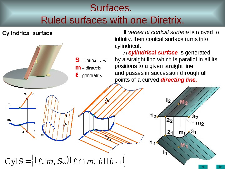
Surfaces. Ruled surfaces with one Diretrix. Cylindrical surface A 2 m 1 A 1 ml 1 A ll 2 A 11 ll, , , Cyl. Siillm. Sm If vertex of conical surface is moved to infinity, then conical surface turns into cylindrical. A cylindrical surface is generated by a straight line which is parallel in all its positions to a given straight line and passes in succession through all points of a curved directing line. S – vertex → ∞ m – directrix ℓ — generatrix
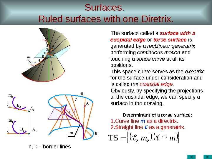
Surfaces. Ruled surfaces with one Diretrix. n , k – border linesmm, , TSl 1 m 1 B 1 m 2 l 2 B 2 A 1 A 2 l A m The surface called a surface with a cuspidal edge or torse surface is generated by a rectilinear generatrix performing continuous motion and touching a space curve at all its positions. This space curve serves as the directrix for the surface under consideration and is called the cuspidal edge. Obviously, by specifying the projections of the cuspidal edge, we can specify a surface in the drawing. Determinant of a torse surface : 1. Curve line m as a directrix. 2. Straight line ℓ as a generatrix. n k.
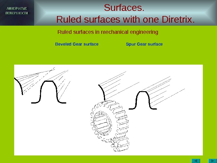
Surfaces. Ruled surfaces with one Diretrix. Ruled surfaces in mechanical engineering Beveled Gear surface Spur Gear surface
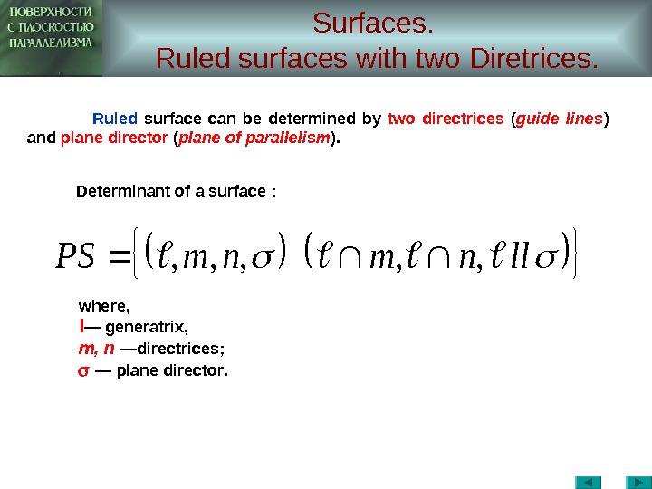
Surfaces. Ruled surfaces with two Diretrices. llnmnm. PS, , , where, l — generatrix , m , n — directrices ; — plane director. Ruled surface can be determined by two directrices ( guide lines ) and plane director ( plane of parallelism ). Determinant of a surface :
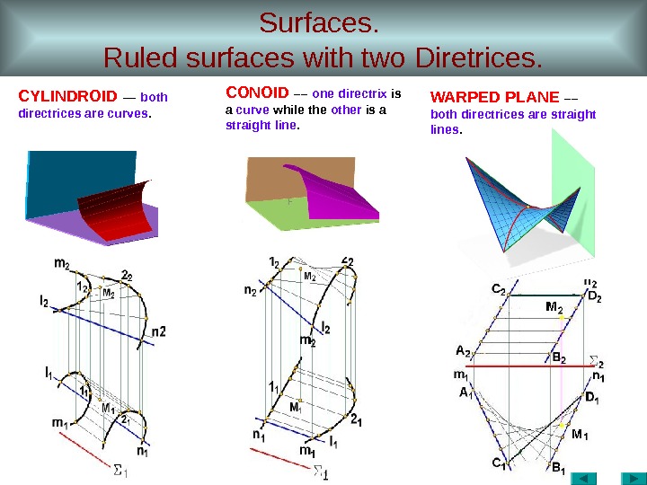
Surfaces. Ruled surfaces with two Diretrices. CYLINDROID –– both directrices are curves. CONOID –– one directrix is a curve while the other is a straight line. WARPED PLANE –– both directrices are straight lines.
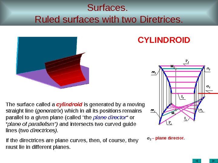
Surfaces. Ruled surfaces with two Diretrices. σ 2 – plane director. l 1 l ‘ 1 m 1 M 1 l 2 M 2 m 2 l ‘ 2 σ 2 n 2 n 1 CYLINDROID The surface called a cylindroid is generated by a moving straight line ( generatrix ) which in all its positions remains parallel to a given plane (called «the plane director “ plane of parallelism ” ) and intersects two curved guide lines (two directrices). If the directrices are plane curves, then, of course, they must lie in different planes.
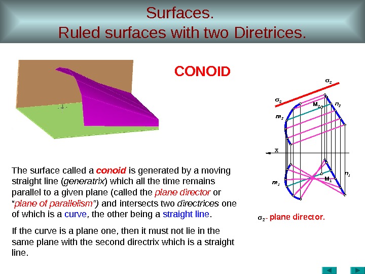
Surfaces. Ruled surfaces with two Diretrices. σ 2 — plane director. х m 2 n 1 m 1 σ 2 n 2 M 2 M 1 CONOID The surface called a conoid is generated by a moving straight line ( generatrix ) which all the time remains parallel to a given plane (called the plane director or “ plane of parallelism ” ) and intersects two directrices one of which is a curve , the other being a straight line. If the curve is a plane one, then it must not lie in the same plane with the second directrix which is a straight line.
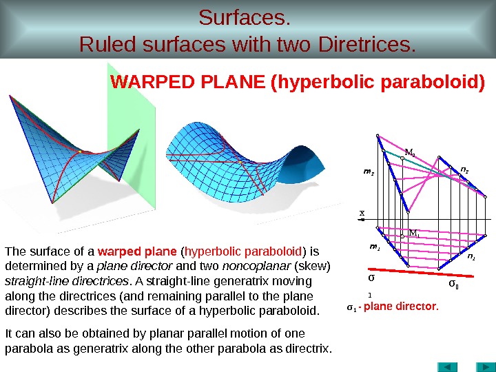
Surfaces. Ruled surfaces with two Diretrices. σ 1 — plane director. σ х σ m 2 M 1 n 2 n 1 m 1 M 2 The surface of a warped plane ( hyperbolic paraboloid ) is determined by a plane director and two noncoplanar (skew) straight-line directrices. A straight-line generatrix moving along the directrices (and remaining parallel to the plane director) describes the surface of a hyperbolic paraboloid. It can also be obtained by planar parallel motion of one parabola as generatrix along the other parabola as directrix. WARPED PLANE (hyperbolic paraboloid)
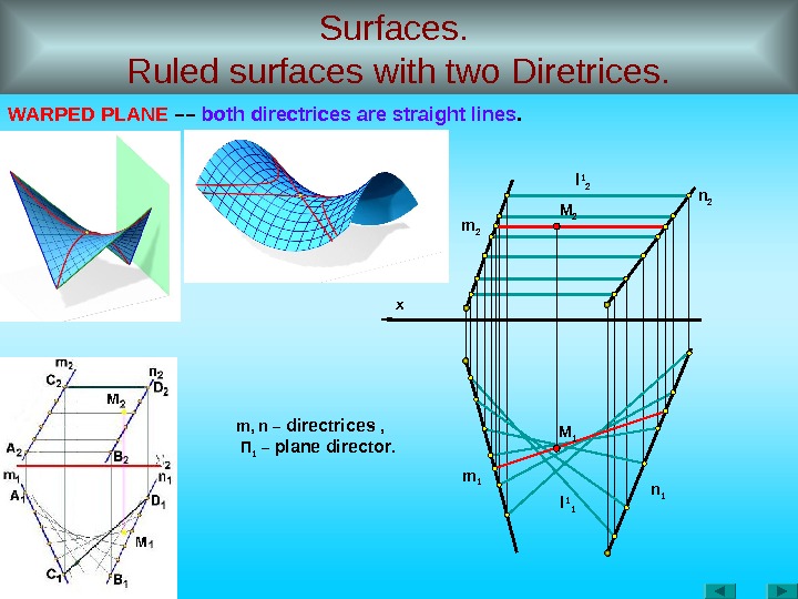
Surfaces. Ruled surfaces with two Diretrices. WARPED PLANE –– both directrices are straight lines. x m 2 n 1 m 1 m, n – directrices , П 1 – plane director. l 1 2 l 1 1 M 2 M
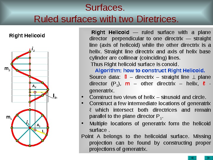
Surfaces. Ruled surfaces with two Diretrices. Right Helicoid — ruled surface with a plane director perpendicular to one directrix — straight line (axis of helicoid) while the other directrix is a helix. Straight line directrix and axis of helix base cylinder are collinear (coinciding) lines. Thus Right helicoid surface is conoid. Algorithm: how to construct Right Helicoid. Source data : – directrix – straight line plane director ( P 1 ), m – other directrix – helix , ℓ — generatrix. • Construct two views of helix – sinusoid and circle. • Construct a few intermediate locations of generatrix ℓ which intersect both directrices and remain parallel to the plane director P 1. • Multiple locations of generatrix form the helicoid surface . Point A belongs to the helicoidal surface. Missing projection can be found by constructing proper projections of generatrix. i 1 i 2 m 2 A 2 l 2 m 1 A 1 l
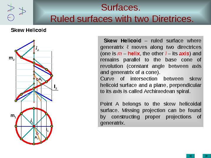
Surfaces. Ruled surfaces with two Diretrices. Skew Helicoid – ruled surface where generatrix ℓ moves along two directrices (one is m – helix , the other i – its axis ) and remains parallel to the base cone of revolution ( constant angle between axis and generatrix of a cone ). Curve of intersection between skew helicoid surface and a plane, perpendicular to its axis is called Archimedean spiral. Point A belongs to the skew helicoidal surface. Missing projection can be found by constructing proper projections of generatrix. i 1 i 2 m 2 A 2 l 2 m 1 A 1 l
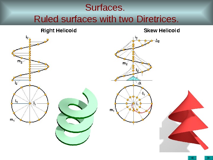
Surfaces. Ruled surfaces with two Diretrices. Right Helicoid Skew Helicoid
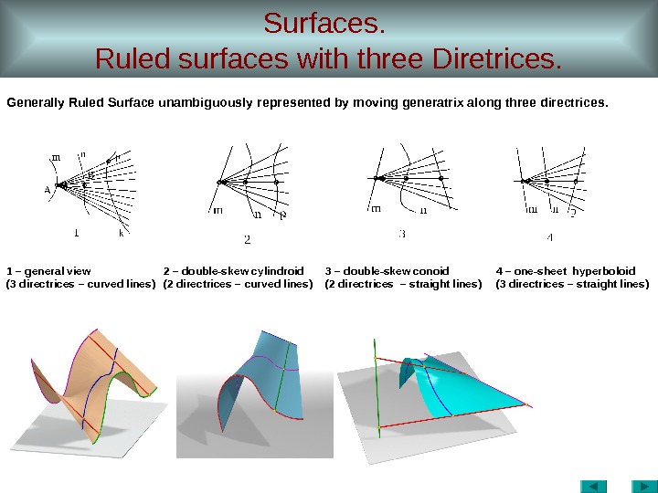
Surfaces. Ruled surfaces with three Diretrices. 1 – general view (3 directrices – curved lines ) 2 – double-skew cylindroid (2 directrices – curved lines ) 3 – double-skew conoid (2 directrices – straight lines ) 4 – one-sheet hyperboloid (3 directrices – straight lines ) Generally Ruled Surface unambiguously represented by moving generatrix along three directrices.
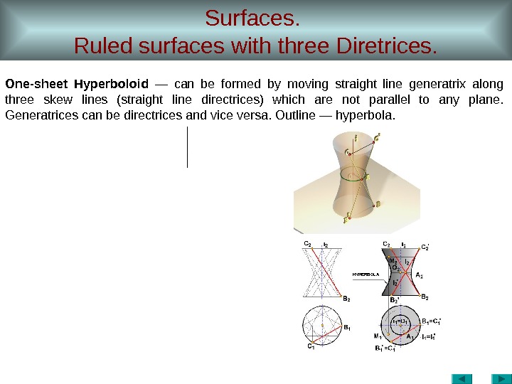
Surfaces. Ruled surfaces with three Diretrices. One-sheet Hyperboloid — can be formed by moving straight line generatrix along three skew lines (straight line directrices) which are not parallel to any plane. Generatrices can be directrices and vice versa. Outline — hyperbola. HYPERBOL
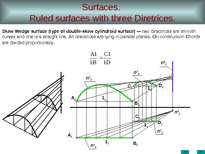
Surfaces. Ruled surfaces with three Diretrices. Skew Wedge surface ( type of double-skew cylindroid surface ) — two directrices are smooth curves and one is a straight line. All directrices are lying in parallel planes. On construction Chords are divided proportionally. А 1 1 1 D 1 В 1 С 1 1 1 А 2 1 2 D 2 В 2 С 2 1 2 n 1 2 n 2 2 n 3 1 n 2 1 n
Channel Surfaces.
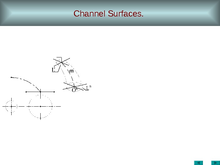
Channel Surfaces. O n L n. L 1 m
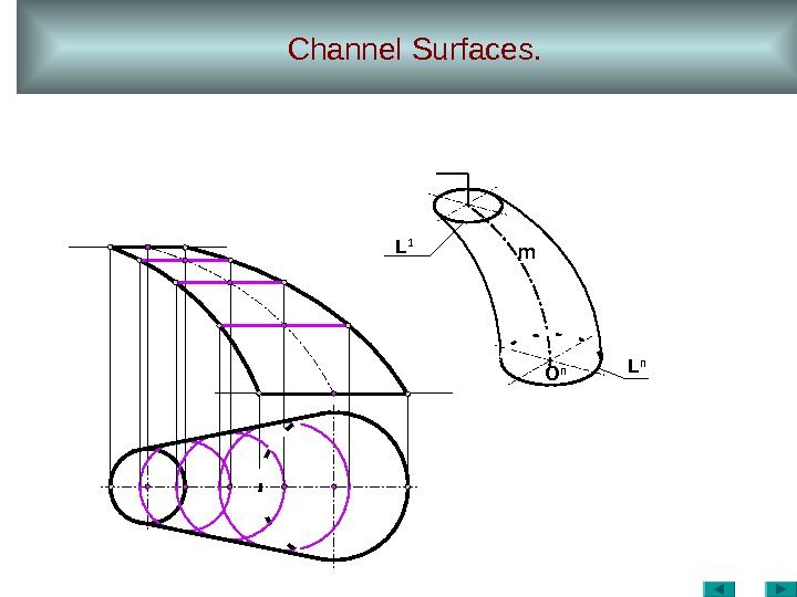
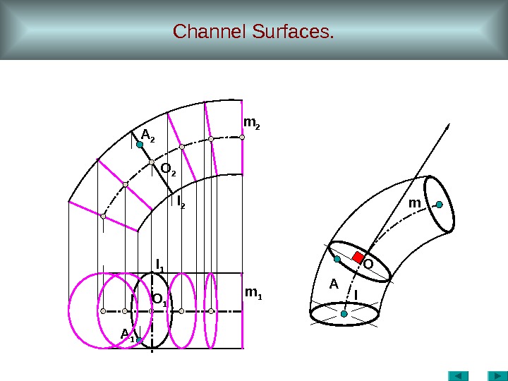
Channel Surfaces. A 1 A m 1 O 1 lm 2 l 1 O 2 A 2 O m
Channel Surfaces. 0 r=f()h 1=r h=F()
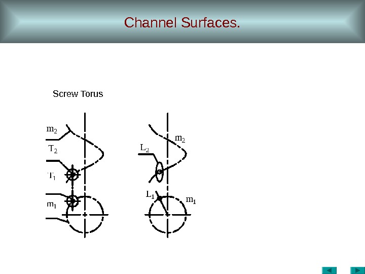
Channel Surfaces. Screw Torus
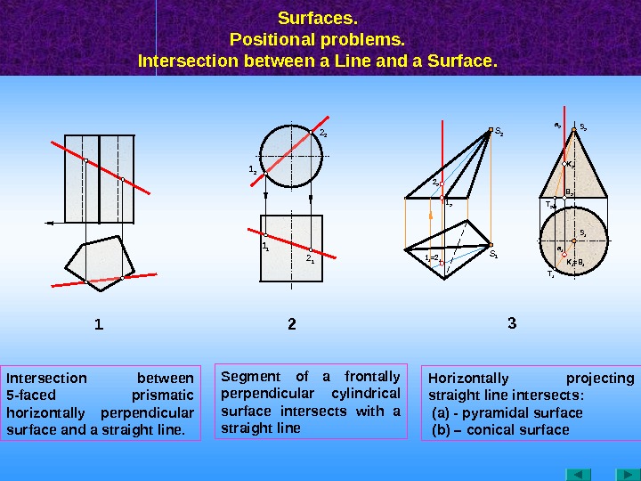
Surfaces. Positional problems. Intersection between a Line and a Surface. 1 1 1 21 2 2 2 T 11 1 =2 12 2 1 2 S 1 S 2 a 1 = B 1 K 1 B 2 T 2 S 1 K 2 a 2 S 2 3 Intersection between 5 — faced prismatic horizontally perpendicular surface and a straight line. Segment of a frontally perpendicular cylindrical surface intersects with a straight line Horizontally projecting straight line intersects: (а) — pyramidal surface ( b ) – conical surface
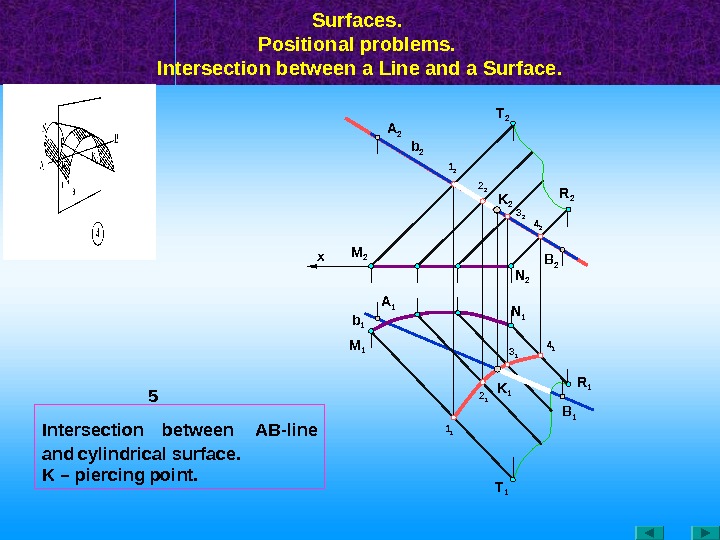
Surfaces. Positional problems. Intersection between a Line and a Surface. M 1 M 2 A 1 b 2 A 2 R 1 K 1 B 1 T 11 1 4 23 2 2 1 4 1 N 1 3 1 N 2 K 21 2 2 2 T 2 R 2 B 2 x 5 b 1 Intersection between АВ -line and cylindrical surface. K – piercing point.
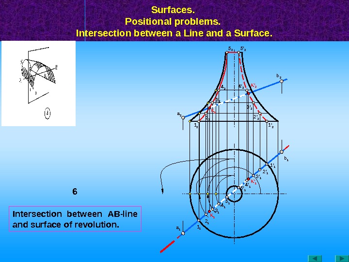
Intersection between АВ -line and surface of revolution. Surfaces. Positional problems. Intersection between a Line and a Surface. 6 a 1 1 1 a 2 K ‘ 1 1 ‘ 2 b 1 b 2 5 ‘ 1 2 1 3 1 4 1 5 1 4 ‘ 1 3 ‘ 1 2 ‘ 1 1 ‘ 1 K ‘ 2 K 1 2 ‘ 23 ‘ 24 ‘ 25 ‘
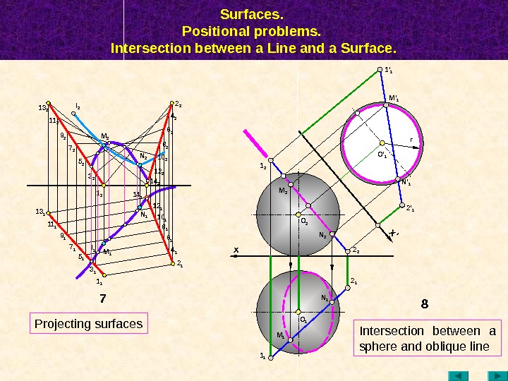
Surfaces. Positional problems. Intersection between a Line and a Surface. 81 2 N 2 1 1 x M 1 N 1 O 1 M 2 2 12 2 x’ 2 ‘ 1 M ‘ 11 ‘ 1 r O 2 N ‘ 1 7 N 114 113 2 11 2 9 1 l 1 5 17 1 1 1 M 1 M 2 3 25 2 11 1 7 29 2 l 2 1 2 6 1 2 14 18 110 112 2 12 114 2 8 2 6 24 2 2 2 1 3 1 N 2 10 2 O ‘ 1 Projecting surfaces Intersection between a sphere and oblique line
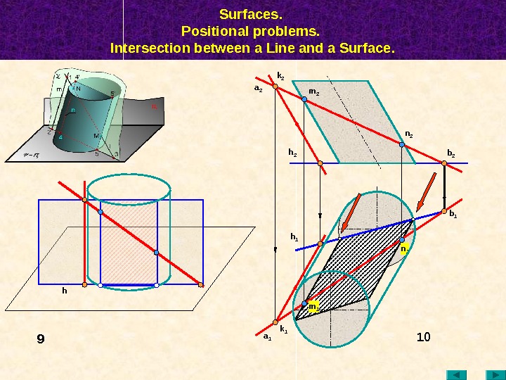
Surfaces. Positional problems. Intersection between a Line and a Surface. 10 a 2 k 2 a 1 k 1 h 2 h 1 b 1 b 2 m 2 n 2 m 1 n 1 h
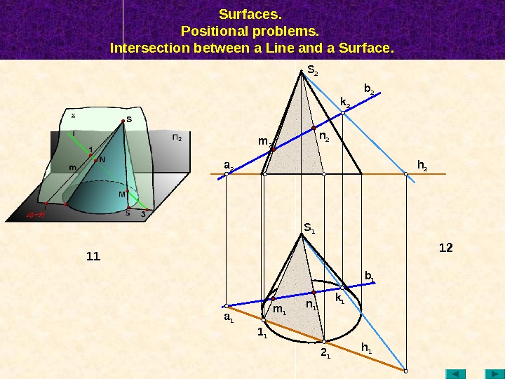
Surfaces. Positional problems. Intersection between a Line and a Surface. n 1 12 m 1 1 1 a 1 2 1 k 1 b 1 h 1 S 1 h 2 b 2 k 2 a 2 n 2 m 2 S
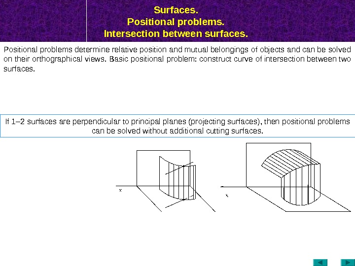
Surfaces. Positional problems. Intersection between surfaces. Positional problems determine relative position and mutual belongings of objects and can be solved on their orthographical views. Basic positional problem: construct curve of intersection between two surfaces. If 1– 2 surfaces are perpendicular to principal planes (projecting surfaces) , then positional problems can be solved without additional cutting surfaces.
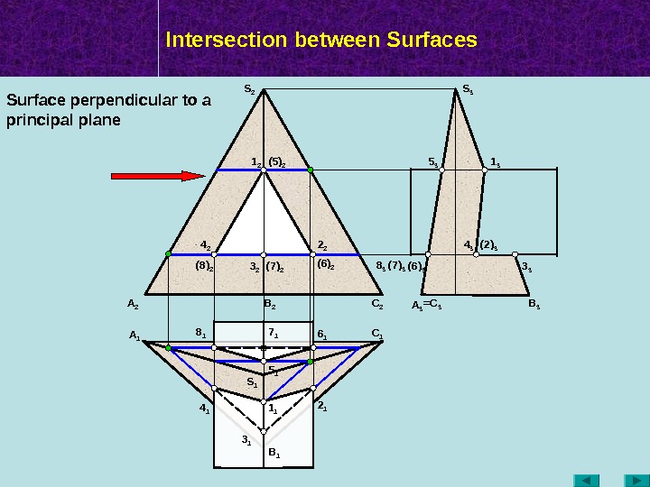
Intersection between Surfaces A 2 A 1 B 2 C 1 B 1 A 3 =C 3 B 3 S 2 S 3 S 11 2 3 2 (5) 2 (7) 2(8) 2 1 3 3 35 3 8 3 (7) 3 (6) 3 4 3 ( 2 ) 3 4 1 1 1 3 1 2 16 18 1 5 17 1 2 24 2 (6) 2 Surface perpendicular to a principal plane
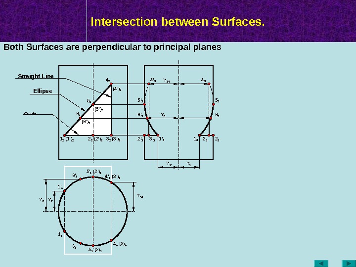
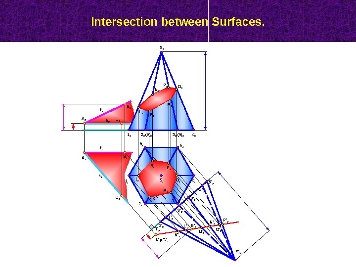
Intersection between Surfaces. Y 341 2 ( 2 ‘ ) 2 (3 ‘ ) 24 2 (5 ‘ ) 2 (4 ‘ ) 2 3 22 2(1 ‘ ) 2 5 2 1 1 4 1 (2) 1 (3) 1(3 ‘ ) 14 ‘ 1 5 1 (2 ‘ ) 15 ‘ 1 1 ‘ 1 Y 1 ‘Y 6 6 2 6 16 ‘ 1 ( 6 ‘ ) 2 Y 6 Y 1 ‘Y 34 Both Surfaces are perpendicular to principal planes Y 1 1 3 3 3 2 34 3 5 3 6 3 1 ‘ 33 ‘ 32 ‘ 36 ‘ 35 ‘ 3 4 ‘ 3 Circle Ellipse. Straight Line
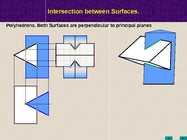
МТК Intersection between Surfaces. Polyhedrons. Both Surfaces are perpendicular to principal planes
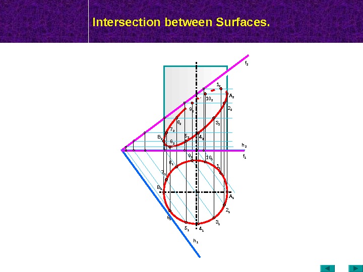
МТК Intersection between Surfaces. f 2 h 16 2 B 1 2 2 3 2 4 25 27 2 f 1 h
Intersection between Surfaces. B 2 A 2 C 1 B 1 A 1 1 1 2 1 3 1 4 15 16 1 S 1 4 23 2(6) 21 2 ( 5 ) 22 2 S ‘ 2 П ‘ 2 6 ‘ 2 4 ‘ 2 5 ‘ 2 3 ‘ 2 1 ‘ 2 2 ‘ 2 K ‘ 2 L ‘ 2 M ‘ 2 N ‘ 2 O ‘ 2 P ‘ 2 B ‘ 2 A ‘ 2 =C ‘ 2 K 1 L 1 N 1 M 1 P 1 O 1 L 2 N 2 P 2 O 2 M 2 K 2 h 1 f 2 f
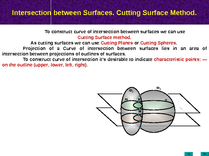
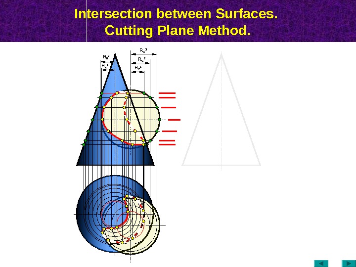
Intersection between Surfaces. Cutting Surface Method. To construct curve of intersection between surfaces we can use Cutting Surface method. As cutting surfaces we can use Cutting Planes or Cutting Spheres. Projection of a Curve of intersection between surfaces lies in an area of intersection between projections of outlines of surfaces. To construct curve of intersection it’s desirable to indicate characteristic points : — on the outline ( upper , lower , left , right ). Ф 2 n. Ф 1 m MN
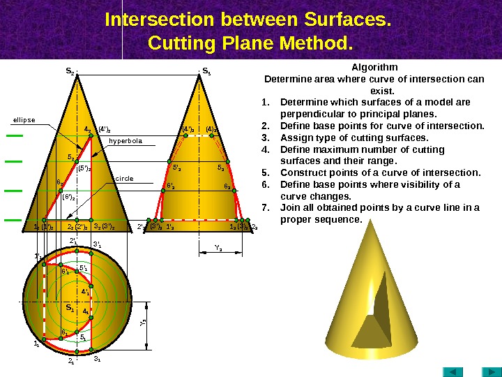
Intersection between Surfaces. Cutting Plane Method. S 2 ( 2 ‘ ) 2 (3 ‘ ) 24 2 (5 ‘ ) 2 (4 ‘ ) 2 3 22 25 2 (4 ‘ ) 3 (4) 3 6 36 ‘ 3 (3) 3 2 32 ‘ 3 1 11 ‘ 1 2 1 3 13 ‘ 12 ‘ 1 4 14 ‘ 1 6 16 ‘ 1 S 3 S 1 Algorithm Determine area where curve of intersection can exist. 1. Determine which surfaces of a model are perpendicular to principal planes. 2. Define base points for curve of intersection. 3. Assign type of cutting surfaces. 4. Define maximum number of cutting surfaces and their range. 5. Construct points of a curve of intersection. 6. Define base points where visibility of a curve changes. 7. Join all obtained points by a curve line in a proper sequence. (3 ‘ ) 3 1 3 hyperbolaellipse circle 6 2 (6 ‘ ) 2 5 35 ‘ 3 1 2 (1 ‘ ) 2 5 ‘ 1 5 1 Y 3 Y
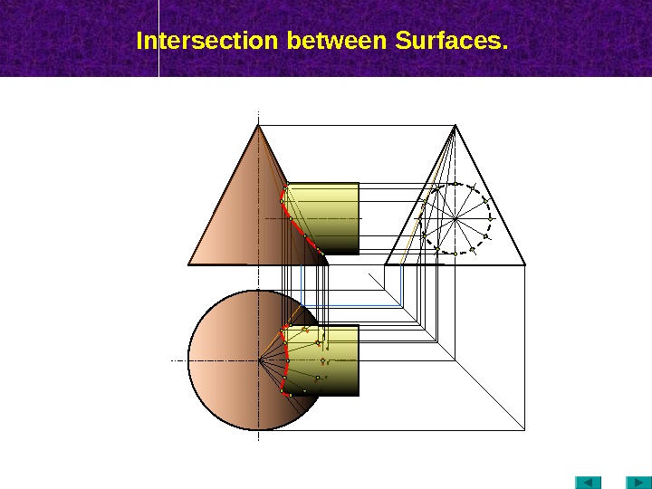
Intersection between Surfaces.
Intersection between Surfaces. Cutting Plane Method. R C 1 R C 2 R К 1 R К 2 R
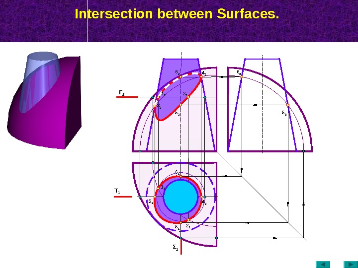
Intersection between Surfaces. Τ 1 Γ 2 2 11 1 4 23 2 Σ
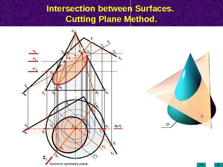
Intersection between Surfaces. Cutting Plane Method. а 16 1 8 1 4 14 2 9 2 3 1 Σ 1 Δ 1 = f 17 25 2 2 2 b 2 h 2 1 2 f 2 5 16 1 A 1 7 1 h ‘ 2 h » 2 а 2 B 1 D 1 S 1 2 1 h ‘ 2 b 13 28 1 A 2 B 2 C 2 1 1 Common symmetry plane S
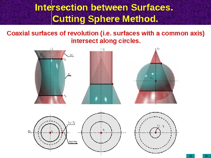
Intersection between Surfaces. Cutting Sphere Method. Coaxial surfaces of revolution (i. e. surfaces with a common axis) intersect along circles.
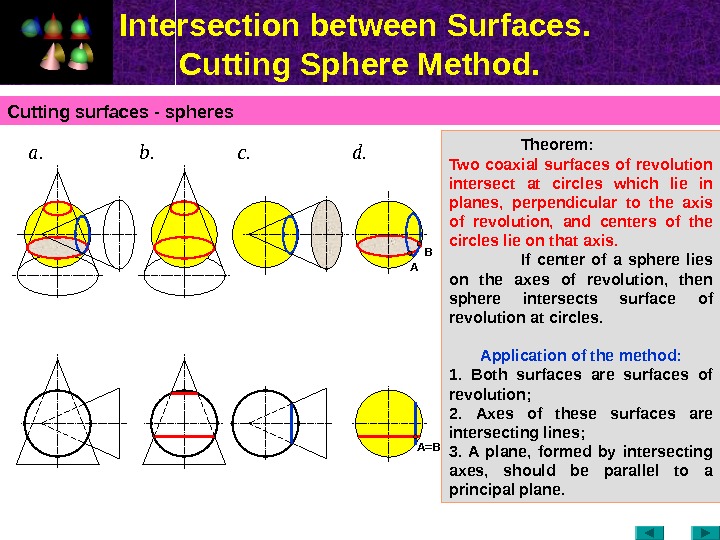
Intersection between Surfaces. Cutting Sphere Method. Cutting surfaces — spheres Theorem: Two coaxial surfaces of revolution intersect at circles which lie in planes, perpendicular to the axis of revolution, and centers of the circles lie on that axis. If center of a sphere lies on the axes of revolution, then sphere intersects surface of revolution at circles. Application of the method : 1. Both surfaces are surfaces of revolution ; 2. Axes of these surfaces are intersecting lines ; 3. A plane, formed by intersecting axes, should be parallel to a principal plane. а. c. b. d. A B A =
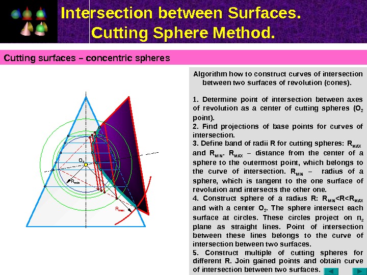
Intersection between Surfaces. Cutting Sphere Method. Algorithm how to construct curves of intersection between two surfaces of revolution (cones). 1. Determine point of intersection between axes of revolution as a center of cutting spheres (О 2 point ). 2. Find projections of base points for curves of intersection. 3. Define band of radii R for cutting spheres: R MAX and R MIN. R MAX – distance from the center of a sphere to the outermost point , which belongs to the curve of intersection. R MIN – radius of a sphere, which is tangent to the one surface of revolution and intersects the other one. 4. Construct sphere of a radius R: R MIN < R MAX and with a center О 2. The sphere intersect each surface at circles. These circles project on П 2 plane as straight lines. Point of intersection between these lines belongs to the curve of intersection between two surfaces. 5. Construct multiple of cutting spheres for different R. Join gained points and obtain curve of intersection between two surfaces. Cutting surfaces – concentric spheres O 2 R min R max
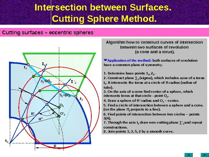
Intersection between Surfaces. Cutting Sphere Method. Cutting surfaces – eccentric spheres Algorithm how to construct curves of intersection between two surfaces of revolution (a cone and a torus). Application of the method: both surfaces of revolution have a common plane of symmetry. 1. Determine base points 1 2 , 2 2. 2. Construct plane ∑ 2 ( sigma ), which includes axes of a torus t 2. It intersects the torus at a circle of R-radius (radius of tube). 3. On the axis of a cone find center of a sphere, which intersects torus at that circle — point О 2. 4. Draw a sphere of R’-radius and О 2 – center. 5. Find a circle of intersection between a sphere and a cone. (on the plane П 2 projects to a line ). 6. Find points of intersection between two circles – points 3(4). 7. Through the axis t 2 draw new cutting plane ∑ ‘ 2 and repeat constructions. 8. Join points 1, 3, 5, 2 by a smooth curve. R’’O ‘ 2 O 2 R ’ t 2 3 21 2 5 2 2 2Σ 2 Σ ‘ 2=(4) 2 =(6) 2 R
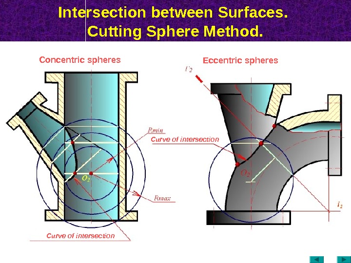
Intersection between Surfaces. Cutting Sphere Method. Curve of intersection. Concentric spheres Eccentric spheres
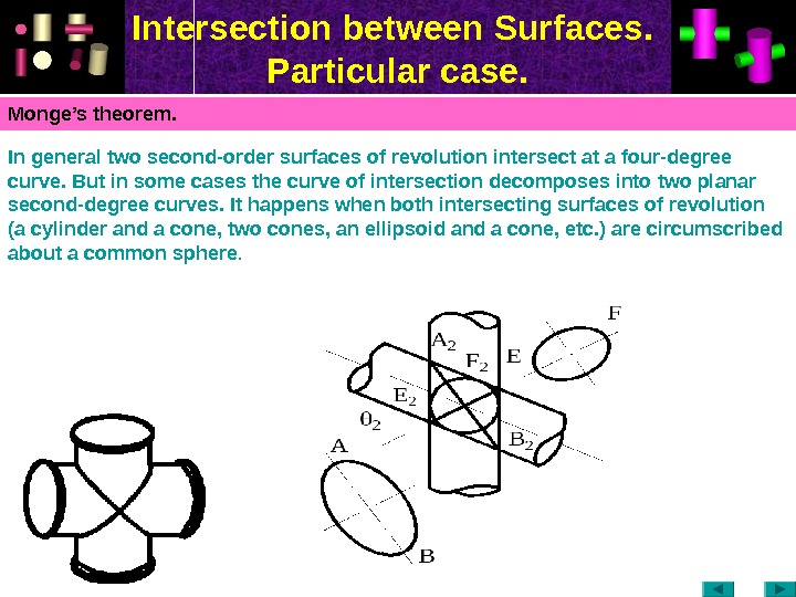
Intersection between Surfaces. Particular case. Monge’s theorem. In general two second-order surfaces of revolution intersect at a four-degree curve. But in some cases the curve of intersection decomposes into two planar second-degree curves. It happens when both intersecting surfaces of revolution (a cylinder and a cone, two cones, an ellipsoid and a cone, etc. ) are circumscribed about a common sphere.
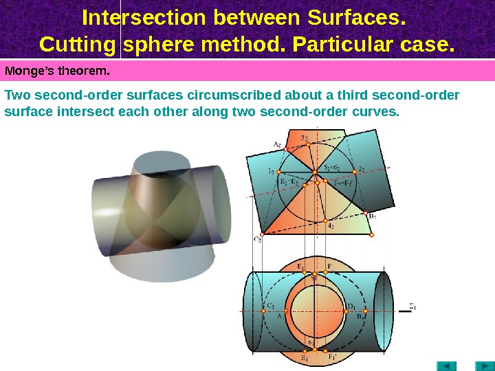
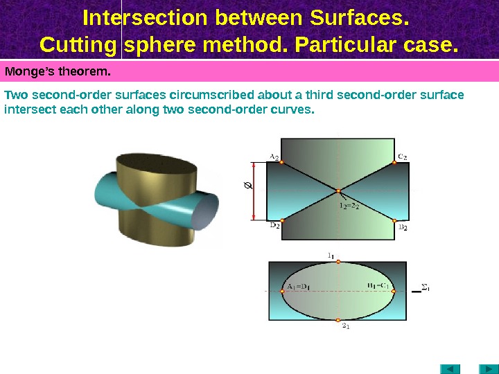
Intersection between Surfaces. Cutting sphere method. Particular case. Monge’s theorem. Two second-order surfaces circumscribed about a third second-order surface intersect each other along two second-order curves.
Intersection between Surfaces. Cutting sphere method. Particular case. Monge’s theorem. Two second-order surfaces circumscribed about a third second-order surface intersect each other along two second-order curves.
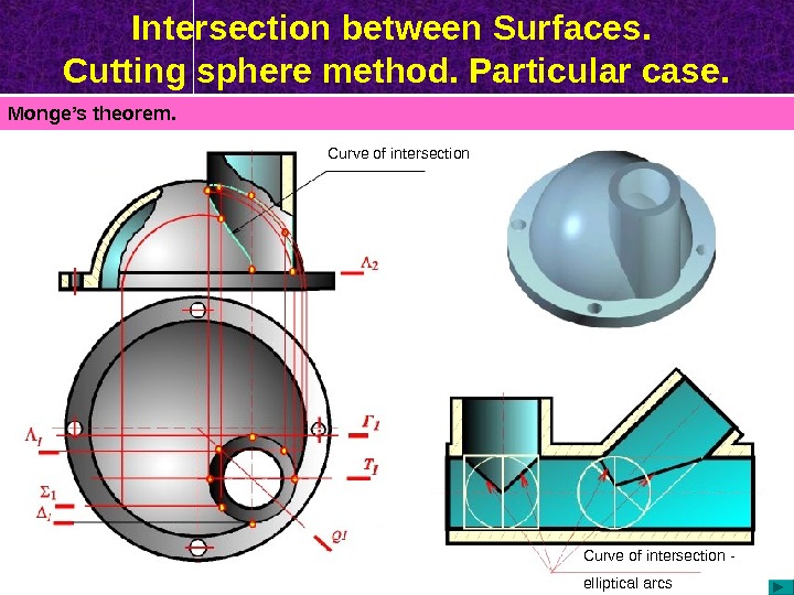
Intersection between Surfaces. Cutting sphere method. Particular case. Monge’s theorem. Curve of intersection — elliptical arcs
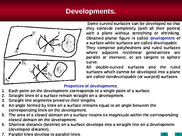
Developments. Properties of developments. 1. Each point on the development corresponds to a single point of a surface. 2. Straight lines of a surface remain straight on a development. 3. Straight line segments preserve their lengths. 4. An angle formed by lines on a surface remains equal to an angle between the corresponding lines on the development. 5. The area of a closed domain on a surface retains its magnitude within the corresponding closed domain on the development. 6. Shortest distance (beeline) on a surface develops into a straight line on a development (developed distance). 7. Parallel lines develop to parallel lines. Some curved surfaces can be developed so that they coincide completely (with all their points) with a plane without stretching or shrinking. Obtained planar figure is called development of a surface while surfaces are called developable. They comprise polyhedrons and ruled surfaces where adjacent rectilinear generatrices are parallel or intersect, or are tangent to sphere curve. All double-curved surfaces and the ruled surfaces which cannot be developed into a plane are called nondevelopable (or warped) surfaces.
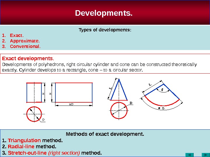
Methods of exact development. 1. Triangulation method. 2. Radial-line method. 3. Stretch-out-line (right section) method. Developments. Types of developments: 1. Exact. 2. Approximate. 3. Conventional. Exact developments. Developments of polyhedrons, right circular cylinder and cone can be constructed theoretically exactly. Cylinder develops to a rectangle, cone – to a circular sector. D D HH π D L L
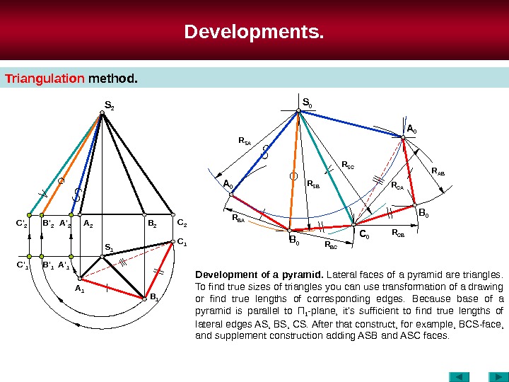
Developments. Triangulation method. Development of a pyramid. Lateral faces of a pyramid are triangles. To find true sizes of triangles you can use transformation of a drawing or find true lengths of corresponding edges. Because base of a pyramid is parallel to П 1 -plane, it’s sufficient to find true lengths of lateral edges AS , BS , CS. After that construct, for example, В CS-face, and supplement construction adding ASB and А SC faces. S 2 C 2 B 2 A 2 B ‘ 2 C ‘ 2 A ‘ 2 S 1 C 1 B 1 A 1 A ‘ 1 B ‘ 1 C ‘ 1 S 0 C 0 B 0 A 0 B 0 R SA R SB R S С R AB R С B R BCR BA R
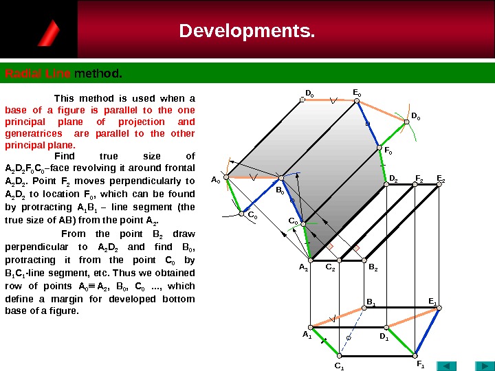
Developments. Radial Line method. C 0 A 1 A 2 C 0 A 0 B 0 D 1 C 1 F 1 B 1 C 2 B 2 E 1 F 0 F 2 D 2 E 0 D 0 This method is used when a base of a figure is parallel to the one principal plane of projection and generatrices are parallel to the other principal plane. Find true size of А 2 D 2 F 0 C 0 –face revolving it around frontal А 2 D 2. Point F 2 moves perpendicularly to А 2 D 2 to location F 0 , which can be found by protracting А 1 В 1 – line segment (the true size of АВ ) from the point А 2. From the point B 2 draw perpendicular to А 2 D 2 and find B 0 , protracting it from the point C 0 by В 1 С 1 -line segment, etc. Thus we obtained row of points А 0 А 2 , В 0 , С 0 . . . , which define a margin for developed bottom base of a figure.
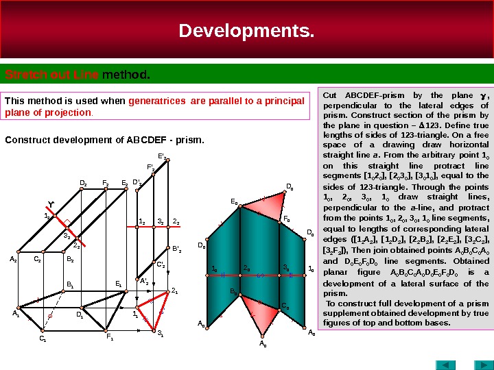
Developments. Stretch out Line method. This method is used when generatrices are parallel to a principal plane of projection. Cut ABCDEF-prism by the plane , perpendicular to the lateral edges of prism. Construct section of the prism by the plane in question – 123. Define true lengths of sides of 123 -triangle. On a free space of a drawing draw horizontal straight line a. From the arbitrary point 1 0 on this straight line protract line segments [1 0 2 0 ], [2 0 3 0 ], [3 0 1 0 ], equal to the sides of 123 -triangle. Through the points 1 0 , 2 0 , 3 0 , 1 0 draw straight lines , perpendicular to the a -line , and protract from the points 1 0 , 2 0 , 3 0 , 1 0 line segments , equal to lengths of corresponding lateral edges ([1 2 A 2 ], [1 2 D 2 ], [2 2 B 2 ], [2 2 E 2 ], [3 2 С 2 ], [3 2 F 2 ]), Then join obtained points A 0 B 0 C 0 A 0 and D 0 E 0 F 0 D 0 line segments. Obtained planar figure A 0 B 0 C 0 A 0 D 0 E 0 F 0 D 0 is a development of a lateral surface of the prism. To construct full development of a prism supplement obtained development by true figures of top and bottom bases. Construct development of ABCDEF — prism. A 1 C 1 D 1 F 1 A 2 B 21 2 2 2 A ‘ 2 C ‘ 2 B ‘ 2 A 0 B 0 C 0 A 01 1 D 0 F 0 E 0 D 0 2 01 0 3 0 1 0 D ‘ 2 E ‘ 2 2 23 21 2 E 2 F 2 D 2 D 0 A 0 B 1 E 1 C 2 3 2Ƴ 2 1 3 1 F ‘
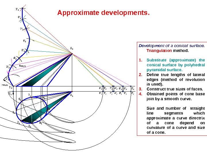
Development of a conical surface. Triangulation method. 1. Substitute (approximate) the conical surface by polyhedral pyramidal surface. 2. Define true lengths of lateral edges (method of revolution is used). 3. Construct true sizes of faces. 4. Obtained points of cone base join by a smooth curve. Size and number of straight line segments which approximate a curve directrix of a cone depend on curvature of a curve and size of a cone. Approximate developments. 1 1 S 2 S 1 2 1 3 1 5 16 17 1 8 11 ‘ 2 1 ‘ 1 6 ‘ 1 5 ‘ 1 7 ‘ 1 4 ‘ 1 8 ‘ 1 3 ‘ 1 2 ‘ 16 ‘ 2 5 ‘ 2 7 ‘ 2 4 ‘ 2 8 ‘ 2 3 ‘ 2 2 ‘ 23 ‘ 2 4 ‘ 2 5 ‘ 26 ‘ 27 ‘ 28 ‘ 21 ‘ 2 r =| 1 1 2 1 | R =|S 2 2 2 |
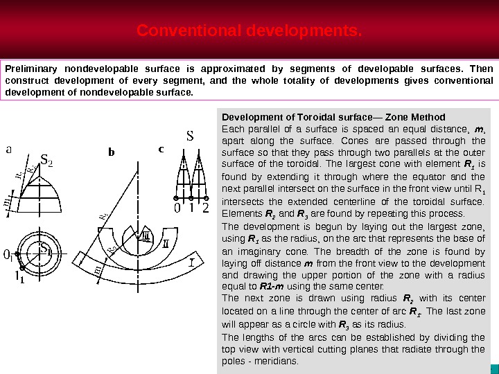
Conventional developments. Development of Toroidal surface— Zone Method Each parallel of a surface is spaced an equal distance, m , apart along the surface. Cones are passed through the surface so that they pass through two parallels at the outer surface of the toroidal. The largest cone with element R 1 is found by extending it through where the equator and the next parallel intersect on the surface in the front view until R 1 intersects the extended centerline of the toroidal surface. Elements R 2 and R 3 are found by repeating this process. The development is begun by laying out the largest zone, using R 1 as the radius, on the arc that represents the base of an imaginary cone. The breadth of the zone is found by laying off distance m from the front view to the development and drawing the upper portion of the zone with a radius equal to R 1 -m using the same center. The next zone is drawn using radius R 2 with its center located on a line through the center of arc R 1. The last zone will appear as a circle with R 3 as its radius. The lengths of the arcs can be established by dividing the top view with vertical cutting planes that radiate through the poles — meridians. Preliminary nondevelopable surface is approximated by segments of developable surfaces. Then construct development of every segment, and the whole totality of developments gives conventional development of nondevelopable surface. b c