8ba5719e594388af3f189d09d714806d.ppt
- Количество слайдов: 164
 Migration Toward 4 G and All-IP Concept
 Global Standardization Activities 3 GPP 2 ITU cdma 2000 IMT 2000 DDI-IDO ETSI TIA ARIB TTA CWTS TTC TIA T 1 CWTS 3 GPP WCDMA ETSI TTC TR 45. 4 CDMA/IS 95 Japan ITU HARMONIZATION TIA USA Europe SMG 2 GPRS/EDGE T 1 TR 45. 3 TDMA/UWCC TIA Page 2 WFI Confidential & Proprietary ARIB TTA ETSI Japan
 IMT 2000 Main Participants Korea EDGE ETSI WCDMA & TD-CDMA TTA (I & II) TIA TR 45. 5 & TR 45. 3 ITU-R Europe ARIB CDMA 2000 & UWC-136 U. S. Japan Industry Standard Groups ARIB - Association of Radio Industries and Business (Japan) ETSI - European Telecommunications Standards Institute (Europe) ITU - International Telecommunications Union TIA - Telecommunications Industry Association (USA) TTA - Telephone and Telegraph Association (S. Korea) Page 3 WFI Confidential & Proprietary
 IMT-2000 Radio Transmission Technology Candidates • Universal Wireless Communications (UWC-136) - USA TIA TR 45. 3 • Time-Division Synchronous CDMA (TD-SCDMA) - China Academy of Telecommunication Technology (CATT) • Wireless Multimedia & Messaging Services Wideband CDMA (WIMS: CDMA) USA TIA TR 46. 1 • UMTS Terrestrial Radio Access: Wideband CDMA (UTRA: W-CDMA) ETSI SMG 2 • Wideband CDMA (W-CDMA) - Japan ARIB • Wideband CDMA: IS-95 (cdma 2000) - USA TIA TR 45. 5 • Multiband synchronous DS-CDMA (CDMA I) - S. Korea TTA • Digital Enhanced Codeless Telecommunications (DECT) - ETSI Page 4 WFI Confidential & Proprietary
 Current Standardization Activities 3 GPP (Third Generation Project Partnership) Members: ETSI ARIB/TTC T 1 TTA CWTS System Specification: Access network: Core network Page 5 (Europe) (Japan) (USA) (S. Korea) (China -Associate) WCDAM (FDD) TDCDMA (TDD) Evolved GSM & All-IP WFI Confidential & Proprietary
 Current Standardization Activities 3 GPP 2 (Third Generation Project Partnership 2) Members: TIA ARIB/TTC TTA CWTS System Specification: Access network: Core network Page 6 (USA) (Japan) (S. Korea) (China) cdma 2000 (1 x & 3 x) Evolved IS-41& All-IP WFI Confidential & Proprietary
 Path to 3 G 1984 -1988 1989 -1999 14. 4 kbps 2000 -2002 144 kbps 2003 -2005 384 kbps 2 Mbps Today IS-136 EDGE i. DEN W-CDMA GPRS Analog Digital GSM IS-95 Source: CSFB Page 7 1 x. RTT WFI Confidential & Proprietary HDR CDMA 2000
 GSM Network Architecture AUC Base Station Subsystem (BSS) H EIR other BSSs A-bis A BTS Um BSC D G HLR F BTS other VLRs C VLR OMC B Mobile Services Switching Centre (MSC) BTS E MS other MSCs BTS: BSC: HLR: VLR: OMC: EIR: AUC: Page 8 PSTN ISDN CSPDN PSPDN WFI Confidential & Proprietary Base Transceiver Station Base Station Controller Home Location Register Visited Location Register Operation & Maintenance Centre Equipment Identity Register Authentication Centre
 GPRS Concept • The General Packet Radio Service (GPRS) 3 is a new value added service introduced in order to provide more efficient access to packet data networks from cellular networks. 3 utilizes packet switching technology where information is transmitted in short bursts of data over an IP-based network. 3 It provides a quick session set up and fast data transmission speeds. 3 3 Supports immediacy (no dial-up connection is necessary) It can use multiple time slots for data transfer as opposed to a normal single time slot. Enables the Internet applications not available previously on GSM networks It supplements today's Circuit Switched Data and Short Message Service in GSM networks. theoretically supports maximum speeds of up to 171. 2 kbps • GPRS shares GSM frequency bands with voice and circuit switched data traffic, and makes use of many properties of the physical layer of the original GSM system to simplify the introduction of new services Page 9 WFI Confidential & Proprietary
 GPRS Services and Applications • Supports two kinds of end-to-end packet switched data transfer: 3 Point-to-Point (PTP) services: – PTP connectionless network services for IP – PTP connection oriented network services for X. 25 3 Point-to-Multipoint (PTM) services: – PTM-M: Multicast services broadcasts packets in certain geographical areas – PTM-G: Group call services address packets to a group of users in a particular geographical area • Always on and pay per byte concept • New Applications Business Subscribers • Email/schedule • E-commerce • FTP i. e. file transfer • Web browsing • Emails Page 10 Consumers Subscribers • Banking • E-commerce • Information Services • Internet • Emails • WAP WFI Confidential & Proprietary
 Quality of Service • Qo. S classes are set per session, they include: 3 Service precedence: priority of a service in relation to other services 3 Reliability: required transmission characteristics (3 classes are defined) 3 Throughput: maximum peak bit-rate and the mean bit rate 3 Delay: maximum value of mean delay 3 Billing is based on data volume, type of service and Qo. S profile Page 11 WFI Confidential & Proprietary
 GPRS Mobile Classes • There are three classes of mobile stations (MSs) 3 Class A mobile station supports simultaneous operation of GPRS and conventional GPRS services 3 Class B mobile station is able to register with network for both GPRS and conventional GSM services simultaneously. In contrast to an MS of class A, it can only use one of the two services at a given time 3 Class C mobile station ca attach for either GPRS or conventional GSM services. Simultaneous registration or usage is not possible. An exception are SMS messages which can be received and sent at any time • Mobile stations also have different classes based on their multi-slot capabilities on the TX and RX sides 3 e. g. 3 Time slot Receive and 1 Transmit Page 12 WFI Confidential & Proprietary
 GPRS Main Attributes • Consists of packet wireless access network and IP-based backbone • Shares mobility databases with circuit voice services and adds new packet switching nodes (SGSN & GGSN) • Will support GPRS, EDGE & WCDMA air interfaces • Radio resources shared dynamically between speech and data services • GPRS is designed to minimize hardware modifications on existing network elements : 3 Addition of a new hardware component in the BSS, the PCU, which integrates most of the BSS new functions and manages RLC/MAC layers 3 BSC and BTS are impacted as few as possible 3 Entirely new core network with many functions, for the packet-switched services 3 The HLR is enhanced with GPRS subscriber data and routing information Page 13 WFI Confidential & Proprietary
 GPRS Network Components and Interfaces PSTN CN (Core Network) Gi Gc MSC/ VLR Gr Gs F EIR Gn SGSN Gf Abis BTS Um Page 14 CS (Circuit Switch) PS (Packet Switch) BSC Gb Gp CN (Core Network) RAN (Radio Access Network) A P C U 50 40 HLR/ AC D GGSN 10 0 C Gp Q GMSC PDN (Internet) CN (Core Network) Mobile data solution built upon the existing GSM Infrastructure and Mobility Management Gateway GPRS Support Node (GGSN) is responsible for routing data packets entering and leaving the radio network Serving GPRS Support Node is responsible for packet delivery to mobiles in different areas and interrogates the GSM databases for mobile profiles WFI Confidential & Proprietary
 GPRS Protocol Stack Application IP / X. 25 SNDCP LLC Relay LLC GTP UDP / TCP Relay GTP UDP / TCP IP IP RLC BSSGP MAC Network Service L 2 GSM RF L 1 bis L 1 MS Page 15 Um BSS Gb WFI Confidential & Proprietary SGSN Gn GGSN Gi
 Required Changes in the Current GSM Networks • GPRS is implemented on the top of GSM infrastructure by adding two main network elements: 3 Gateway GPRS support node (GGSN) 3 Serving GPRS Support Node (SGSN) • In addition to the new GPRS elements, existing GSM and TDMA (IS 136) network elements should also be enhanced in order to support GPRS. Following two must be enhanced: 3 Base Station System (BSS): must be enhanced (software upgrade) to recognize and send users data to SGSN that is serving the area. PCU interface is required to cater data traffic. 3 Home Location Register (HLR): changes (software upgrade) should be made in HLR to register GPRS user’s profile and respond to queries originating from SGSN’s regarding these profiles. 3 MSC/VLR: Existing hardware could be used but Software upgrade is required. • Mobile stations also need to be upgraded both in hardware and software to allow for multislot operation and variable coding. Page 16 WFI Confidential & Proprietary
 GGSN Functions • Acts as a logical interface between the GPRS network and the external public data networks such as IP and X. 25 • It converts the GPRS packets coming from SGSN into appropriate PDP format (e. g. , IP or X. 25) and sends them out on the corresponding packet data network (PDN). • It is connected to SGSNs via an IP GPRS backbone network • GGSN support routing functionality and manages information for attached/detached procedures for GPRS users • GGSN performs mobility management functions requesting location information from the HLR • GGSN is responsible for tunneling data, using GPRS Tunneling Protocol (GTP), to encapsulate and de-capsulate packets for delivery to SGSN Page 17 WFI Confidential & Proprietary
 SGSN Functions • SGSN is at the same hierarchical level as the MSC • SGSN responsible for the delivery of data packets from and to the mobile stations (MSs) within its service area • It is responsible for mobility management 3 SGSN keeps track of the individual MS’s location, attached and detached procedure 3 Interaction with VLR/HLR • SGSN supports authentication and charging functions Page 18 WFI Confidential & Proprietary
 PCU Functions • • GPRS radio resource allocation and management GPRS radio connection establishment and management Data transfer Coding scheme selection PCU statistics Interface with Billing Center It is possible that a single PCU (in this case known as PCU Serving Node) interacts with different BSCs BSC PCUSN P C U BSC Gb Agprs (Vendor defined) Page 19 WFI Confidential & Proprietary Frame Relay
 GPRS Protocol Stack (MS-BSS-SGSN) • LLC provides six Service Access Points (SAPs) to the upper layer protocols • SAPs act as tunnels to pass data between the layer 2 and layer 3 entities as follow: 3 Four SAPs are dedicated to the Subnetwork-Dependent Convergence Protocol (SNDCP) that manage data packet transmission 3 One SAP is dedicated to GPRS mobility management transmission 3 One SAP is dedicated to SMS • A Service Access Point Identifier (SAPI) identifies each SAP • A Data Link Connection Identifier (DLCI) identifies this logical link • A DLCI is composed of the SAPI at the LLC and the TLLI • SAPIs are points at which the LLC provides access to the SNDCP, that is Network SAPIs (NSAPIs) NSAPI 1 LLC SAPI 1 SAPI 2 MS Page 20 TLLI WFI Confidential & Proprietary LLC SGSN
 GPRS Protocol Stack (MS-BSS-SGSN) • The SAPIs that the LLC provides to the SNDCP layer are essentially the four Qo. S levels provided for data communications for different levels of reliability • In wireless data transmission, the logical link connections are maintained even when the lower layer physical link no longer exist (mobile is in idle state) Layer 3 GPRS Mobility Management GMM LLC Layer Logical Link Management Entity GMM SMS SNDCP Qo. S 1 Qo. S 2 Qo. S 3 Qo. S 4 Logical Link Entity SAPI=7 Logical Link Entity SAPI=11 Logical Link Entity SAPI=9 Logical Link Entity SAPI=5 Logical Link Entity SAPI=3 Entity SAPI=1 Multiplexing Procedure GRR RLC/MAC Layer (Mobile Station) Page 21 SMS WFI Confidential & Proprietary BSSGPP (SGSN)
 GPRS Protocol Stack (MS-BSS-SGSN) • The Logical Link management Entity (LLME) manages the resources that have an impact on individual connections • One LLME exists per TLLI and provides the following functions 3 Initializing the parameters to be used 3 Error processing 3 Invoking connection flow control Page 22 WFI Confidential & Proprietary
 GPRS Protocol Stack (MS-BSS-SGSN) • The SAPI parameter is in the address field of the LLC frame (4 bits) • The address field of the LLC frame is 1 octet (fixed) • There is a 3 octets (fixed) for frame check sequence (FCS) SAPI 7 0 1 octet Variable (max. 36 octets) PD C/R Not in use Address Field Control Field Variable 3 octets Page 23 Information Field FCS WFI Confidential & Proprietary
 Required Changes in the Current GSM Networks • GPRS is implemented on the top of GSM infrastructure by adding two main network elements: 3 Gateway GPRS support node (GGSN) 3 Serving GPRS Support Node (SGSN) • In addition to the new GPRS elements, existing GSM network elements should also be enhanced in order to support GPRS as follow: 3 Base Station System (BSS): must be enhanced (software upgrade) to recognize and send users data to SGSN that is serving the area. PCU interface is required to cater data traffic 3 Home Location Register (HLR): changes (software upgrade) should be made in HLR to register GPRS user’s profile and respond to queries originating from SGSN’s regarding these profiles 3 MSC/VLR: Existing hardware could be used but Software upgrade is required • Mobile stations also need to be upgraded both in hardware and software to allow for multi-slot operation and variable coding Page 24 WFI Confidential & Proprietary
 GPRS Physical Channels • Radio channels of GPRS are same as GSM 3 Same 200 KHz Carrier Spacing 3 Same Frame size 4. 615 ms 3 8 time slots per radio frame 3 Same GMSK modulation as GSM • More Flexible Resource Allocations: 3 Adds 4 Channel Coding Modes/Schemes (CS 1 -CS 4) 3 Allows Flexible and independent time slot allocation (1 -8) in the FW and Rev links 3 Radio resources shared dynamically between speech and data services Page 25 WFI Confidential & Proprietary
 GPRS Logical Channels Group Name PBCCH PRACH PPCH PCCCH PAGCH PNCH PDTCH PACCH Page 26 Direction Function Down-link Up-link Down-link Down & up-link Broadcast Random Access Paging Access Grant Multicast Data Associated ctrl WFI Confidential & Proprietary
 Packet Common Control Channels (PCCCHs) • Broadcast Channels: 3 Packet Broadcast Control Channels (PBCCH) – The PBCCH Transmits system information to all GPRS terminals in a cell • Common Channels: 3 Packet Random Access Channel (PRACH) – is used by the MSs to initiate packet transfers or respond to paging messages. – On this channel, MSs transmit access burst with long guard times. On receiving access bursts, the BSS assigns a timing advance to each terminal 3 Packet Paging Channel (PPCH) – is used to page an MS prior to downlink packet transfer – ? ? The PPCH is used for paging both circuit-switched and GPRS services, depending on the network operation modes and the class of mobile. (Class A or B will support this functionality). 3 Packet Access Grant Channel (PAGCH) – is used in the packet transfer establishment phase to send resource assignment to an MS prior to the packet transfer – ? ? Additional resource assignment messages are also sent on a PCCH if the mobile is already involved in packet transfer. 3 Packet Notification Channel (PNCH) – is used to send a PTM multicast notification to a group of MSs prior to a PTM packet transfer. The notification has the form of a resource assignment for the packet transfer Page 27 WFI Confidential & Proprietary
 Packet Traffic Channels (PTCHs) • Packet Data Traffic Channel (PDTCH) 3 It is used for data transfer. It is dedicated temporarily to one or a group of mobiles for multicast applications. 3 More than one PDTCH can be used in parallel (multislot operation) for individual packet transfers. The PDTCH can be shared between many users (8/PDTCH) • Packet Associated Control Channel (PACCH) 3 It is used to convey signaling information related to a given MS such as acknowledgements (ACK) and power control (PC) information. 3 also carries resource assignment messages, either for allocation of a PDTCH or further occurrences of a PACCH. 3 One PACCH is associated with one or several PDTCHs concurrently assigned to one MS • Packet Timing Advance Control Channel (PTCCH) 3 It is used in the uplink for transmission of random access burst. It allows the timing advance required by the mobile in the packet transfer mode to be estimated. 3 In the downlink, the PTCCH can be used to update the timing advance to multiple mobiles. Page 28 WFI Confidential & Proprietary
 Introducing GPRS in GSM • Two options are available for establishing GPRS air interface channels 3 Option 1 uses the GSM signaling resources but establishes separate packet data channels for traffic control. Traffic channels can be fixed or dynamic 3 Option 2 separates the GPRS resources entirely from those of GSM. There are several possible configurations with this option – A PBCH can be used to carry GPRS-BCH information, common control channels, GPRS packet data channels, and traffic-associated channels – If the packet data channels are not carried by the PBCH or if additional PDCH resources are required, separate timeslots can be configured Page 29 WFI Confidential & Proprietary
 Mixing or Separating PCCCH & CCCH • When no PCCCH is allocated in a cell, all GPRS attached MSs automatically camp on the existing GSM CCCH as they do in the idle state • The allocation of a PCCCH is the result of either an increased demand for packet data transfer or whenever there are enough physical channels in a cell • If the network releases the PCCCH, the MSs return to the CCCH Page 30 WFI Confidential & Proprietary
 GPRS Air Interface Protocol • A physical channel dedicated to packet traffic channel is called packet data channel (PDCH) • The allocation of TCHs and PDCHs is done dynamically according to the “capacity on demand” principle • A GPRS cell may have one or more PDCHs allocated from channels otherwise used as traffic channels (TCH) • The Master Slave Concept 3 At least one PDCH (mapped on one physical time slot) acts as a master 3 The master accommodates packet common control channels (PCCCHs) carrying control signaling for initiating packet transfer as well as user data and dedicated signaling. 3 The other channels, acting as slaves, are only used for user data transfer. • The existence of PDCHs does not imply the existence of PCCCH Page 31 WFI Confidential & Proprietary
 Capacity on Demand • The number of allocated PDCHs in a cell can be increased or decreased according to demand 3 Load supervision is done in the MAC layer to monitor the load on the PDCHs 3 Unused TCHs can be allocated as PDCHs to increase the overall Qo. S for GPRS. If services with higher priority request resources, reallocation of PDCHs can take place 3 This concept is used in cells with few or not GPRS users without the need for permanently allocated resources Page 32 WFI Confidential & Proprietary
 Mapping GPRS Packets to GSM Bursts Packet (N-PDU) PH Network Layer User data Segment LLC Frame FH Info Segment RLC Block BH Info LLC Layer RLC/MAC Layer Tail 456 Convolutional encoding 114 Burst SNDCP Layer Segment BSC 114 Burst PH : Packet header FH: Frame header BH: Block header Page 33 FSC Segment Normal burst Data Block Segment 114 Burst Physical Layer 114 Burst FCS: Frame check sequence BSC: Block check sequence WFI Confidential & Proprietary
 Packet Data Channel in GPRS TDMA frame 012 3 4 5 67 01 2 34 56 7 01 2 34 5 67 01 23 4 56 7 Idle burst 12 block structure (52 TDMA frames) Radio Block 456 bits Page 34 MAC Hdr RLC Data RLC Hdr (size depending on coding scheme) Coding/ puncturing WFI Confidential & Proprietary BCS PDCH 1 PDCH 0
 Random Access & Uplink Data Transmission MS BSS PRACH or RACH Packet channel request PAGCH or AGCH Packet immediate assignment PACCH Packet resource request PACCH Packet resource assignment Random access Transmission PDTCH PACCH PDTCH Frame transmission Negative acknowledgement Retransmission of blocks in error Acknowledgement PACCH Page 35 WFI Confidential & Proprietary
 Packet paging & Uplink Data Transmission MS PPCH or PCH PRACH or RACH PAGCH or AGCH PACCH or PAGCH or AGCH BSS Packet paging request Packet channel request Packet immediate assignment Packet paging response Packet resource assignment Paging Transmission PDTCH Frame transmission PACCH Negative acknowledgement PDTCH Retransmission of blocks in error PACCH Acknowledgement Page 36 WFI Confidential & Proprietary
 Dynamic Allocation of Time Slots (Example) Uplink state flag (MS allowed on uplink block) 1 Downlink Message type (downlink) and target MS Dt(3) 1 R Dt(3) 1 Dt(3) 2 1 1 PUA(2) 2 PCR(2) Dt(1) Dt(3) 1 1 TS 1 Dt(3) 1 Ack(2) TS 0 BSS ta Da R k PC Ac A PU MS 2 Uplink Dt(1) Dt(2) Dt(1) PCR: Packet channel request (PRACH) Ack: Packet uplink ack/nack (PACCH) PUA: Packet uplink assignment (PAGCH) PCA: Packet control acknowledgment Page 37 WFI Confidential & Proprietary TS 0 TS 1 Dt: Data block
 Routing Areas and Location Areas • One LA consists of a number of cells belonging to BSCs that are connected to the same core network node • One RA consists of a number of cells belonging to BSCs that are connected to the same core network node • One LA is handled by only one core network serving node (one combined MSC+SGSN) • One RA is handled by only one core network serving node (one combined MSC+SGSN) • The GSM/GPRS defined relations between LA and RA as follow: 3 RA and LA is equal in hierarchical level 3 One RA is a subset of one, and only one LA, meaning that a RA do not span more than on LA Cell RA Page 38 LA RA WFI Confidential & Proprietary
 GPRS Identities • International Mobile Subscriber Identity (IMSI) • Packet Temporary Mobile Subscriber Identity (P-TMSI) • Temporary Logical Link Identity (TLLI) 3 It is an identifier that uniquely identifies an MS within a routing area 3 Local TLLI (derived from P-TLLI), Random TLLI (generated by MS), 3 Foreign TLLI (derived from Local TLLI) • Network layer Service Access Point Identifier (NSAPI) • Tunneling Identity (TID which is =IMSI+NSAPI) • PDP address (IPv 4/6, X. 25, …) • Routing Area Identity (RAI which is =MCC+MNC+LAC+RAC) • GSN address 3 GSN number (SS 7 network), GSN address (IP address/logical name) • Access Point Name (APN) 3 DNS name of GGSN=route to external network Page 39 WFI Confidential & Proprietary
 PDP Context and Session Management • After GPRS attachment, to exchange data packets with external PDNs, the mobile must apply for one or more address used in the PDN: 3 An IP address in case of the IP networks 3 This is called a Packet Data Protocol address (PDP address) • For each session a PDP context is created describing its characteristics and includes: 3 PDP type (IPv 4, etc) 3 PDP address (172. 129. 23. 10) 3 Requested Qo. S 3 The address of the GGSN that serves as the access point to the PDN • The PDP context is stored in the following nodes: 3 MS 3 SGSN 3 GGSN Page 40 WFI Confidential & Proprietary
 PDP Address Allocation • PDP address allocation can be: 3 Static: User’s home PLMN network operator assigns a permanent PDP address to the user 3 Dynamic: A PDP address is assigned to the user upon activation of a PDP context, this can be assigned by: – Home PLMN (dynamic home PLMN PDP address) – Visited PLMN (dynamic visited PLMN PDP address) – The home PLMN decides which alternative is used • In the case of dynamic PDP address, the GGSN is responsible for the allocation and activation/deactivation of PDP address Page 41 WFI Confidential & Proprietary
 PDP Context Activation GGSN Gn MS Um BSS Gb SGSN Gn GGSN 1. Activate PDP Context 2. Create PDP Context Request 3. Create PDP Context Response 4. Activate PDP Context Accept Page 42 WFI Confidential & Proprietary
 Functional PDP State Model INACTIVE Deactivate PDP Context or MM state change to IDLE or PMM-DETACHED Activate PDP Context ACTIVE Page 43 WFI Confidential & Proprietary
 Definition of PDP States • A GPRS subscription contains the subscription of one or more PDP addresses • Each PDP address is described by one or more PDP contexts in the MS, SGSN and GGSN • Each PDP context may be associated with a Traffic Flow Template (TFT) • Every PDP context exists independently in one of two PDP states: 3 Inactive: The data service for a certain PDP address of a subscriber is not activated 3 Active: The PDP context for that address in use is activated in MS, SGSN and GGSN Page 44 WFI Confidential & Proprietary
 GPRS Network Access • Once a GPRS MS has begun operation, it introduces itself to the network by sending a “GPRS attach” request • Network access can be achieved from either fixed side or the mobile side of the GPRS network by making PTP and PMP available • As is cellular networks, several administrative functions are performed to validate user, including; 3 User Registration – Associates the mobile ID with user’s PDP (Packet Data Protocol) and address with in PLMN. Within the home area of the MS, traditional HLRs are enhanced to reference GPRS data. Outside the home area, dynamically allocated records are referenced in VLRs. 3 Authentication – Ensures the availability of GPRS MS and its associated services. GMM protocol (Mobility Management) functions are used for this part of signaling. 3 CAC (Call Admission Control) – it determines the required network resources for the Qo. S that is requested. It these resources are available, they will be reserved. Page 45 WFI Confidential & Proprietary
 GPRS Attach • Network can/should check MS’s identity • Download MS’s subscription information from HLR to SGSN (if SGSN doesn’t already have that info) • Update MSC/VLR (if IMSI Attach is also performed) • Attach types 3 Attach the first time 3 Attach again in the same SGSN 3 Attach again in a new SGSN 3 Attach when SGSN has detected the context Page 46 WFI Confidential & Proprietary
 GPRS Attach Procedure (1) • The request for a GPRS attach is made to the SGSN • Mobile sends SGSN its identity as an IMSI (international mobile subscriber identity) or P-TMSI (packet temporary mobile subscriber identity), this message will also contain a: 3 Network Service Area Point Identifier (NSAPI), which is specific to a particular network application at the mobile station. SNDCP layer uses this to communicate with the network applications (Internet browser, email, etc have their own NSAPI) • The latter indicates to the SGSN whether the mobile wants to attach as a GPRS device, a GSM device, or both • The SGSN will attach the mobile and inform the HLR if there has been a change in the RAI, if the desired attach type is both GPRS and GSM, the SGSN will also update the location with the VLR, provided that the Gs interface exists • Note that a GPRS attach does not enable the mobile phone to transmit and receive data, for this, the mobile has to activate a communication session using PDP context Page 47 WFI Confidential & Proprietary
 GPRS Attach Procedure (2) • After authorization, the SGSN sends back a reply to the mobile station with a Temporary Logical Link Identifier (TLLI) • The TLLI is specific to the mobile and is used by the LLC layer to provide a temporary ID to the mobile station, which can be used for a data communication • A database is maintained at the SGSN that maps the mobile identity with the TLLI assigned to it, the NSAPI is associated with and the QOS subscription parameters required by the application MS 1 TLLI=1, NSAPI=2 MS 2 TLLI=2, NSAPI=3 MS 3 More files to come after activation TLLI=3, NSAPI=2 Table update example for SGSN with 3 attached users Page 48 WFI Confidential & Proprietary
 GPRS Attach Procedure MS Um Gb BSS SGSN Gs VLR MAP 1. Attach Request 2. Security Procedures 3. Location Update 4. Location Update 5. Attach Accept Page 49 WFI Confidential & Proprietary VLR
 GPRS Detach Procedure (1) • GPRS detach procedure allows: 3 MS to inform the network that it does not want access the SGSN-based services any longer 3 The network to inform the MS that it does not have access to the SGSN- based service anymore • Different types of detach are: 3 IMSI detach 3 GPRS detach 3 combine GPRS/IMSI detach (MS initiated only) Page 50 WFI Confidential & Proprietary
 GPRS Detach Procedure (2) • There two different ways for detaching a MS: 3 Explicit: The network or the MS explicitly requested detach – A Detached Request is sent by the SGSN to the MS, or by the MS to the SGSN 3 Implicit: The network detached the MS without notifying the MS • The MS can make an IMSI detach in one of two ways depending on if it is GPRS-attached or not: 3 A GPRS-attached MS sends a Detached Request message to SGSN, indicating and IMSI detach 3 A MS that is not GPRS-attached makes the IMSI detach as already defined in GSM • In the network-originated Detach Request message there may be an indication to tell the MS that it is requested to initiate GPRS attach and PDP context activation procedure for the previously activated PDP contexts Page 51 WFI Confidential & Proprietary
 Mobility Management Main Issues • The main task of mobility management is to keep track of the user’s current location, so that in coming packets can be router to his/her MS • The main issues in mobility management are as follow: 3 READY timer function 3 Periodic RA update timer function 3 Mobile reachable timer function Page 52 WFI Confidential & Proprietary
 Mobility Management • As a mobile station moves from one area to another, mobility management functions are used to track its location within each PLMN • The mobile station's profiles are preserved in the VLRs that are accessible to SGSNs via the local MSC • A logical link is established and maintained between the mobile station and the SGSN at each PLMN • At the end of transmission or when a mobile station moves out of the area of a specific SGSN, the logical link is released and the resources associated with it can be reallocated Page 53 WFI Confidential & Proprietary
 Mobility Management-MS State • IDLE: The subscriber is not attached to the GPRS MM • STANDBY: The subscriber is attached to the GPRS MM • READY: The SGSN MM context extended by location information for the subscriber on cell level IDLE GPRS Detach GPRS Attach READY timer expiry or Force STANDYBY PDU Transmission STANDBY MM State model of MS Page 54 WFI Confidential & Proprietary
 Mobility Management-SGSN Model state • This function of Mobility Management (MM) is needed in GPRS to 3 Attach: know who is the MS and what it can or is allowed to do. 3 Detach: leaving the system 3 Location update: know the location of MS IDLE Implicit Detach or Cancel Location GPRS Detach or Cancel location GPRS Attach • In the STANDBY state the subscriber is known in the accuracy of the RA • In the READY state the subscriber is know in the accuracy of the LA (cell) READY timer expiry or Force STANDYBY PDU reception STANDBY MM State Model of SGSN Page 55 WFI Confidential & Proprietary
 Mobility Management- RA and LA Update • Interaction between SGSN and MSC/VLR 3 IMSI attached and detached via SGSN 3 Co-ordination of LA update and RA update, including periodic updates 3 Paging for a CS connection via the SGSN 3 Alert procedures for non-PS services 3 Identification procedure 3 MM information procedure Page 56 WFI Confidential & Proprietary
 Routing and Data Transfer • Once a mobile station begins data transmission, routing is performed by the GSNs on a hop-by-hop basis through the mobile network using the destination address in the message header • Routing tables are maintained by the GSNs utilizing the GTP layer which may carry out Address Translation and Mapping functions to convert the external PDN addresses to an address that is usable for routing within PLMNs. • The data itself will go through several transformations as it travels through the network • Depending on the destination PDN, the data can be: 3 Forwarded, using the relay function, to go from one node to the other in the route, 3 Tunneled to transfer data from one PLMN to another, 3 Compressed to use the radio path in an efficient manner (Compression algorithms may be used for manufacturers to differentiate themselves, however, they may face interoperability issues in heterogeneous networks), and/or 3 Encrypted to protect the mobile station from eavesdropping (Encryption algorithms can also be used as a differentiating factor). Page 57 WFI Confidential & Proprietary
 Location Management-Routing Area Update • When MS changes RA 3 It tells to the network (old RA) it came from 3 MS doesn’t know if SGSN changes – Simple update , if same SGSN handles both RA’s – If SGSN changes, then – get MS’s active information from the old SGSN – new SGSN needs to get user’s subscription information from HLR – all GGSN’s must be updated • MS detects RA change but not SGSN changes • Intra-SGSN routing area update 3 No need to update HLR or GGSN • Inter-SGSN routing area update 3 Both HLR and GGSN need to be updated Page 58 WFI Confidential & Proprietary
 Session Setup Example PSTN/ISDN IP HLR IP Address exists! GMSC GGSN SGSN MSC BTS Page 59 I want to do packet Set up a context Tunnel created Radio link established WFI Confidential & Proprietary
 Packet Forwarding Example PSTN/ISDN IP HLR ? GMSC ? MSC BTS Page 60 163. 42. 143 GGSN SGSN Inbound packet Where is the mobile? This tunnel! Where is the mobile? This radio link! Allocate a few bursts and send it! WFI Confidential & Proprietary
 RA Reselection Example PSTN/ISDN IP HLR Still same IP address! GMSC GGSN SGSN MSC BSC Tunnel created Radio link established I’m here now OK, new link and tunnel BTS Page 61 WFI Confidential & Proprietary
 GSM/GPRS Link Budget Comparison (1) • The Receiver Sensitivity depends on the coding scheme 3 Each type of modulation and coding scheme requires, for a given BLER, different minimum Eb/No 3 As the data rates increases the error protection is reduced and therefore more Eb/No is required to meet the same BLER, this translates into different receiver sensitivities associated to each coding scheme • There is smaller or no body loss 3 The typical 3 d. B body loss associated with voice service is excluded from the GPRS link budget (the user does not use the MS close to his/her head) 3 Due to this 3 d. B, the cell radius for CS 1 (CS 2) is larger (equal) than for voice service Page 62 WFI Confidential & Proprietary
 GSM/GPRS Link Budget Comparison (2) • The Down-link Interference Level Increase 3 The effect of GPRS load on the existing GSM service will be of the order of up to 2 d. B degradation in the down-link TCHs – Since down link GPRS power control will not be used, extra load is anticipated that will increase the interference level when GPRS services are introduced 3 No effect is anticipated on the down-link BCCH – Permanently keyed carriers and the absence of down-link power control serve to keep the interference at a fixed amount 3 Power control is implemented in the up-link case, hence, the effect of the GPRS traffic is not a problem and there is no differences between BCCH and TCH cases • Different Coding Schemes can be used in different parts of markets depending on 3 The future demand for the data rates and marketing strategies 3 The ability to offer different coding schemes without (or the minimum) modification in the existing network Page 63 WFI Confidential & Proprietary
 GSM/GPRS Link Budget Promoters (Examples) Receiver Sensitivity Effect Body Loss Effect Page 64 WFI Confidential & Proprietary
 Coding Schemes and Coverage Impact Page 65 WFI Confidential & Proprietary
 A Review of UMTS
 UMTS Goals “UMTS will be a mobile communications system that can offer significant user benefits including high-quality wireless multimedia services to a convergent network of fixed, cellular and satellite components. It will deliver information directly to users and provide them with access to new and innovative services and applications. It will offer mobile personalised communications to the mass market regardless of location, network and terminal used”. UMTS Forum 1997 Page 67 WFI Confidential & Proprietary
 UMTS Vision Page 68 WFI Confidential & Proprietary
 UMTS Bearer Services • The UMTS radio access network and fixed network are expected to provide four classes of bearer services: 3 Class A - Circuit-switched bit pipe 3 Class B - Circuit-switched bit pipe for variable bit rate 3 Class C - Connection-oriented packet switched bearer service 3 Class D - Connectionless packet switched bearer service Page 69 WFI Confidential & Proprietary
 UMTS Services Capabilities Both Real-Time and Non-Real-Time cases may include packet or circuit type of connections Speech bearers shall be supported in all operating environments Page 70 WFI Confidential & Proprietary
 Migration Approach to UMTS • Europe has decided to adopt an evolutionary approach for the UMTS core network based on migration from the GSM/GPRS infrastructure • For the actual air interface, a revolutionary approach has been chosen. That is a new radio air interface for UMTS Terrestrial Radio Access (UTRA) • There are two other parallel activities concerning the UMTS air interface, both using an evolutionary approach (an intermediate approach) Page 71 WFI Confidential & Proprietary
 Migration Approach to UMTS Air Interface Dual-mode Multi-mode GSM DCS-1800 PCS-1900 DECT TETRA HIPERLAN SATELLITE IS-54 IS-95 PACS PDC PHS GSM Public Infrastructure Network Evolved GSM Air Interface NSS and/or BSC New Air Interface Dual-mode Evolution approach based on GSM Infrastructure Page 72 WFI Confidential & Proprietary PSTN N-ISDN CSPDN PSPDN B-ISDN
 UMTS Network IP PSTN/ISDN k wor CS et e n GMSC cor Pac HLR ket c GGSN BSC net wor k SGSN MSC UTRAN ore UTRAN transport: ATM New tricks: Soft Handover using IP UTRAN: UMTS Terrestrial Radio Access Network RNC: Radio Network Controller Node B Page 73 WFI Confidential & Proprietary
 UTRAN Architecture RNS: RNC: Node B: Page 74 Radio Network Subsystem (BSS) Radio Network Controller (BSC) “Logical node for radio Tx/Rx in one or more cells to/from UE” (BTS) WFI Confidential & Proprietary
 General Protocol Architecture The Radio Access bearer service is offered from SAP to SAP by the Access Stratum Iu and Uu user plane Page 75 WFI Confidential & Proprietary
 Overall Protocol Structure Network Layer (L 3): - Partitioned into Control (C-) Plane & User (U-) Plane. - Sublayer RRC interfaces with layer-2 and terminates @ UTRAN. - Sublayer “Duplication Avoidance” Terminates @ CN Data Link Layer (L 2): - Partitioned into 4 sublayers, (I) Medium Access Control (MAC) (II) Radio Link Control (RLC) (III) Packet Data Convergence Protocol (PDCP) (IV) Broadcast/Multicast Control (BMC) Physical Layer (L 1): - Partitioned to several Physical & Transport channels Page 76 WFI Confidential & Proprietary
 Radio Interface Protocol Architecture Logical Channel Transport Channel (SAP) Physical Channels Page 77 WFI Confidential & Proprietary
 Channel Definitions Logical Channel: MAC layer provides data transfer services on Logical channels Transport Channel: “…the services offered by Layer 1 to higher layers” Transport channel defines the method and the characteristics by which data are transferred over the air-interface Physical Channel: Physical channel, usually consisting of radio Frames and timeslots, is the mechanism with which the data are transferred over the physical resources such as code, frequency, phase and time. Page 78 WFI Confidential & Proprietary
 Logical Channel Structure (TDD) (ODMA) Page 79 WFI Confidential & Proprietary
 Transport Channels Common Transport Channels require inband identification of the UEs when addressing particular UEs. Dedicated Transport Channels: Dedicated Transport Channels require the UEs to be identified by the physical channel , i. e. code and frequency for FDD (code, frequency and timeslot for TDD). Page 80 WFI Confidential & Proprietary
 Transport Channels Common Channels Dedicated Channel (DCH) Fast uplink Signaling Channel (FAUSCH) (Down & uplink) (Uplink) Broadcast Channel (BCH) (Downlink) Forward-Access Channel (FACH) (Downlink) Page 81 Common Packet Channel (CPCH) (Uplink) Paging Channel (PCH) (Downlink) Random-Access Channel (RACH) (Uplink) WFI Confidential & Proprietary Downlink Shared Channel(DSCH) (Downlink)
 Transport Channels Common Transport Channels Þ BCH: The Broadcast Channel (BCH) is a downlink transport channel that is used to broadcast system- and cell-specific information. The BCH is always transmitted over the entire cell with a low fixed bit rate. Þ FACH: The Forward Access Channel (FACH) is a downlink transport channel. The FACH is transmitted over the entire cell or over only a part of the cell using beam-forming antennas. The FACH uses slow power control. Þ PCH: The Paging Channel (PCH) is a downlink transport channel. The PCH is always transmitted over the entire cell. The transmission of the PCH is associated with the transmission of a physical layer signal, the Paging Indicator, to support efficient sleep-mode procedures. Þ RACH: The Random Access Channel (RACH) is an uplink transport channel. The RACH is always received from the entire cell. The RACH is characterised by a limited size data field, a collision risk and by the use of open loop power control. Page 82 WFI Confidential & Proprietary
 Transport Channels Common Transport Channels Þ CPCH: The Common Packet Channel (CPCH) is an uplink transport channel. The CPCH is a contention based random access channel used for transmission of bursty data traffic. CPCH is associated with a dedicated channel on the downlink which provides power control for the uplink CPCH. Þ DSCH: The downlink shared channel (DSCH) is a downlink transport channel shared by several Ues. The DSCH is associated with a DCH. Dedicated Transport Channel Þ DCH: The Dedicated Channel (DCH) is a downlink or uplink transport channel. The DCH is transmitted over the entire cell or over only a part of the cell using beam-forming antennas. The Dedicated Channel (DCH) is characterised by the possibility of fast rate change (every 10 ms), fast power control and inherent addressing of UEs. Page 83 WFI Confidential & Proprietary
 Logical onto Transport Channel Mapping Logical Channel Mapping onto Transport Channels (UE side) Logical Channel Mapping onto Transport Channels (UTRAN side) Page 84 WFI Confidential & Proprietary
 Physical Channels (Uplink) Uplink Physical Channels Common Physical Channels Dedicated Physical Channels Physical Random Access Channel (PRACH) Dedicated Physical Control Channel (Uplink DPCCH) Dedicated Physical Data Channels (Uplink DPDCH) Page 85 WFI Confidential & Proprietary Physical Common Packet Channel (PCPCH)
 Physical Channels (Downlink) Downlink Physical Channels Dedicated Physical Channels Common Physical Channels TMUX Dedicated Physical Control Channel (DPCCH) Dedicated Physical Data Channel (DPDCH) Common Pilot Channel Primary Common Control (CPICH) Physical Channel (P-CCPCH) Secondary CPICH Primary CPICH Page 86 Synchronisation Channel (SCH) Secondary Common Control Physical Channel (S-CCPCH) WFI Confidential & Proprietary Physical Downlink Shared Channel (PDSCH) Page Indication Channel (PICH) Acquisition Indication Channel (AICH)
 Physical onto Transport Channel Mapping CPICH (P&S), AICH, DPCCH & PICH used for L 1 signaling Page 87 WFI Confidential & Proprietary
 Physical Channels (Uplink) Dedicated Physical Channels (DPCH) DPDCH - Carries dedicated transport channels DPCH DPCCH - Carries control information at layer 1 (known pilot, transport format combination indicator (TFCI), feedback information (FBI) and transmit power control (TPC) command) DPDCH: Dedicated Physical Data Channel DPCCH: Dedicated Physical Control Channel Page 88 WFI Confidential & Proprietary
 Iu Interface • UTRAN shall support two logically separate signaling flows via Iu to combined or separate network nodes of different types (MSC and SGSN); • the protocol architecture for the User Plane of the Iu interface towards the IP domain shall be based on the same principles as for the (evolved) Gn interface; • One or several AAL 5/ATM Permanent VCs may be used as the common L 2 Protocol architecture for the Iu user resources between the UTRAN and the plane toward the IP domain ‘IP domain’ of the CN. Page 89 WFI Confidential & Proprietary
 Iu User Plane • the standard shall support that the user data flows transported over the Iu reference point to/from the ‘IP domain’ shall be multiplexed on top of common L 2 resources; • if the Iu data transport bases on ATM PVCs then the Iu IP layer provides the Iu network layer services; • a tunneling protocol is used on top of the common L 2, this tunneling protocol corresponds to an evolution of the user plane part of the GTP protocol used in GPRS put on top of UDP/IP; • the user data plane in the UMTS network is made up of two tunnels: 3 a first IP/UDP/GTP tunnel between RNC and 3 G SGSN on Iu; 3 a second IP/UDP/GTPConfidential & Proprietary WFI tunnel between GGSN and 3 G SGSN on Gn. Page 90
 User Plane Protocol Stack for Data Retrieve Between GPRS and UMTS Page 91 WFI Confidential & Proprietary
 User Plane Protocol Stack for Data Retrieve in UMTS Page 92 WFI Confidential & Proprietary
 Separate Core Network Architecture for UMTS Page 93 WFI Confidential & Proprietary
 Integrated Core Network Architecture for UMTS Page 94 WFI Confidential & Proprietary
 Packet Data Network with Various Radio Technologies BSS IS-136 PSTN SGSNGSM PSTN GW SGSND-AMPS URAN SGSNUMTS SGSNW-LAN Page 95 IP backbone GGSN ISP Internet Intranet GGSNcorporate Modular, main parts are independent of radio access WFI Confidential & Proprietary
 Common architecture 2005 3 G Network based on the same Server/Gateway architecture for wireline & for wireless Backbone Media Gateway MGW Wireless Page 96 WFI Confidential & Proprietary MGW Wireline
 Toward an All-IP Network Service Environment Home Network Third Party Service Provider SSP SCF MSC Server UTRAN RNC SG MG MGCF MG PSTN SSP SCF CSCF GGSN MG SSP SGSN IP Backbone Signaling Interface Data Interfaces Page 97 SG WFI Confidential & Proprietary PDN
 Toward All-IP Concept Future Multi-service networks Content cc Control A Communcationi es s Servers Content ce Access Page 98 N LA y on h (D ) ta a Si ng le d an s b ad les ro e B Wir -s e rv i To da y ne tw or ks IP Backbone Network WFI Confidential & Proprietary Clients
 WLAN Integration, the First Step toward 4 G
 Evolution Toward Advanced Services Cellular 2 G Voice GSM, IS-95 2. 5 G Voice + Data services GPRS, EDGE 3 G Voice + Broadband Data services UMTS, cdma 2000 Wireless LANS 802. 11 b Up to 11 Mbps 2. 4 GHz Band 802. 11 a/Hiperlan II Up to 54 Mbps 5 GHz Band Multi-services But what will fuel the revenue growth? Page 100 WFI Confidential & Proprietary Qo. S
 Motivation for 3 G-WLAN Integration • 3 G technologies may not meet be a real solution for high bit rates 3 It will be expensive 3 Planning picocell networks has several technical issues • WLANs are capable of providing “real” high bit rate and: 3 They are cheaper to manufacture 3 They are cheaper to purchase 3 They are cheaper to deploy 3 They are cheaper to operate • New revenue streams 3 Corporate customers becomes more mobile 3 Consumer customers become more demanding Page 101 WFI Confidential & Proprietary
 Potential Operational Models • Cellular operators expands their network and cover the hot spots as a part of their network by WLAN 3 Pros: Good operational experience and more capital 3 Cons: Need to add several new classes of equipment into their network • Infrastructure owners deploy and leases access to the operators 3 Pros: They have already access to the customers 3 Cons: New in this business • ISPs or another third party acts as a reseller Page 102 WFI Confidential & Proprietary
 Interworking Solutions • No Coupling 3 Independent 3 G and WLAN networks, independent data and control paths 3 Independent AAA functions • Loose Coupling 3 Independent 3 G and WLAN data paths 3 Using 3 G AAA functions • Tight Coupling 3 WALN acts as an integrated part of 3 G Page 103 WFI Confidential & Proprietary
 Interworking Challenges • Mobility Management 3 Vertical handoffs • Authentication/Authorization/Accounting (AAA) 3 Identification 3 Billing mechanisms • Quality of Service 3 How to map the services between cellular and WLAN networks? 3 How to maintain the Qo. S between networks Page 104 WFI Confidential & Proprietary
 Why Cellular Operators need WLAN? o. Operators need more bandwidth (or at least they think) o. WLAN radio technologies provide superior bandwidth o. And 4 4 Page 105 It It is is cheaper to to manufacture purchase deploy operate WFI Confidential & Proprietary
 Design Objectives o. Operators should maintain compatibility with GSM/GPRS/UMTS core network roaming and billing functions o. A GSM Subscriber Identity Module (SIM) is a natural choice for WLAN subscriber management o. In the first phase the focus of the WLAN business will be wireless data 4 The system should be optimized for terminal initiated IP data services o. To minimize complexity and cost, the WLAN system must utilize the existing GPRS billing system Page 106 WFI Confidential & Proprietary
 Combined Cellular/WLAN Architecture MSC/HLR BSC SS 7 Inter-System Handoff SGSN Intra-System Handoff GGSN 10/100 Base-T Mobility Router/Switch (Access Controller) Page 107 Cellular Core WFI Confidential & Proprietary Operator Core IP Authentication Server GPRS Charging Gateway
 Authentication Procedure MSC/HLR 3) GSM authentication and charging messaging SS 7 GPRS RAN Public WLAN 1) Terminal authentication through WLAN (SIM) SGSN GGSN Mobility Router/Switch (Access Controller) SIM Page 108 Cellular Core Operator Core IP Authentication Server 2) SIM authentication and user accounting through IP WFI Confidential & Proprietary
 Main Challenges o. Standard GSM subscriber authentication signaling from the terminal to the cellular modules must go through IP based networks o. In the combined scenario, voice and data, handoff scenarios between WLAN and WWAN is not clear and defined Page 109 WFI Confidential & Proprietary
 WLAN Elements in Cellular Systems Access Operator Cellular Operator GPRS Charging Gateway MAP RADIUS Mobility Router/Switch (Access Controller) Page 110 WFI Confidential & Proprietary Authentication Server MSC HLR
 Authentication Server o. Authentication server acts as the main control point for the WLAN management 4 A single authentication server can support multiple access controller o. Authentication server hides the cellular infrastructure from the WLAN access network o. A predefine bit pattern in the HLR subscriber service profile indicate the WLAN subscription Page 111 WFI Confidential & Proprietary
 Access Controller o. The access controller provides an Internet gateway between the WLAN network and the fixed IP core o. Access controller will be the DHCP termination point o. Access controller is in charge of gathering information for billing Page 112 WFI Confidential & Proprietary
 C/WLAN Control Plane CDR Transmission Through Controller Manager WLAN XAP TCP SIM Authentication UDP IP 802. 11 Mobile Terminal Page 113 RADIUS GTP WLAN XAP RADIUS Through Accounting Manager UDP IP 802. 11 802. 3 Access Point TCP 802. 3 GTP TCP IP WAN Access Controller WFI Confidential & Proprietary WAN UDP IP 802. 3 Authentication Server 802. 3 GPRS Charging Gateway
 Accounting and Billing o. The authentication server converts the accounting data to standard GPRS charging data record (CDR) o. The authentication server verifies the received accounting data related to an IMSI o. The authentication server delivers the generated CDRs to the charging gateway Page 114 WFI Confidential & Proprietary
 Simplified WLAN Network Model Includes Computer, WLAN card, etc. UE Intranet / Internet Diameter or Radius Server WLAN Access Network (with or without an intermediate network) AAA Server Includes WLAN access points and may include routers, or intermediate AAA elements Page 115 WFI Confidential & Proprietary
 WLAN Radio Technologies (1) Page 116 WFI Confidential & Proprietary
 WLAN Radio Technologies (2) Page 117 WFI Confidential & Proprietary
 High Level Requirements and Principles • There is a set of high level functional requirements that have to be met when inter-working between WLAN and 3 GPP is to be carried out. • The specifications classify these requirements in: 3 Access Control Principles and Requirements 3 Authentication Methods 3 User Identity 3 Charging Requirements and Principles 3 Network Selection Principles Page 118 WFI Confidential & Proprietary
 Access Control Requirements (1) • The specifications require that all legacy WLAN terminals be supported 3 However software upgrades may be required for e. g. security reasons. • There must be minimal impact on 3 the user equipment (UE) (i. e. client software) 3 existing WLAN networks 3 the HSS/HLR/Au. C • The need for operators to administer and maintain end user software shall be minimised • Existing SIM and Universal SIM (USIM) shall be supported 3 R 6 USIM may include new functionality if seemed necessary e. g. in order to improve privacy. Page 119 WFI Confidential & Proprietary
 Access Control Requirements (2) • The WLAN connection established for a 3 GPP subscriber shall have no impact to the capabilities of having simultaneous Packet Switched (PS) and Circuit Switched (CS) connections for the same subscriber • Methods for key distribution to the WLAN access network shall be supported • Authorisation shall occur upon the success of the authentication procedure • The authorisation mechanism shall be able to inform the user and WLAN immediately of any change in service provision. Page 120 WFI Confidential & Proprietary
 Access Control Requirements (3) • Policy control applies to the services authorised for the user (I. e. : voice, data, SMS, etc. ) • It shall be possible to indicate to the user any conditions for use of an authorised service • Results of authorisation requests shall be indicated to the WLAN, so that the WLAN can take appropriate action Page 121 WFI Confidential & Proprietary
 Access Control Principles (1) • End to End Authentication 3 It is to be executed between WLAN UE and 3 GPP AAA Server 3 It has to be independent on the WLAN technology utilised within WLAN Access network and shall be based on Extensible Authentication Protocol (EAP) • Transporting Authentication Signalling over WLAN Radio Interface 3 It is carried between WLAN UE and WLAN Access Network by WLAN Access Technology specific protocols 3 For IEEE 802. 11 type of WLAN radio interfaces the WLAN radio interface shall conform to IEEE 802. 11 i standard, 3 ETSI HIPERLAN 2 shall be conform with TS 101 761, 101 493 , Draft TS [H 2 -3 G interworking]. Page 122 WFI Confidential & Proprietary
 Access Control Principles (2) • Transporting Authentication Signalling between WLAN and 3 GPP network 3 The transport of Authentication signalling between WLAN and 3 GPP network shall be based on standard Diameter or RADIUS (Remote Authentication Dial In User Service) protocols. • Service Selection 3 The end to end signalling shall include means for delivering encrypted service selection information from the UE to the 3 GPP AAA server. 3 The service selection information may contain APN(? ? ? ) and External Protocol Configuration Options as they are defined in 3 GPP TS 24. 008. 3 Before admitting the user to access WLAN, 3 GPP AAA server shall verify users subscription to the indicated APN against the WLAN subscriber profile retrieved from HSS Page 123 WFI Confidential & Proprietary
 Authentication Methods • The following is a list of a certain number of proposals with regards to authentication methods for WLAN and 3 GPP inter-working. 3 Universal SIM (USIM) based Authentication – The USIM does not need to be included in the WLAN card. The WLAN device can be linked with a UE supporting a USIM via, for example Bluetooth, Irda, USB or serial cable. 3 GSM SIM based Authentication – Useful for GSM subscribers that do not have a UICC(? ? ) card with a USIM application. 3 WLAN specific SIM and USIM functions – For these SIMs and pre-release 6 USIMs the temporary ID shall be stored in the WLAN UE (outside the SIM/USIM). 3 Re-authentication Page 124 WFI Confidential & Proprietary
 User Identity (1) • The network authentication procedure uses the EAP method, where the User Identity field carries the user identity composed by the Public User Identity and a Home Network Domain Name • The home network domain name shall be in the form of an Internet domain name • The UE shall derive the home network domain name from the IMSI as described in the following steps: 3 1. Take the first 5 or 6 digits, depending on whether a 2 or 3 digit MNC is used and separate them into MCC and MNC with ". "; and 3 2. Reverse the order of the MCC and MNC. Append to the result: "WLAN. 3 gppnetwork. org" Page 125 WFI Confidential & Proprietary
 User Identity (2) • EXAMPLE: If the IMSI in use is 23415099999; 3 Then MCC: 234; MNC: 15; MSIN: 099999; and 3 The home domain name is 15. 234. WLAN. 3 gppnetwork. org. • For user identity protection a Temporary Identity can be used. 3 A temporary identifier is necessary to replace the IMSI in radio transmissions as it protects the user against tracing from unauthorised access networks. • The current version of the specifications considers that temporary identifiers are allocated and stored in the 3 GPP AAA Server. Page 126 WFI Confidential & Proprietary
 Charging Requirements • With regards to the charging requirements, this is what is expected: 3 The W-LAN access network will report the W-LAN access usage to the appropriate 3 GPP system 3 The 3 GPP system will command some operations on a specific ongoing W-LAN access session – This can be useful in the context of prepaid processing. 3 An operator will be able to maintain a single prepaid account for W-LAN, PS, CS, and IMS per user 3 The 3 GPP system will be in charge of processing the W-LAN access resource usage information into 3 GPP compatible format (CDR) Page 127 WFI Confidential & Proprietary
 Charging Principles • Offline Charging 3 WLAN offline charging includes mechanisms for collection and forwarding information about occurred WLAN access resource usage. • Online Charging 3 Online charging includes mechanism to get online permission from an online charging system to allow an online charged subscriber to access WLAN. Page 128 WFI Confidential & Proprietary
 Network Selection Principles (1) • If the WLAN radio technology allows for features enabling radio access network sharing or provider selection these shall be reused for network selection in 3 GPP-WLAN interworking. • There are three particular cases to study: 3 IEEE 8002. 11 WLANs 3 Hiper. LAN 1/ WLANs 3 Bluetooth WLANs • Only the first one has been covered by the specifications, so far Page 129 WFI Confidential & Proprietary
 Network Selection Principles - IEEE 802. 11 • The WLAN network name is provided in WLAN beacon signal in the so called SSID (Service Set ID) information element. • Alternatively, a UE can actively solicit support for specific SSIDs by sending a probe request message and receive a reply if the access point does support the solicited SSID • Once confirmed the availability of one of the preferred SSIDs either in beacon or in a probe response message, WLAN UE performs association with the particular access point using the selected preferred SSID. Page 130 WFI Confidential & Proprietary
 Network Selection Principles - IEEE 802. 11 • WLAN acting in 3 GPP reference model as a DIAMETER client for transport of authentication exchanges carried in EAP, shall use the used SSID as information that determines the first hop routing of DIAMETER frames, according to 3 GPP reference model this implies selection of 3 GPP AAA proxy. • In this way the user can select either his/her home operator or its preferred roaming partner’s 3 GPP AAA proxy. • 3 GPP AAA Proxy then makes further AAA routing decision based on the NAI it has received. Page 131 WFI Confidential & Proprietary
 Reference Model • The specifications covers two cases: • 1) Non Roaming WLAN Inter-working Reference Model 3 This term is used in the specifications to refer to roaming between 3 GPP networks. That is, this applies to the case when a WLAN user is attached to a 3 GPP system but it does not (or cannot? ? ) roam to another WLAN in another 3 GPP system. • 2) Page 132 Roaming WLAN Inter-working Reference Model WFI Confidential & Proprietary
 Non Roaming Reference Model Intranet / Internet 3 GPP Home Network HSS UE WLAN Access Network (with or without an intermediate network) Wx Wr/Wb Wn Page 133 WFI Confidential & Proprietary HLR D’/Gr’ 3 GPP AAA Packet Data GW CGw/CCF Wf OCS Wo Wi
 Roaming WLAN Inter-working Reference Model Wr/Wb UE WLAN Access Network (with or without an intermediate network) Wn Wf 3 GPP AAA Proxy Border GW (opt) 3 GPP Visited Network Packet Data GW Wi Wn Wr/Wb 3 GPP AAA Intranet / Internet Wo Packet Data GW Page 134 Wi WFI Confidential & Proprietary CGw/ CCF Wx HSS D’/Gr’ Wf HLR CGw/ CCF 3 GPP Home Network OCS
 Roaming WLAN Inter-working Reference Model - Notes • The Home Network is responsible for access control • Charging records can be generated in the visited and/or the home 3 GPP networks. • The Wx and Wo interfaces are intra-operator • The 3 GPP network interfaces to other 3 GPP networks, WLANs, and intermediate networks via the Wr and Wb interfaces • The 3 GPP proxy AAA relays access control signalling and accounting information to the home 3 GPP AAA server 3 It can also issue charging records to the visited network CGw/CCF when required Page 135 WFI Confidential & Proprietary
 Network Elements • The network elements of the 3 GPP-WLAN inter-working reference model are: 3 The User Equipment (UE) 3 The 3 GPP AAA server 3 The 3 GPP Proxy AAA server 3 The HLR/HSS 3 The Border Gateway – Optional 3 The Packet Data Gateway Page 136 WFI Confidential & Proprietary
 User Equipment (UE) • When equipped with (U)ICC? ? card including (U)SIM it is utilised by a 3 GPP subscriber to access the WLAN inter-working service • It may be capable of WLAN access only, or it may be capable of both WLAN and 3 GPP System access 3 Some UE may be capable of simultaneous access to both WLAN and 3 GPP systems • The UE may include terminal types whose configuration (e. g. interface to a (U)ICC), operation and software environment are not under the exclusive control of the 3 GPP system operator, such as a laptop computer or PDA with a WLAN card, (U)ICC card reader and suitable software applications. Page 137 WFI Confidential & Proprietary
 3 GPP AAA Server • The 3 GPP AAA server is located within the 3 GPP network. • The 3 GPP AAA server : 3 Retrieves authentication information and subscriber profile (including subscriber's authorisation information) from the HLR/HSS of the 3 GPP subscriber's home 3 GPP network; 3 Authenticates the 3 GPP subscriber based on the authentication information retrieved from HLR/HSS. – The authentication signalling may pass through AAA proxies. 3 Communicates authorisation information to the WLAN potentially via AAA proxies. 3 Registers its (the 3 GPP AAA server) address or name with the HLR/HSS for each authenticated and authorised 3 GPP subscriber. 3 May act also as a AAA proxy (see next slide). Page 138 WFI Confidential & Proprietary
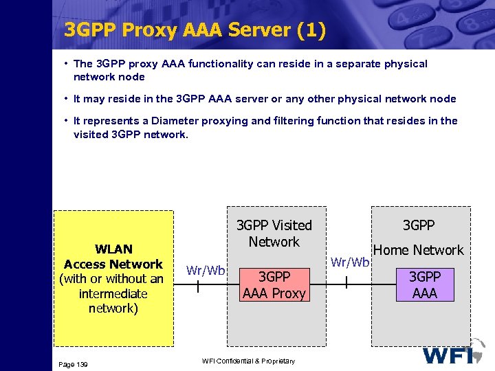 3 GPP Proxy AAA Server (1) • The 3 GPP proxy AAA functionality can reside in a separate physical network node • It may reside in the 3 GPP AAA server or any other physical network node • It represents a Diameter proxying and filtering function that resides in the visited 3 GPP network. WLAN Access Network (with or without an intermediate network) Page 139 3 GPP Visited Network Wr/Wb 3 GPP AAA Proxy WFI Confidential & Proprietary 3 GPP Wr/Wb Home Network 3 GPP AAA
 3 GPP Proxy AAA Server (2) • The 3 GPP proxy AAA functions include: 3 Relaying the AAA information between WLAN and the 3 GPP AAA Server 3 Enforcing policies derived from roaming agreements between 3 GPP operators and between WLAN operator and 3 GPP operator 3 Reporting charging/accounting information to local Charging Collection Function(CCF)/Charging Gateway (CGw) for roaming users 3 Service termination (O&M initiated termination from visited NW operator) 3 Receiving authorisation information (Subscriber information) 3 Forwarding authorisation information to WLAN 3 Rejection of authorisation according to local policy Page 140 WFI Confidential & Proprietary
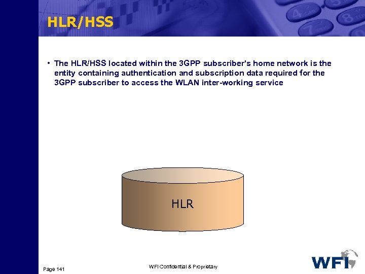 HLR/HSS • The HLR/HSS located within the 3 GPP subscriber's home network is the entity containing authentication and subscription data required for the 3 GPP subscriber to access the WLAN inter-working service HLR Page 141 WFI Confidential & Proprietary
 Packet Data Gateway (1) • The Packet Data Gateway is a node via which packet data networks are connected to 3 GPP inter-working WLAN Access Network (with or without an intermediate network) Page 142 Wn Wn 3 GPP Home Network Border Gateway Packet Data Gateway 3 GPP Visited Network 3 GPP Home Network Border Gateway Packet Data Gateway WFI Confidential & Proprietary Wi Wi
 Packet Data Gateway (2) • The location of Packet Data Gateway may be different for each specific service accessed WLAN. 3 For some WLAN connections no Packet Data Gateway is used, 3 For some accessed services the Packet Data Gateway may be in the home network and 3 For some accessed services it may locate in the visited Network Page 143 WFI Confidential & Proprietary
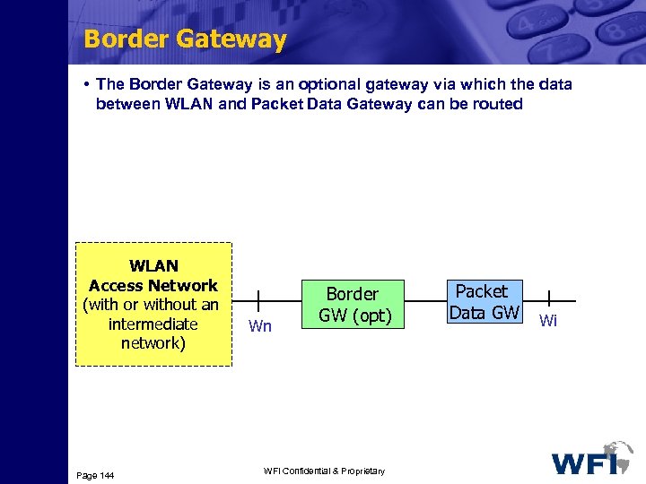 Border Gateway • The Border Gateway is an optional gateway via which the data between WLAN and Packet Data Gateway can be routed WLAN Access Network (with or without an intermediate network) Page 144 Wn Border GW (opt) WFI Confidential & Proprietary Packet Data GW Wi
 Reference Points (Interfaces) • The interfaces between the network elements are referred to in the specifications as reference points. They are: 3 Wr: Connects WLAN AN to the 3 GGP AAA server 3 Wx: Located between the 3 GPP AAA server and the HSS 3 D’/Gr’: Located between the 3 GPP AAA server and the HLR 3 Wb: Located between the WLAN AN and the 3 GPP network 3 Wo: Used by a 3 GPP server to communicate with the OCS 3 Wf: Located between the 3 GPP AAA server and the CCF/CGw 3 Wn: Tunnels WLAN user data towards the 3 GPP system 3 Wi: Connects the PDGW and a Packet Data Network Page 145 WFI Confidential & Proprietary
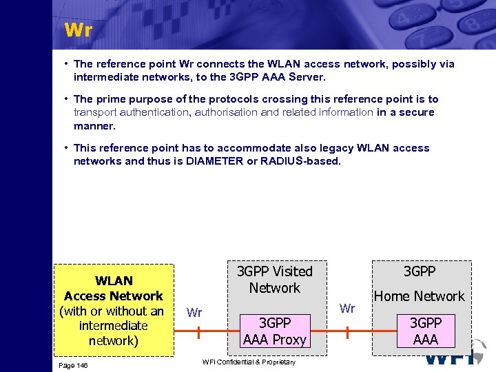 Wr • The reference point Wr connects the WLAN access network, possibly via intermediate networks, to the 3 GPP AAA Server. • The prime purpose of the protocols crossing this reference point is to transport authentication, authorisation and related information in a secure manner. • This reference point has to accommodate also legacy WLAN access networks and thus is DIAMETER or RADIUS-based. WLAN Access Network (with or without an intermediate network) Page 146 3 GPP Visited Network Wr 3 GPP AAA Proxy WFI Confidential & Proprietary 3 GPP Wr Home Network 3 GPP AAA
 Wr Functionality • The functionality of the Wr reference point (interface) is to transport RADIUS/DIAMETER frames: 3 Carrying data for authentication signalling between a WLAN UE and a 3 GPP AAA Server 3 Carrying data for authorisation signalling between a WLAN AN and a 3 GPP AAA server 3 Carrying keying data for the purpose of radio interface integrity protection and encryption 3 Used for purging a user from the WLAN access for immediate service termination Page 147 WFI Confidential & Proprietary
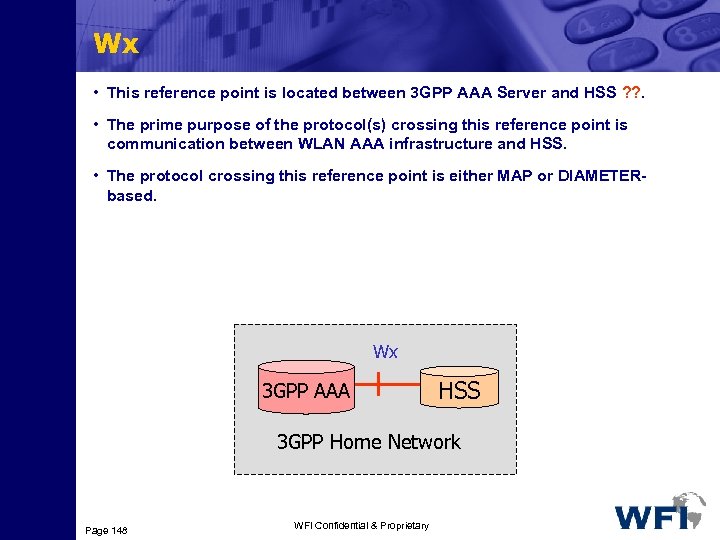 Wx • This reference point is located between 3 GPP AAA Server and HSS ? ? . • The prime purpose of the protocol(s) crossing this reference point is communication between WLAN AAA infrastructure and HSS. • The protocol crossing this reference point is either MAP or DIAMETERbased. Wx 3 GPP AAA HSS 3 GPP Home Network Page 148 WFI Confidential & Proprietary
 Wx Functionality • The functionality of the reference point is to enable: 3 Retrieval of authentication vectors, e. g. for USIM authentication, from HSS. 3 Retrieval of WLAN access-related subscriber information (profile) from HSS 3 Registration of the 3 GPP AAA Server of an authorised WLAN user in the HSS. 3 Indication of change of subscriber profile within HSS (e. g indication for the purpose of service termination). Page 149 WFI Confidential & Proprietary
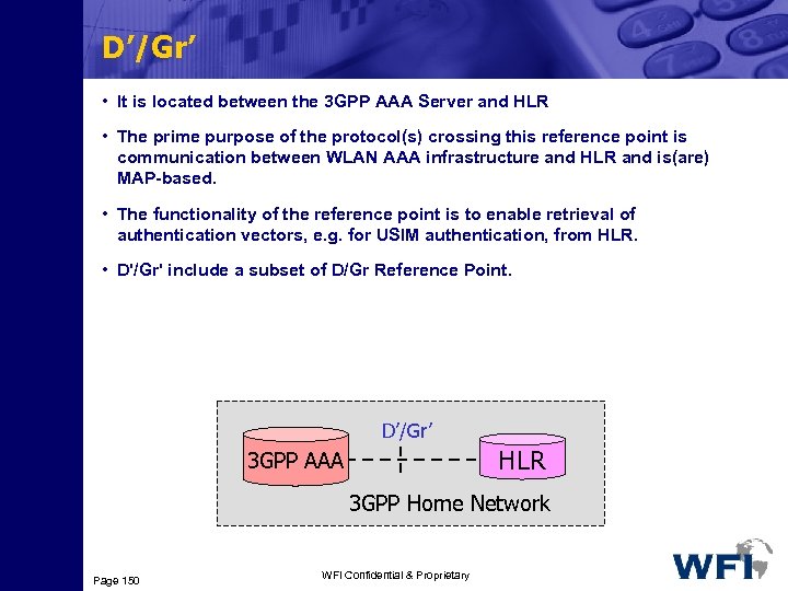 D’/Gr’ • It is located between the 3 GPP AAA Server and HLR • The prime purpose of the protocol(s) crossing this reference point is communication between WLAN AAA infrastructure and HLR and is(are) MAP-based. • The functionality of the reference point is to enable retrieval of authentication vectors, e. g. for USIM authentication, from HLR. • D'/Gr' include a subset of D/Gr Reference Point. D’/Gr’ HLR 3 GPP AAA 3 GPP Home Network Page 150 WFI Confidential & Proprietary
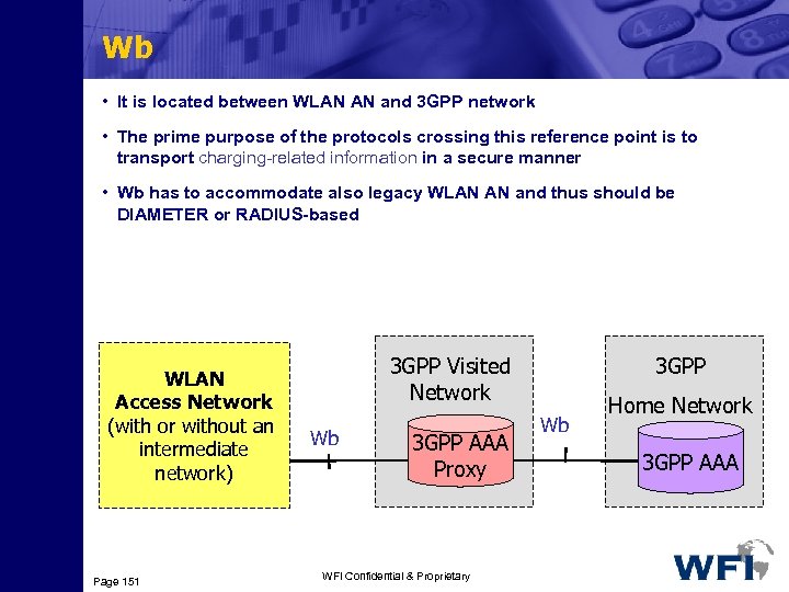 Wb • It is located between WLAN AN and 3 GPP network • The prime purpose of the protocols crossing this reference point is to transport charging-related information in a secure manner • Wb has to accommodate also legacy WLAN AN and thus should be DIAMETER or RADIUS-based WLAN Access Network (with or without an intermediate network) Page 151 3 GPP Visited Network Wb 3 GPP AAA Proxy WFI Confidential & Proprietary 3 GPP Wb Home Network 3 GPP AAA
 Wb Functionality • The functionality of the reference point is to transport RADIUS/DIAMETER frames with charging signalling per each WLAN user • The fact that a user is offline or online charged by his 3 GPP subscription provider is transparent for the WLAN AN and thus for the Wb reference point 3 This will minimise the requirements put on the WLAN Access Network. It will also protect the confidentiality of the subscribers charging status • However for online charged users the interval to deliver accounting information from WLAN AN over Wb reference point may typically be set to a smaller value than for offline charged users. Page 152 WFI Confidential & Proprietary
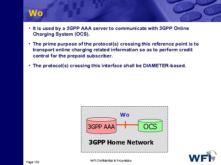 Wo • It is used by a 3 GPP AAA server to communicate with 3 GPP Online Charging System (OCS). • The prime purpose of the protocol(s) crossing this reference point is to transport online charging related information so as to perform credit control for the prepaid subscriber. • The protocol(s) crossing this interface shall be DIAMETER-based. Wo 3 GPP AAA OCS 3 GPP Home Network Page 153 WFI Confidential & Proprietary
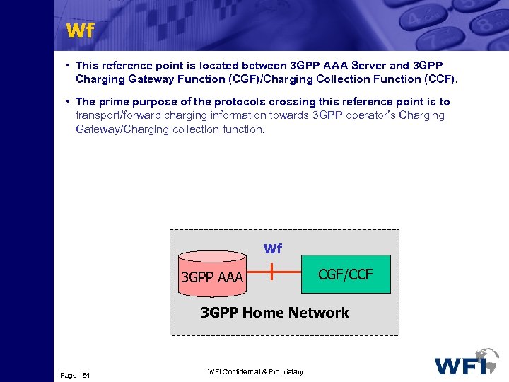 Wf • This reference point is located between 3 GPP AAA Server and 3 GPP Charging Gateway Function (CGF)/Charging Collection Function (CCF). • The prime purpose of the protocols crossing this reference point is to transport/forward charging information towards 3 GPP operator’s Charging Gateway/Charging collection function. Wf 3 GPP AAA CGF/CCF 3 GPP Home Network Page 154 WFI Confidential & Proprietary
 Wf Functionality • The information forwarded to Charging Gateway/Charging collection function is typically used for 3 generating bills for offline charged subscribers by the subscribers’ home operator 3 Calculation of inter-operator clearing charging from all roaming users. This inter operator clearing is used to settle the payments between visited and home network operator and/or between home/visited network and WLAN. • The protocol(s) crossing this interface is (are) DIAMETER-based. • The functionality of the reference point is to transport WLAN access-related charging data per each WLAN user Page 155 WFI Confidential & Proprietary
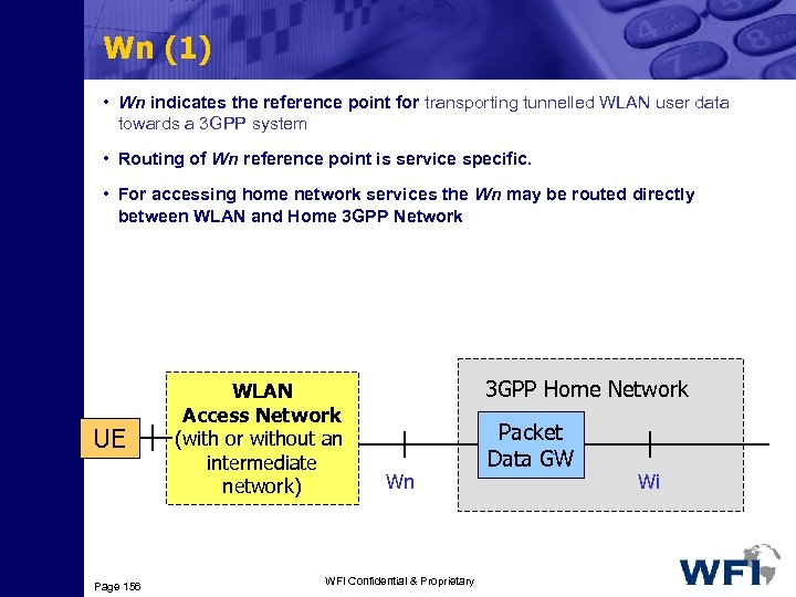 Wn (1) • Wn indicates the reference point for transporting tunnelled WLAN user data towards a 3 GPP system • Routing of Wn reference point is service specific. • For accessing home network services the Wn may be routed directly between WLAN and Home 3 GPP Network UE Page 156 WLAN Access Network (with or without an intermediate network) 3 GPP Home Network Wn WFI Confidential & Proprietary Packet Data GW Wi
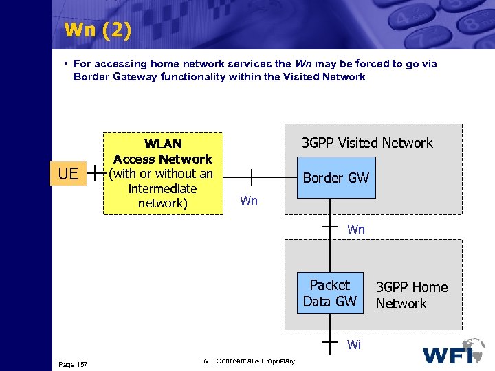 Wn (2) • For accessing home network services the Wn may be forced to go via Border Gateway functionality within the Visited Network UE WLAN Access Network (with or without an intermediate network) 3 GPP Visited Network Border GW Wn Wn Packet Data GW Wi Page 157 WFI Confidential & Proprietary 3 GPP Home Network
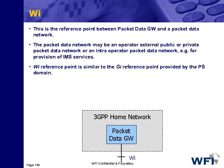 Wi • This is the reference point between Packet Data GW and a packet data network. • The packet data network may be an operator external public or private packet data network or an intra operator packet data network, e. g. for provision of IMS services. • Wi reference point is similar to the Gi reference point provided by the PS domain. 3 GPP Home Network Packet Data GW Wi Page 158 WFI Confidential & Proprietary
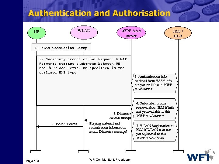 Authentication and Authorisation WLAN UE 3 GPP AAA server HSS / HLR 1. WLAN Connection Setup 2. Necessary amount of EAP Request & EAP. 2. EAP Request / Identity Response message exchanges between UE 3. EAP AAA Server as specified in the and 3 GPP Response / Identity [User ID in NAI utilised EAP type format] 3. Authentication info retrieval from HSSif info not yet available in 3 GPP AAA server 5. Diameter Access Accept 6. EAP / Success Page 159 [Keying material and authorisation information within Diameter message] WFI Confidential & Proprietary 4. Subscriber profile retrieval from HSS if info not yet available in this 3 GPP AAA server. retrieval from HSS if info 7. WLAN Registration to not yet available in 3 GPP HSS if WLAN user not AAA server yet registered to this 3 GPP AAA Server
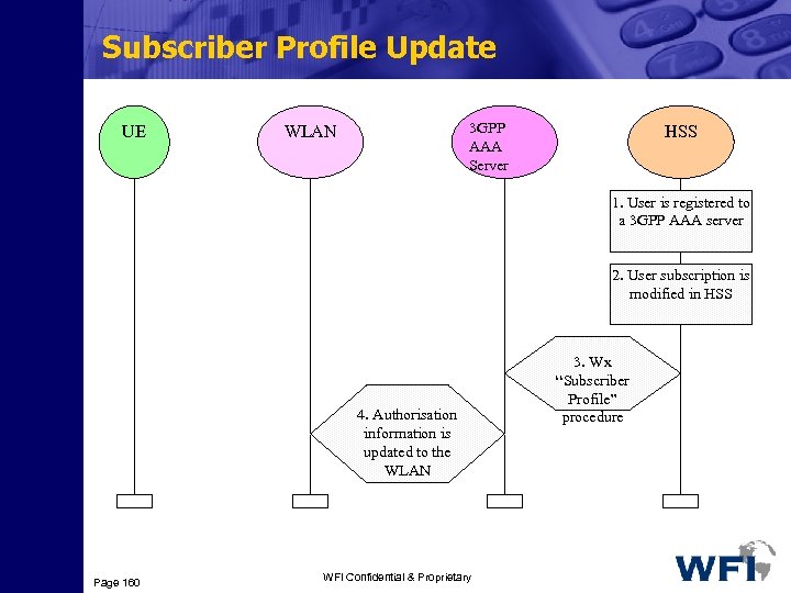 Subscriber Profile Update UE 3 GPP AAA Server WLAN HSS 1. User is registered to a 3 GPP AAA server 2. User subscription is modified in HSS 4. Authorisation information is updated to the WLAN Page 160 WFI Confidential & Proprietary 3. Wx “Subscriber Profile” procedure
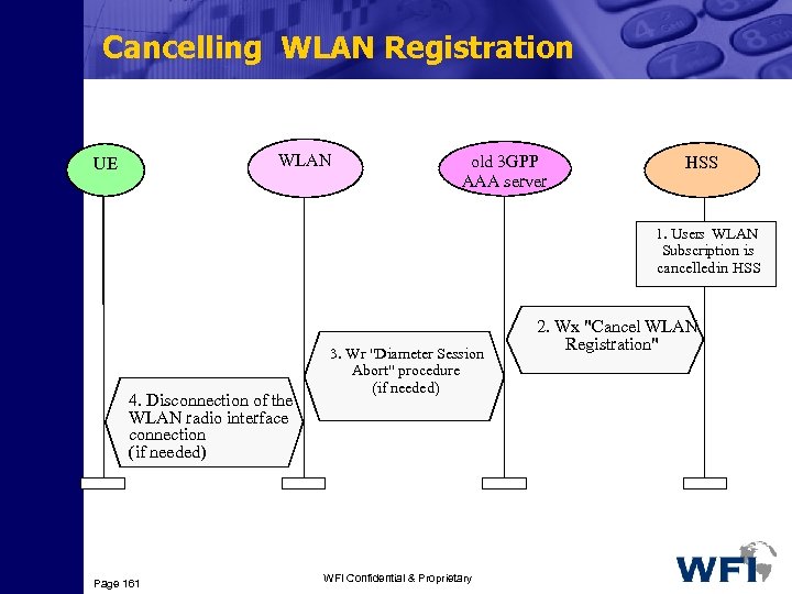 Cancelling WLAN Registration WLAN UE old 3 GPP AAA server HSS 1. Users WLAN Subscription is cancelled in HSS 4. Disconnection of the WLAN radio interface connection (if needed) Page 161 3. Wr "Diameter Session Abort" procedure (if needed) WFI Confidential & Proprietary 2. Wx "Cancel WLAN Registration"
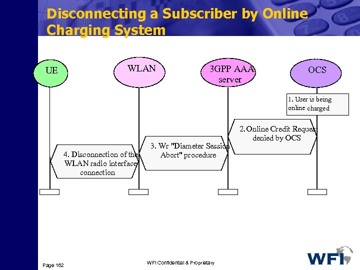 Disconnecting a Subscriber by Online Charging System WLAN UE 3 GPP AAA server OCS 1. User is being online charged 4. Disconnection of the WLAN radio interface connection Page 162 3. Wr "Diameter Session Abort" procedure WFI Confidential & Proprietary 2. Online Credit Request denied by OCS
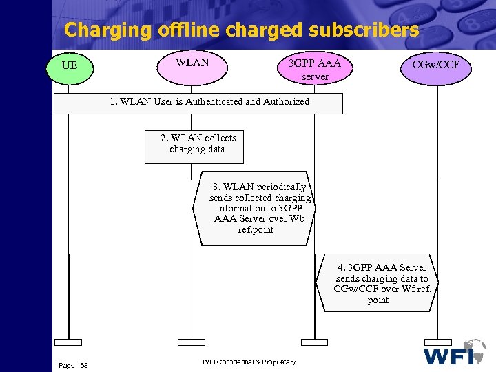 Charging offline charged subscribers UE WLAN 3 GPP AAA server CGw/CCF 1. WLAN User is Authenticated and Authorized 2. WLAN collects charging data 3. WLAN periodically sends collected charging Information to 3 GPP AAA Server over Wb ref. point 4. 3 GPP AAA Server sends charging data to CGw/CCF over Wf ref. point Page 163 WFI Confidential & Proprietary
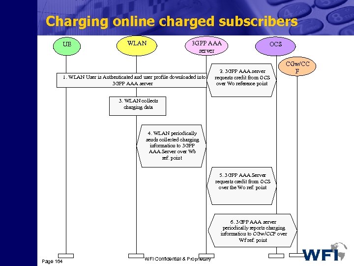 Charging online charged subscribers UE WLAN 3 GPP AAA server 1. WLAN User is Authenticated and user profile downloaded into 3 GPP AAA server OCS 2. 3 GPP AAA server requests credit from OCS over Wo refere point nce CGw/CC F 3. WLAN collects charging data 4. WLAN periodically sends collected charging information to 3 GPP AAA Server over Wb ref. point 5. 3 GPP AAA Server requests credit from OCS over the Wo ref. point 6. 3 GPP AAA server periodically reports charging information to CGw/CCF over Wf ref. point Page 164 WFI Confidential & Proprietary


