98a40d3050fac46fff945489ae591b32.ppt
- Количество слайдов: 36


Megawatt targets for Neutrino Super-Beams RAL High Power Targets Group: Chris Densham, Tristan Davenne, Mike Fitton, Peter Loveridge, Matt Rooney, Otto Caretta LBNE study in collaboration with : Patrick Hurh, Bob Zwaska, James Hylen, Sam Childress, Vaia Papadimitriou (Fermilab) + T 2 K Beam Group + LAGUNA/LBNO/CN 2 PY Study Group

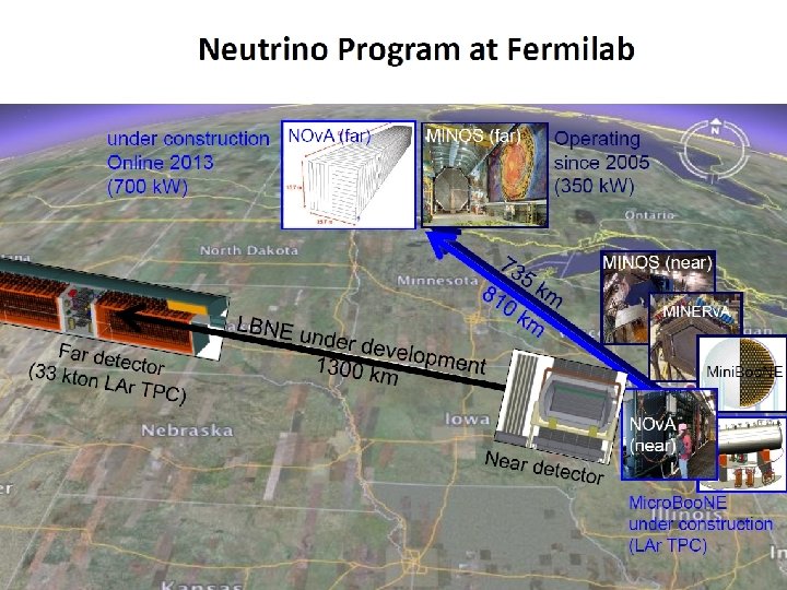
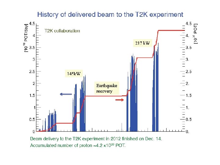
‘Conventional’ neutrino beams: where we are Fermilab Nu. MI/NOv. A JPARC T 2 K CERN CNGS Beam energy 120 Ge. V 30 Ge. V 400 Ge. V Beam cycle 2. 2 s 2. 1 s 6 s Spill length 10 µs 4. 2 µs 2 x 10. 5 µs Design beam power 400 k. W 750 k. W Maximum beam power to date 375 k. W 230 k. W 311 k. W (448 k. W over 30 s) Beam size (rms) 1. 1 mm 4. 2 mm 0. 5 mm Physics νµ disappearance νµ -> νe appearance, νµ disappearance νµ -> ντ appearance First beam 2005 2009 2006
 JPARC T 2")
Neutrino ‘Superbeams’: where we want to go Fermilab LBNE (/Project X) JPARC T 2 K Long term plan (2018 -) CERN CN 2 PY/LBNO (Phase 2) Design beam power 2. 3 MW 3. 2 MW Beam energy 120 Ge. V 50 (70)Ge. V Rep rate 0. 75 Hz 1. 33 Hz Beam sigma (range) 1. 5 – 3. 5 mm 4. 2 mm Heat load in: C Be 10. 5 – 23. 1 k. W Ti pebble bed ~100 k. W

LBNE Overview PASI 2013 WG 1 - Nu Superbeam 4/4/13 5

LBNE Target Facility – for 2. 3 MW operation Decay Pipe concrete shielding (5. 5 m) Work Cell Decay Pipe: Length - 200 m Radius – 2 m Baffle/Targe t Carrier Target Chase: 1. 6 m/1. 4 m wide, 24. 3 m long PASI 2013 WG 1 - Nu Superbeam 4/4/13 Geomembrane barrier system to keep groundwater out of decay region (Target Chase & Absorber Hall also) 6

T 2 K Target Station for 4 MW 27 m Y. Yamada 34 m 40 ton crane 14 m Assembly stage for horns Ground level Machine room Service pit 22 m Concrete blocks Final focus Beam window Iron structure /Helium vessel Iron shield Storage for radioactive material DV partition Iron shield Decay volume Concrete structure Baffle Target & 1 st horn 2 nd horn 3 rd horn

T 2 K Target and horn

T 2 K: Plans for 8 Ge. V Booster Ring for 2 -3 MW Tadashi Koseki (KEK)
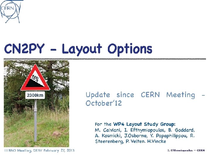
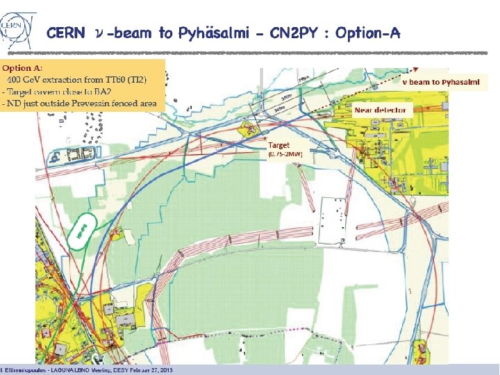

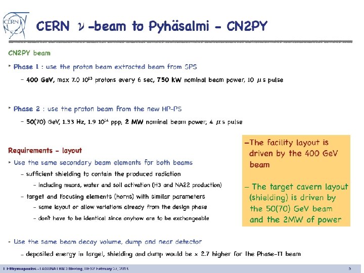
Preliminary Concept for CN 2 PY • Keep as many buildings as possible at the surface to keep construction costs down – Must have a shaft to access the horns and targets – Power supplies (or transformers) must be underground, close to the beamline – The pump house may also be underground, depending on the acceptable pressure drop Drawings not to scale: number and layout of horns will be different in practice, as will beamline dimensions Dan Wilcox
 Long enough ( 2 interaction lengths ) to interact most")
Target Basics (J. Hylen) Long enough ( 2 interaction lengths ) to interact most protons Dense enough that 2 lint fits in focusing system depth-of-field Radius: Rtarget = 2. 3 to 3 Rbeam (minimize gaussian tails missing target) Narrow enough that pions exit the sides without re-absorption (but for high Eproton and low En, secondary shower can help) High pion yield ( but to first order, n flux a beam power ) Radiation hard Withstand high temperature High strength (withstand stress from fast beam pulse) Low density (less energy deposition density, hence less stress; don’t reabsorb pions) Low d. E/dx (but not much variation between materials) High heat capacity (less stress induced by the d. E/dx) Low thermal expansion coefficient (less stress induced by the d. E/dx) Low modulus of elasticity (less stiff material does not build up stress) Reasonable heat conductivity Reasonable electrical conductivity ( monitor target by charge ejection) CNGS, Nu. MI, T 2 K all using graphite 15

Existing target technologies Nu. MI/NOv. A CNGS T 2 K Target material Graphite: POCO ZXF-5 Q Graphite and Carbon-carbon Graphite: IG 430 Target arrangement Subdivided subdivided monolithic Cooling Water (forced convection) Helium (natural convection) Helium (forced convection) • Only possible for low deposited heat loads • Heat transfer • Radiation damage • High helium volumetric flow rate (and high pressure or high pressure drops) Limitations for • Radiation damage higher power • Water hammer, cavitation operation • Hydrogen + tritium + water activation

Limitations of target technologies Flowing or rotating targets Segmented Peripherally cooled monolith

Ashes to ashes, dust to dust. . . Effect of proton beams on some graphite targets LAMPF fluence 10^22 p/cm 2 BNL tests: fluence ~10^21 p/cm 2 PSI fluence 10^22 p/cm 2

Physics vs Engineering Optimisation ? Target and Beam Dimensions • For pion yield – smaller is better – Maximum production and minimum absorption (shown by Fo. M) • For target lifetime – bigger is better – Lower power density – lower temperatures, lower stresses – Lower radiation damage density • For integrated neutrino flux, need to take both neutrino flux and lifetime factors into account – Want to make an assessment of trade off between target lifetime vs beam and target dimensions – Answer will depend on Target Station engineering (time to change over target and horn systems)

Target configurations considered for Superbeams 1. LBNE at Fermilab • • Integral target and horn inner conductor – – Solid Be rod water spray cooled Separate target installed inside bore of horn inner conductor – – – Graphite, water cooled (IHEP study (baseline)) Be: subdivided in z, water cooled Be: spheres, helium cooled 2. EUROnu Super. Beam using high power SPL at CERN 4 -horn system (4 x 12. 5 Hz) • • ‘Pencil’ shaped beryllium rod ‘Packed bed’ of titanium beads Integral target and horn inner conductor (Graphite excluded due to radiation damage concerns)

LBNE Beryllium rod target: Stress-Waves Effect of beam spill time on the peak dynamic stress in the target

LBNE Beryllium rod target: Stress-Waves • “static” stress component is due to thermal gradients – Independent of spill time Effect of beam spill time on the peak dynamic stress in the target

LBNE Beryllium rod target: Stress-Waves • “static” stress component is due to thermal gradients – Independent of spill time • “dynamic” stress component is due to stress waves – Spill time dependent Effect of beam spill time on the peak dynamic stress in the target

LBNE Beryllium rod target: Stress-Waves • “static” stress component is due to thermal gradients – Independent of spill time • “dynamic” stress component is due to stress waves – Spill time dependent • Tspill > Radial period – Radial stress waves are not significant Effect of beam spill time on the peak dynamic stress in the target

LBNE Beryllium rod target: Stress-Waves • “static” stress component is due to thermal gradients – Independent of spill time • “dynamic” stress component is due to stress waves – Spill time dependent • Tspill > Radial period • Tspill < Longitudinal period – Radial stress waves are not significant – Longitudinal stress waves are important! Effect of beam spill time on the peak dynamic stress in the target
")
Pressurised helium cooled concept (2 MW)
 Heat transfer coefficient Otto Caretta & Tristan Davenne")
Pressurised helium cooled concept (2 MW) Heat transfer coefficient Otto Caretta & Tristan Davenne Mid-plane temperatures
 Beryllium sphere diameter Beam sigma Helium mass flow")
Pressurised helium cooled concept (2 MW) Beryllium sphere diameter Beam sigma Helium mass flow rate Inlet helium pressure Outlet helium pressure Inlet velocity Maximum velocity Total heat load Maximum beryllium temperature Helium temperature rise, DT (Tin-Tout) Otto Caretta & Tristan Davenne 13 mm 2. 2 mm 17 g/s 11. 1 bar 10 bar 40 m/s 185 m/s 9. 4 k. W 178 C 106 C

Conclusions: ‘Divide and Rule’ for increased power Dividing material is favoured since: • Better heat transfer • Lower static thermal stresses • Lower dynamic stresses from intense beam pulses Helium cooling is favoured (cf water) since: • No ‘water hammer’ or cavitation effects from pulsed beams • Lower coolant activation, no radiolysis • Negligible pion absorption – coolant can be within beam footprint • For graphite, higher temperatures anneal radiation damage Static, low-Z target concepts proposed

Packed Bed Target Concept Solution Packed bed cannister in symmetrical transverse flow configuration Titanium alloy cannister containing packed bed of titanium alloy spheres Cannister perforated with elipitical holes graded in size along length T. Davenne Model Parameters Proton Beam Energy = 4. 5 Ge. V Beam sigma = 4 mm Packed Bed radius = 12 mm Packed Bed Length = 780 mm Packed Bed sphere diameter = 3 mm Packed Bed sphere material : Titanium Alloy Coolant = Helium at 10 bar pressure

Particle bed advantages • • • Large surface area for heat transfer Coolant can pass close to maximum energy deposition High heat transfer coefficients Low quasi static thermal stress Low dynamic stress (for oscillation period <<beam spill time) . . . and challenges • High pressure drops, particularly for long thin superbeam target geometry • Need to limit gas pressure for beam windows • Transverse flow reduces pressure drops – but • Difficult to get uniform temperatures and dimensional stability of container
 100 m/s Velocity vectors showing inlet")
Packed Bed Model (FLUKA + CFX v 13) 100 m/s Velocity vectors showing inlet and outlet channels and entry and exit from packed bed Streamlines in packed bed Packed bed modelled as a porous domain Permeability and loss coefficients calculated from Ergun equation (dependant on sphere size) Overall heat transfer coefficient accounts for sphere size, material thermal conductivity and forced convection with helium Interfacial surface area depends on sphere size Acts as a natural diffuser flow spreads through target easily T. Davenne

Packed Bed temperatures Titanium temperature contours Maximum titanium temperature = 946 K =673°C (N. B. Melting temp =1668°C) Outer Can Surface Temp Almost Symmetric Temperature contours Maximum surface Temperature = 426 K = 153°C NB windows not included in model yet - Double skin Be should withstand both heat and pressure loads

Future LBNE Collaborative Opportunities? • Further prototyping on LBNE 700 k. W target (Be or Ti outer tube replacing Al) – Eventual manufacture of spare target? – Requires good design/analysis and manufacturing capabilities • Pre-conceptual scoping of 2. 3 MW target (graphite or Be) – Requires good design/analysis capabilities • Conceptual design and prototyping of LBNE beam windows: – Especially for 2+ MW beam power – Possibility of Decay Pipe windows (challenge even at 700 k. W) – Requires good design/analysis capabilities • Hadron Monitor design and prototyping (eventual manufacture? ) – Need new radiation hardened version for LBNE – Requires good design/analysis and manufacturing capabilities PASI 2013 WG 1 - Nu Superbeam 4/4/13 34

Hadron Monitor • • Measures position and intensity of secondary particles at the end of the decay pipe (in absorber shield pile) LBNE has shorter decay pipe than Nu. MI • More heating • More radiation damage • 5 x better resolution • • • Current conceptual design is parallel plate ionization chambers with low pressure helium Used during beam/target/horn alignment & diagnostic scans and monitoring degradation of target material Good project to take from design to construction PASI 2013 WG 1 - Nu Superbeam Nu. MI Hadron Monitor being calibrated at University of 35 Texas 4/4/13

Target collaboration for the first Neutrino Superbeam • • Whichever facility – LBNE/LBNO/T 2 HK – is first to be approved for construction/upgrade to operate in the MW region, there will be little time to develop a target system There is very significant commonality/synergy between the target/horn system and target station for all proposed facilities Now is a good time to get ready by collaborating over the necessary research and development Common challenges/areas for collaboration: – Target station design (T 2 K already constructed for 3 -4 MW) – Beam window – Low Z target, 1 -3 λ long • heat transfer, stress waves, lifetime - radiation damage effects, performance optimisation – Integration of target with horn to capture low energy pions – Horn – lifetime, radiation damage effects – Instrumentation – OTR, beam
98a40d3050fac46fff945489ae591b32.ppt