1bb2a265a7ef0e40a5aee2297688801a.ppt
- Количество слайдов: 148


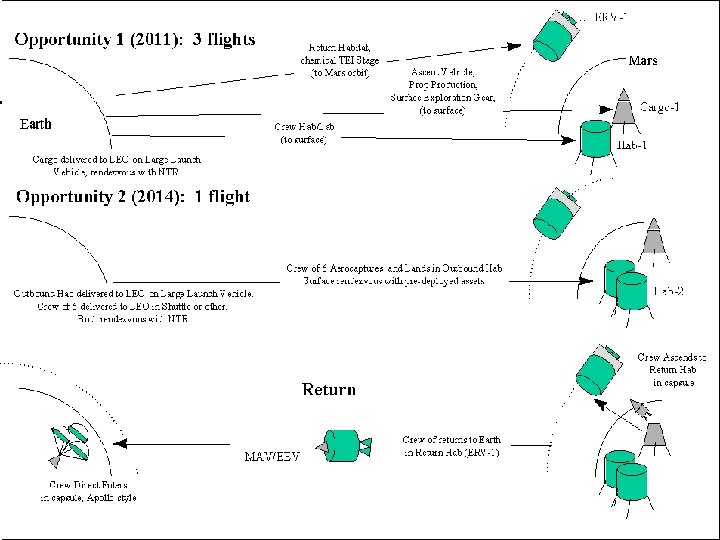
Mars or Bust Preliminary Design Review 12/8/03

Mission Description • Based on the Design Reference Mission from NASA (Hoffman and Kaplan, 1997; Drake, 1998) • Modified to narrow scope of project

Key Assumptions for Design • Only first uncrewed Habitat • Focusing on surface operations – Launch, transit, Mars entry not designed • Interfaces with external equipment – Rovers, power supply, ISRU unit • Crew will use Habitat on arrival

Overall Project Goal • Establish a Martian Habitat capable of supporting humans

Overall - Level 1 Requirements • Support crew of 6 • Support 600 day stay without resupply • Maintain health and safety of crew • Minimize dependency on Earth

Launch and Deployment Requirements • 80 metric ton launch vehicle • Recommended Total Habitat Mass < 34, 000 kg (includes payload) • Deploys 2 years before first crew • Land, deploy, operate, maintain all systems • Setup and check-out before crew arrives • Standby mode for 10 months between crews • Operational lifetime of greater than 15 years

Redundancy Requirements • • • Mission critical: 2 -level redundancy Life critical: 3 -level redundancy Auto fault detection and correction Modular Easily repairable Electronic and mechanical equipment – Highly autonomous – Self-maintained or crew maintained – If possible self-repairing • All systems in Habitat must have low failure rates

Operations Requirements • Gather information about Mars • Ease of learning – System similarity – Common software and hardware • Real time science activity planning • Integrate In-Situ Resource Utilization System

Mission Architecture • • • Systems Engineering and Integration Structures Command, Control, and Communications (C 3) Power Distribution and Allocation Environment Control and Life Support Systems (ECLSS) Mission Operations and Crew Accommodations Automation and Robotic Interfaces Extra Vehicular Activity Systems (EVAS) Thermal Control In-situ Resource Utilization Unit (ISRU) and Mars Environment

Organizational Chart Project Manager Systems Engineering and Integration Mission Operations Crew Accommodations Structures CCC Power ECLSS Robotics and Automation EVAS Thermal ISRU

Systems Engineering and Integration Team • Primary: – Juniper Jairala – Tim Lloyd – Tyman Stephens • Support: – Meridee Silbaugh – Jeff Fehring – Keith Morris

Systems Engineering and Integration Responsibilities • Establish habitat system requirements • Delegate top-level subsystem requirements • Review and reconcile all subsystem design specifications • Ensure that all habitat subsystem requirements are met • Ensure proper subsystem interfaces


DRM Mass Recommendations Subsystem Structure Power ECLSS Thermal Crew Accommodations C 3 EVAS Total Mass Estimate [kg] 20, 744 3250 4661 550 5000 320 1629 34, 000
 Primary • Heather Chluda Support • Keagan")
Mars Environment and In-Situ Resource Utilization (ISRU) Primary • Heather Chluda Support • Keagan Rowley • Keric Hill

Mars Environment Summary • Responsible for collecting data on the Mars Environment • Provides a consistent data set on the Mars Environment for the Habitat design group to use. • Thermal, Radiation, Pressure, Atmosphere, Wind, etc.

Mars Environment Characteristics The Habitat will encounter a wide range of environment characteristics during its surface stay on Mars

Temperatures • Diurnal variation at Viking Lander sites • Seasonal variation: -107 to -18°C winter to summer lows

Radiation • GCR BFO dose equivalent for solar min and max vs. altitude SPE Dose: 5 c. Sv/yr GCR BFO Dose: 22. 3 c. Sv/yr GCR Skin Dose: 24. 7 c. Sv/yr LEO BFO Limit: 50 c. Sv/yr LEO Skin Limit: 300 c. Sv/yr
 95. 32 Nitrogen 2. 7")
Martian Constituents Atmospheric Composition Gas Carbon Dioxide Abundance (%) 95. 32 Nitrogen 2. 7 Argon 1. 6 Oxygen 0. 13 Carbon Monoxide 0. 08 Water Vapor 0. 03 Neon 0. 00025 Krypton 0. 00003 Xenon 0. 000008 Ozone 0. 000004

Future Considerations • More detailed temperature and radiation data for specific landing site • Determination of topography of landing site and exploration area • More detailed information from upcoming Mars missions

ISRU Subsystem Summary • Responsible for interface between habitat and ISRU plant • ISRU will provide additional oxygen, nitrogen, and water for habitat use • Non-critical system, demonstration for future mission use

ISRU Level 2 Requirements • Provide additional nitrogen, water and oxygen • Byproducts of propellant production used as backup oxygen, nitrogen, and water • Storage tanks and pipes for the ISRU shall tolerate leaks within limits • Propellant production shall be automated • Acceptable temperatures shall be maintained in storage tanks and piping • Storage interfaces must be compatible with habitat • Pumping systems shall have adequate power to transport oxygen, nitrogen and water to the habitat • Piping and storage tanks must be shielded from Mars Environment • Connections to storage tanks and ISRU tanks must be performed using robots or humans

ISRU I/O Diagram

ISRU Functional Diagram
 # Total Mass (kg) Power (k. W)")
ISRU Interface Technologies Component Add. Mass (kg) # Total Mass (kg) Power (k. W) Total Volume (m 3) Water Pump 1 70. 50 Oxygen Pump 1 0. 94 1. 50 Nitrogen Pump 1 0. 94 1. 50 Water Pipe 1 70. 00 80. 00 0. 65 Oxygen Pipe 1 70. 00 0. 65 Nitrogen Pipe 1 70. 00 0. 65 Hydrogen Pipe 1 70. 00 1. 50 0. 65 Valves and Connections 9 42. 00 5. 00 0. 00 404. 38 80. 00 2. 60 Grand Totals 10. 00

ISRU Requirement Verification

ISRU Plant Trade Study ISRU Plant Type W/kg of Products Advantages product Zirconia Electrolysis 1710 O 2 Simple operation Many fragile tubes required Sabatier Electrolysis 307 CH 4 O 2 (H 2 O) High Isp Requires H 2 Cryogenic Storage Non-ideal mixture ratio RWGS Methane 307 CH 4 O 2 (H 2 O) Ideal mixture ratio Requires H 2 Cryogenic Storage RWGS Ethylene 120 C 2 H 4 O 2 (H 2 O) Non-cryogenic High Isp Requires ½ x H 2 RWGS Methanol 120 CH 3 OH O 2 (H 2 O) Non-cryogenic Requires 2 x H 2 Low flame Temp. Lower Isp Disadvantages

Future Considerations • Radiation shielding effects of Martian soil – Soil safe haven shelter designs • Mass benefits of using ISRU plant for consumables on future missions

Structures Subsystem Team • Primary: – Jeff Fehring – Eric Schleicher • Support: – Jen Uchida – Sam Baker

Structures Subsystem • • Overall layout Volume allocation Pressurized volume Physically support all subsystems Radiation shielding Micro-meteoroid shielding Withstand all loading environments

Level 2 Requirements • Fit within the dynamic envelope of the launch vehicle – Launch Shroud Diameter = 7. 5 m – Length = 27. 7 m • Structurally sound in all load environments – Acceleration – Vibration – Pressure • • Easily repairable Stably support all other systems Interface with other systems Structures Mass < 20744 kg

Structures I/O Diagram

Structures Overview • • • Pressure Shell Trusses Leg Supports Chassis and Wheels Radiation Shielding – Safe haven • Supports for other subsystem components • Other Structures – – Hatches Vents Windows Seals

Overall Layout
 Structure 150. 00 ECLSS 65. 00 Thermal 40.")
Volume Allocation Subsystem Volume (m 3) Structure 150. 00 ECLSS 65. 00 Thermal 40. 00 EVAS 40. 00 Robotics 15. 00 Power 30. 00 ISRU Interface 4. 00 CCC 5. 00 Crew Accommodations Empty 50. 00 216. 75 Totals 615. 75216

Pressure Shell • • Assume aluminum shell Assume a hollow cylinder, radius 3. 5 m Thickness t = Pr/fy = 1. 7 mm for 10. 2 psi Assume pressure shell holds 34 tonnes Assume launch forces similar to Atlas V Minimum thickness = 3 mm for stability Internal trusses carry part of the load

Supports • Assume 6 hollow tube leg supports • Support entire mass of Habitat on Mars – Mars gravity = 3. 758 m/s 2 – Weight = 128 k. N • Maintain stability in Martian wind storm – Maximum wind speed = 127 kph – Maximum wind force = 17 k. N • Maximum compressive force = 54. 5 k. N/leg • Dimensions of leg to minimize mass: – Length = 2 m – Radius = 13 cm – Thickness = 1 mm

Mass, Power, and Volume Estimates

Requirements Verification

Future Considerations • Design for launch loads from Magnum vehicle • Optimize truss structure • Fully design supports for all components

Power Distribution and Allocation Subsystem Team • Primary: – Tom White – Jen Uchida • Support: – Nancy Kungsakawin – Eric Dekruif

Power • Interface with the nuclear power source and other external equipment • Safely manage and distribute power throughout Martian habitat

Level 2 Requirements • • • Supply sufficient power with 3 -level redundancy Supply power while reactors are being put online Transfer power from reactor to habitat Distribute power on a multi-bus system Provide storage and interfaces for rovers/EVA suits Interface with transit vehicle power sources Regulate voltage to a usable level Include a fault protection system Provide an emergency power cutoff Mass must not exceed 3249 kg (including in-transit power)

Input/Output • Input: – Power from reactor – Info/control from CCC • Output: – Power to habitat – Heat to thermal Habitat Thermal All Subsystems Heat Power Cargo Lander CCC Info/control EPDS Power Info/control PS Power

Mars Surface Power Allocation • Allotted ~25 k. W • Potential to use power allocated to other systems (DRM)

Overview of System Power Profile

System Schematic Bus 1 Reactor Conditioning Regulation Bus 2 Distribution Bus 3 Charge Control Storage Life/Mission Critical Sys. ECLSS Structures Thermal Mission Ops EVAS Robotics CCC

Mass/Volume

Level 2 Requirements Verification

Further Considerations • • More detailed power profile Specified hardware Decrease system mass Electromagnetic interference

ECLSS Team • Primary – Teresa Ellis – Nancy Kungsakawin – Meridee Silbaugh • Support – Bronson Duenas – Juniper Jairala – Christie Sauers

ECLSS Responsibilities • Provide a physiologically acceptable environment for humans to survive and maintain health • Provide and manage the following: • Environmental conditions • Food • Water • Waste

Level 2 Requirements for ECLSS • Provide adequate atmosphere, gas composition, and pressure control for human health • Must have necessary gas storage for mission duration • Provide Trace Contaminant Control • Provide Temperature and Humidity Control • Must have Fire Detection and Suppression • Must supply entire crew with adequate sources and amounts of potable water for 600 days on Mars
 • Supply entire crew with adequate sources and amounts of")
Level 2 Requirements (Continued) • Supply entire crew with adequate sources and amounts of food for 600 days on Mars. • Collect and store liquid, solid, and concentrated wastes for immediate and/or delayed resource recovery. • Provide adequate supply of hygiene water. • Mass must not exceed 4661 kg.

Human Inputs/Outputs which Allocate ECLSS Functions Heat O 2 Potable H 2 O Food CO 2 Respired & Perspired H 2 O Sweat Solids Urine (solids & liquids) Feces (solids & liquids) Hygiene H 2 O N 2 Atmosphere System Water System Waste System Food System

Atmosphere Design cabin leakage N 2 storage tanks N 2 & O 2 N 2 FDS O 2 crew cabin SPWE TCCA H 2 & O 2 O H 2 T&H control EDC*2 To: vent H 2 From: H 2 O tank To: vent CO 2 To: hygiene water tank To: trash compactor

Water Design

Food Design food preparation microwave food waste & packaging water food & drink food storage To: trash compactor trash potable water H 2 O refrigerator

Waste design Urinal Commode fecal storage feces compactor urine solid waste storage compactor To: waste water tank H 2 O From: TCCA food trash microfiltration VCD trash

Waste Schematic Non-Fecal matter Storage Structure outside the habitat Crew member dumps non-fecal trash Compactor Compacted Trash in Storage Trash bags Air Lock EVA dump Crew member is taking out the trash UV Commode with built-in Fecal Genie Compactor Feces in Storage Feces in bags UV-biodegradable bags Fecal matter Storage outside the habitat ( for future usage)
 & EVA (EMU cooling) Water")
ECLSS Integrated Design Crew Accommodations (shower, washer, etc. ) & EVA (EMU cooling) Water System Food System Ultra Filtration Hygiene Water Food Preparation RO Iodine Removal Bed ISE Monitoring Food Trash Monitoring AES MCV Iodine TCCA EDC SPWE H 2 Atmospheric Condenser VCD Milli Q Pretreated Urine Pretreatment Oxone, Sulfuricacid Potable Water Atmosphere System Fecal Vent to Mars Atm. Brine water Waste System Urine Compactor Solid Waste Storage
 Mass consumable (kg) Volume")
ECLSS Total M, P, V Estimates Subsystem Mass technology (kg) Mass consumable (kg) Volume technology (m^3) Volume consumable (m^3) Power (k. W) Atmosphere 3335. 97 4892. 74 16. 588 5. 589 3. 533 Water 890. 935 9607. 42 3. 255 19. 0087 2. 01 Food 327. 91 11088 2. 42 31. 68 3. 8 Waste 277. 765 828 2. 063 2. 88 0. 22 Total 4832. 58 26415. 88 24. 326 59. 157 9. 563


Verification of Level 2 Requirements – key design drivers

Future Considerations • More detailed calculations of consumables • Consider other technologies that currently have low TRL • More research on information about the technologies (M, P, V, FMEA, safety etc. ) • Optimize the integrated design • Minimize power, mass , volume • Consider other psychological effects which will factor into the design of the ECLSS subsystem (type of food, location of each subsystem and waste processing procedure etc. )

Thermal Control Subsystem Team • Primary – Keagan Rowley – Sam Baker • Support – Heather Chluda – Heather Howard

Thermal Subsystem Summary • Responsible for maintaining heat balance • Collects, transfers, and rejects heat to Mars environment • Thermal capacity estimated from Power usage of habitat • Mass, Power, and Volume estimated from equations in Larson and Pranke, 2000

Thermal System Requirements • Maintain a heat balance with all subsystems over all Martian temperature extremes • Keep equipment within operating limits • Must be autonomous. • Accommodate transit to Mars. • Auto-deploy and activate if it is inactive during transit • Report status for communication to Earth at all times (for safety concerns). • Mass shall not exceed 5000 kg. • Thermal Protections System shall be provided by the launch shroud system.

Thermal I/O Diagram

Overview • • • Cool each subsystem’s electronics Cold plates to collect heat Fluid loops to transfer heat Radiators to reject heat Subsystem capacity sized for hot-hot scenario • Lowest operating limits from cold-cold scenario

Thermal Schematic

Example Calculations • • Thermal Load Area of Radiators Mass of Radiators Volume of Radiators

Thermal Load Est. Heat Load = Power Load + Human Load Heat Load = 1. 15*Est. Heat Load (Degradation) Total Heat Load = 1. 1*Heat Load (Safety Factor) Est. Heat Load = 25 KW + 3. 5 KW = 28. 5 KW Heat Load = 28. 5*1. 15 = 32. 8 KW Total Heat Load = 32. 8*1. 1 = 36. 1 KW

Area of Radiators Q = 36100 W = 5. 67 e-8 W/(m 2 K 4) = 0. 9, = 0. 85 Tr = 290 K, Te = 263 K A = 364. 2 m 2 Where Q is the Total Heat Load, is the Stefan-Boltzmann Constant, is the emissivity, is the raditator efficiency, Tr is the radiator temperature and Te is the environment temperature. Human Spaceflight pp 519 - 524

Mass and Vol. of Radiators 8. 5 kg/m 2 for two sided deployable 0. 06 m 3/m 2 for two sided deployable Mass = 8. 5 * Area = 8. 5 * 364. 2 Mass = 3087. 2 kg Volume = 0. 06*Area = 0. 06*364. 2 Volume = 21. 79 m 3 Human Spaceflight pp 519 - 524

Thermal Components HOT

Thermal Components COLD

Verification of Requirements Requirement: • Must maintain a heat balance with all subsystems over all Martian temperature extremes. • Must keep equipment within operating limits. • Must be autonomous. • Must accommodate transit to Mars. Verification: • Sized for max anticipated heat load plus safety factor. • Cold plates provided to cool each subsystem. • Operates autonomously except for periodic maintenance. • Collect heat during transit and transfer to transit vehicle for dissipation.

Verification of Requirements Requirement: • Must auto-deploy and activate if it is inactive during transit • Must report is status for communication to Earth at all times (for safety concerns). • Mass shall not exceed 5000 kg. • Thermal Protections System shall be provided by the launch shroud system. Verification: • Radiators will autodeploy. Rest of subsystem active during transit. • Sensors interface with C 3 for status monitoring and transmission to Earth. • 5, 700 kg mass • TPS not included in design.

Future Considerations • Determination of detailed Thermal Loads • Optimization of scenarios

Mission Operations and Crew Accommodations Team • Primary: • Christie Sauers • Support: • Tim Lloyd • Tyman Stephens

Mission Ops Responsibilities • Identify and coordinate crew operations • Create and modify the operations schedule • Support the mission objectives through crew activities • Establish clear hardware operational requirements and facilitate changes • Identify and deliver relevant system status data to onboard crew • Develop procedures for failure scenarios • Respond to unexpected off-nominal conditions

Mission Ops Level 2 Requirements • • • Operate & maintain surface systems Support crew operations for full mission Ease of learning/similar subsystems Create and maintain computer/video library Encourage smart habitat/automation Support programmatic activities Support planning, long-term and real-time Minimize dependence on Earth Utilize auto fault detection and correction

Operations: Mission Ops Specific
")
Operations: Mission Ops Specific (continued)

Operations: MOB Subsystems

Mission Ops Representative Timelines

Mission Ops Representative Daily Timelines

Crew Timeline Details • Crew time requested by Subsystems for Hab maintenance 49. 25 man-hrs/week + 56 man-hrs/mo = 62. 18 man-hours/week (52 wks/12 mo) • Time allocated in timelines for Hab maintenance 61 man-hrs/week • Contingency Ops time allocated in timelines [ 6. 75 man-hrs/std-day * 14 std-days/mo / (52 wks/12 mo) ] + [ 6. 45 man-hrs/EVA day * 10 EVA days/mo / (52 wks/12 mo) ] + [ 2. 25 man-hrs/pt-day * 2 pt-days/mo / (52 wks/12 mo) ] = 37. 8 man-hrs/week

MO Verification of Requirements Requirement Met? Operate & maintain surface systems YES Support crew operations for full mission YES Ease of learning/similar subsystems N/A Computer/video library YES Smart habitat/automation Notes Not at this level of design SOME Automation subsystem Programmatic activities YES Planning, long-term and real-time YES Minimize dependence on Earth Auto fault detection and correction SOME Little detail at this level YES C 3 subsystem + FMEA

Mission Ops Future Considerations • Alternate Implementations – Increase Automation – Distribute Proficiency Training throughout each month • Develop Documentation – – – Proficiency Training Tools Operational Procedures System Manuals/Tutorials Troubleshooting Library Malfunction Procedures Flight Data File Templates • Training – Crew – Earth support team • Continue Iterations
")
CREW ACCOMMODATIONS (CA)

CA Top-Level Requirements • Maintain appropriate levels of hygiene cleanliness • Maintain appropriate levels of Hab cleanliness • Provide crewmember psychological support • Maintain crew physical health through exercise & monitoring • Perform routine and emergency medical services • Habitat must encourage efficient, comfortable crew operations

CA Level 2 Requirements • Schedule must accommodate crew physical & psychological health ops – eating, sleeping, recreation, e-mail, exercise, housekeeping, hygiene, vacation time, and medical procedures • Crew clothing must be refreshed regularly • Cleansing of entire crewmember body • Housekeeping provisions • Exercise equipment to maintain physical health • Medical diagnostic and surgical tools • Provide equipment for recreation • Personal space for sleep & stowage • Workstation designs must consider human reach profiles • Adequate lighting for the crew members

CA Interfaces with MOB Subsystems
 • Galley and Food System – Kitchen cleaning")
Crew Accommodations Equipment (1 of 2) • Galley and Food System – Kitchen cleaning supplies – Dishwasher – Cooking/eating supplies • Waste Collection System – WCS supplies (toilet paper, sanitary napkins, etc. . . ) – Contingency fecal and urine collection bags • Personal Hygiene – – • Shower Hand wash/mouthwash faucet Personal Hygiene kits Hygiene supplies Clothing – Washing Machine – Clothes Dryer • Recreational Equipment and Personal Stowage – Personal stowage/closet space – DVD player and DVDs
 • Housekeeping – Vacuum (prime + 2 spares)")
Crew Accommodations Equipment (2 of 2) • Housekeeping – Vacuum (prime + 2 spares) – Disposable Wipes – Trash bags • Operational Supplies & Restraints – Supplies (diskettes, Velcro, Ziplocs, tape) – Restraints and Mobility aids • Maintenance: All repairs in habitable areas – Hand tools and accessories – Test equipment (oscilloscopes, gauges, etc…) – Fixtures, large machine tools, glove boxes, etc… • Photography (All Digital) – Equipment (still and video cameras, lenses, memory, etc) • Sleep Accommodations – Personal quarters with sleep accommodations – Stowage space for personal equipment – Sleep restraints • Crew Health Care – Exercise Equipment – Medical/Surgical/Dental suite – Medical/Surgical/Dental consumables

Crew Accommodations Active Equipment

CA Trade Study • Clothes Refresh Options: – Bring enough clean clothes for mission – Hand wash clothes – Washer/Dryer • Trade-offs: (insert table) • Decision: Washer/Dryer

Crew Accommodations Mass, Power, and Volume Estimates • Total Mass: 5, 988 kg • Total Power: 11. 75 k. W • Total Min. Volume: 60 m 3

CA Verification of Requirements

CA Future Considerations • Equipment Design and Operation in Mars Gravity – – Washing Machine Clothes Dryer Shower Dishwasher • Continue incorporation of human factors considerations into subsystem designs • Incorporate CA FMEA into Hab Design – Improve Redundancy – Modify Hardware Designs
 Subsystem Team • Primary: – Heather Howard –")
Command, Communications, and Control (C 3) Subsystem Team • Primary: – Heather Howard – Keric Hill • Support: – Tom White

C 3 Subsystem Summary • C 3 supports and manages data flows required to achieve mission objectives and maintain habitat and crew health and safety • Design based on qualitative data flows and level 2 requirements derived from the DRM • C 3 architecture, mass, power and volume are addressed by our subsystem design

C 3 Level 2 Requirements • Support checkout of surface infrastructure pre-crew arrival. • Include a computer-based library. • Support a "smart" automated habitat. • Support audio/visual caution and warning alarms. • Support Earth-based control and monitoring for the habitat’s subsystems. • Provide communication with crewmembers working outside the habitat and rovers. • Mass must not exceed 320 kg.

Earth EVAS C 3 I/O Diagram Legend ENERGY Packetized Data Telemetry/Data Command/Data Voice Video Electrical power Heat Mars Com Sat Mars Env’mt Robotics & Automation CCC Structure Crew Accommodations ECLSS Power Thermal Nuclear Reactor ISRU Plant Crew

C 3 Overview • Command control subsystem • Based on ISS C 3 subsystem • Habitat interface: 3 tiered architecture connected by Mil-Std-1553 B data bus • User interface: personal workstations, file server, caution and warning subsystem • External communications subsystem • Based on ISS, shuttle and Mars probes • High gain communications via Mars orbiting satellite • Local area UHF communications
 Tier 1 Command Computers")
Command Control Architecture Comm System Tier 1 Emergency Computer (1) Tier 1 Command Computers (3) Tier 2 Subsystem Computers (4) Tier 2 Science Computers (2) Legend Ethernet RF Connection Mil-Std 1553 B Bus TBD Firmware Controllers RF Hubs (3) User Terminals (6) File Server (1) Tier 3 Subsystem Computers (8) Sensors Caution & Warning (4) C 3 System Experiments Other Systems

Communications Subsystem Architecture Control Unit Data from CCC Amplifier 1 st Backup 2 nd Backup EVA 1 st UHF Backup 2 nd Backup 1 meter diameter high gain (36 d. B) antenna Backup 1 meter diameter high gain antenna Medium gain (10 d. B) antenna
 ECLSS")
Communication Data Rates Telemetry generated Number of Sensors/Messages Time averaged data rate (kbps) ECLSS 238 0. 069 Power 200 0. 067 Thermal 105 0. 350 Structures 60 0. 002 ISRU 96 0. 005 Mission Ops 69 11. 065 Totals 768 11. 558 Telemetry downlinked Power (W) Data rate (kbps) High gain to Mars Sat 20 10000 0. 12% High gain direct to Earth 124 50 23. 12% Medium gain to Mars Sat 70 500 2. 31% Required Availability

C 3 Power

C 3 Volume and Mass

C 3 Requirements Verification • Must support checkout of surface infrastructure. – C 3 will monitor the habitat during all mission phases. • Must include a computer-based library. – Computer-based library is housed on the file server. • Must support a "smart" automated habitat. – C 3 interfaces with all subsystems to support automation. • Must support audio/visual caution and warning alarms. – C 3 includes an audio/visual caution and warning subsystem. • Must support Earth-based control and monitoring. – The high gain com subsystem facilitates Earth-based monitoring and control. • Must provide communication with EVA crew and rovers. – The high gain and UHF communication subsystems support external com. • Mass must not exceed 320 kg. – Mass is estimated at 502 kg.

Future Considerations • Modular nature of C 3 subsystem should make future subsystem capacity adjustments straightforward • Next iteration will better define quantitative data flows and resize the subsystem accordingly • Current design exceeds allocated mass

Automation and Robotic Interfaces Subsystem Team • Primary – Eric De. Kruif • Support – Eric Schliecher – Dax Matthews

Automation and Robotic Interfaces Level 2 Requirements • Provide for local transportation • Deploy scientific instruments • Deploy and operate various mechanisms on habitat • Automate time consuming and monotonous activities

Robotics and Automation • Number/Functions of rovers – Three classes of rovers, each have power requirements driven by their range and the systems they must support • Minimum of two small rovers for scientific exploration • One medium rover for local transportation • Two large pressurized rovers for long exploration and infrastructure inspection • Automation of structural components, maintenance, and site preparation

Input Output Diagram

Small Scientific Rover • Responsibilities – Deploy scientific instruments for analysis and monitoring of Mars – Determine safe routes for crew travel – Collect and return samples – Scientific exploration of Mars – Support teleoperations from shirt sleeve environment – Explore distances up to 1000’s of km

Small Scientific Rover • Scientific rover will be fully autonomous and self recharging - will require minimal direct interface with the habitat • Power – 0. 7 k. W max power requirement • Includes safety factor of 25% • Estimate based on data from Mars Exploration Rover • Solar arrays needed for power/recharging of batteries • Mass – 440 kg

Local Unpressurized Rover • Responsibilities – Transport EVA crew up to 100 km – Operate continuously for up to 10 hours – Transport all EVA tools – Allow crew operation for local exploration

Local Unpressurized Rover • Power – 2. 5 k. W power requirement • Safety factor of 25% • 12. 5 hours charge time using 2 k. W allocated power • Lithium ion battery • Mass – Battery mass 250 kg • For Li-ion batteries 10 kg/(k. W*h) – Total mass 4400 kg

Large Pressurized Rover • Responsibilities, split between EVA and Robotics – Deploy and inspect infrastructure • Power station, antennas, solar arrays, etc. – Nominal crew of two with maximum capacity of four – Support 16 crew-hours of EVA per day – Will operate 2 mechanical arms from telerobotic workstation or preprogrammed with earth observers – Ten day max exploration time – 500 km range

Large Pressurized Rover • Power – 10 k. W power output • Specified in DRM – Power provided by trailer through a dynamic isotope system – Power includes all life support systems as well as movement and mechanical arm operation • Mass – Mass 14000 kg • Specified in DRM

Automated Items • • Automated doors in case of depressurization Deployment of habitat Connection to power plant Inspection of habitat infrastructure Site preparation Deployment of communications hardware External monitoring equipment Deployment of radiator panels

Automated Items • • • Deployment/Movement of scientific equipment Leveling of habitat Processing of consumable waste Connect ISRU to habitat ISRU/Power plant inspection Assumptions

Automation Solutions • Leveling of habitat – 12 linear actuators • 720 mm of travel • Mass – 60 kg each • Power - 35 watts each • Deployment of Radiator panels – 8 linear actuators • Mass – 9 kg each • Power – 5 watts each

Interface Requirements Verification Medium rover must be recharged Medium rover charge discharge cycle must be less than one day Charged via external male/female cable Using 2 k. W rover can be recharged in 12. 5 hours and run down in 10 hours Large rover must directly mate with habitat Rovers must deploy and inspect habitat Habitat hatch mates directly to large rover Large rover will reorient and inspect habitat using arms Rovers must be capable of Large rover will have moving habitat towing capabilities

Requirements Verification Rovers must provide for local Medium unpressurized transportation rechargeable rover can travel up to 100 km over 10 hrs Rovers must deploy scientific Small rovers will be capable instruments of deploying instruments Must deploy and operate various mechanisms on habitat Motors and actuators will allow for deployment/movement Time consuming and monotonous activities need to be automated Mechanical devices, such as motors and valves, will be implemented for these activities

Future Considerations • More complete design specifications of rovers will allow for more complete interface designs. (i. e. large rover) • Better definition of what data is being transferred and the quantity of data • Specifications and definitions on automated tasks will allow hardware selection
 Interfaces Subsystem Team • Primary – Dax Matthews – Bronson Duenas")
Extravehicular Activity (EVA) Interfaces Subsystem Team • Primary – Dax Matthews – Bronson Duenas • Support – Teresa Ellis

Extra-Vehicular Activity Systems • EVAS is primarily responsible for providing individual crew member mobility outside the pressurized habitat • EVAS tasks will consist of constructing and maintaining the habitat, and scientific investigation • EVAS broken up into 3 systems – EVA suit – Airlock – Pressurized Rover

EVAS I/O Diagram

EVAS – EVA Suit • Critical functional elements – – – pressure shell atmospheric and thermal control communications monitor and display nourishment hygiene • Current suit is too heavy and cumbersome to explore the Martian environment • ILC Dover is currently developing the I-Suit which is lighter, packable into a smaller volume, and has better mobility and dexterity

EVAS – EVA Suit • I-Suit specs: – – – – Soft upper-torso 4. 3 lbs/in 2 (suit pressure can be varied) ~29. 48 kg Easier to tailor to each individual astronaut Bearings at important rotational points Greater visibility Boots with tread for walking on Martian terrain Parts are easily interchangeable (decreases number of spare parts needed)

EVAS - Airlock • Independent element capable of being relocated as mission requires • Three airlocks each containing three EVA suits • Airlock will be a solid shell (not inflatable) • The airlock will interface with the habitat through both an umbilical system and the hatch

EVAS - Airlock • Airlock sized for three crew members with facilities for EVA suit maintenance and consumables servicing • Down-selected to 2 airlock designs – Design 1 • Total Volume: 35 m^3 (4 L x 3. 5 W x 2. 5 H) • Advantages: easier don/doff, more storage, bigger workstation, more room for rover hatch • Disadvantages: Volume displaced during transit, extra mass – Design 2 • Total Volume: 27. 95 m^3 (2. 6 L x 4. 3 W x 2. 5 H) • Advantages: Less volume displaced during transit, less massive • Disadvantages: Less work area, much harder to get to emergency suit, possibly not enough room for rover hatch – Decision will be made by structures based on optimal layout • Mass TBD

EVAS – Umbilical System • • Connections from the habitat to the airlock and rover will be identical systems (including male/female connections) Inputs from habitat to airlock/rover (through umbilical system) – Water potable • To EVA suit ‘ankle pack’ – 0. 53 to 1. 16 kg person per EVA – Water non-potable • To EVA suit Portable Life Support System (PLSS) - 5. 5 kg person per EVA – Oxygen • To EVA suit PLSS – 0. 63 kg person per EVA • To airlock – TBD (depends on sizing of airlock) – Nitrogen • To airlock – TBD (sizing of airlock) – Data • To airlock pump system – Power • To EVA suit PLSS – 26 Ahr @ 16. 8 V dc • To airlock pump system – 4. 5 kw for 8 minutes per pump (# TBD) • To airlock electronics (lights, readouts, etc. )
 –")
EVAS – Umbilical System • Outputs from airlock/rover to habitat (through umbilical system) – Waste water • Urine – 0. 5 kg per day per astronaut – Air • From airlock to storage tank – airlock volume minus 10% (TBD) – Data • • Telemetry from rover and EVA suit Airlock total pressure and partial pressure of oxygen Hatch status (sealed/open) EVA suit and rover consumables (power level, O 2, total P, water) • Other consumables and outputs – – Lithium Hydroxide canisters Waste collection of garment/fecal waste Dust filters Temperature and humidity control (required for repress and contingency)

EVAS – Pressurized Rover • Nominal crew of 2 – can carry 4 in emergency situations • Rover airlock capable of surface access and direct connection to habitat • Per day, rover can support 16 crew hours of EVA • Work station – can operate 2 mechanical arms from shirt sleeve environment • Facilities for recharging portable LSS and minor repairs to EVA suit • The rover will interface with the habitat through both an umbilical system and the hatch

Future Considerations • Suit – Finalize suit design for Martian environment • Airlock – Decision on design and calculation of mass – Design of pump system • Operational protocols

Habitat Design Summary • Mass 59, 754 kg - Exceeds DRM recommendation by kg - Exceeds max allowable by 9, 754 kg • Overall Volume 25, 754 615 m 3 - Meets DRM max allowable • Subsystem Volume 294 m 3 - 321 m 3 of open space in habitat • Maximum Power 26. 25 k. W - Exceeds DRM recommendation by 1. 25 k. W - Overall Martian base power = 160 k. W

Conclusions • Summarized and derived governing requirements and constraints from DRM • Emphasized requirements identification and documentation • Established first iteration design that incorporated functional subsystem definition and analysis of integration factors: - i. e. structural layout, mass flows, power distribution, data transmission • Emphasis on human factors: - Crew Accommodations and Mission Operations - crew health and well-being
 • Incorporated generic human spacecraft design requirements from Man-Systems Integration Standards (NASA")
Conclusions (continued) • Incorporated generic human spacecraft design requirements from Man-Systems Integration Standards (NASA STD-3000 Rev. B, 1995) – as applicable • Assessed compatibility of floor plan options proposed in various existing architectural habitat concepts • Unique merger of systems engineering, architecture, and human factors

Suggestions for Future Work • Optimize each subsystem design to reduce mass and power requirements • Detailed architectural layout of all subsystem technologies into habitat • Further iteration • Requirements re-evaluation • Derive Level 3 and Level 4 requirements and design solutions • More detailed/organized Interface Requirements Documents between subsystems • Trade studies for each subsystem design
1bb2a265a7ef0e40a5aee2297688801a.ppt