

Transformer-slid-1.ppt
- Количество слайдов: 50
 Magnetically Coupled Circuits
 Mutual Inductance Devices
 Contents • • • Introduction Mutual Inductance Energy in a Coupled Circuit Linear Transformers Ideal Transformers Applications
 Introduction • Conductively coupled circuit means that one loop affects the neighboring loop through current conduction. • Magnetically coupled circuit means that two loops, with or without contacts between them, affect each other through the magnetic field generated by one of them. • Based on the concept of magnetic coupling, the transformer is designed for stepping up or down ac voltages or currents.
 Self Inductance
") Mutual Inductance (1/5)
Mutual Inductance (1/5)
") Mutual Inductance (2/5)
Mutual Inductance (2/5)
 • We will see that M 12=M 21=M. • Mutual coupling") Mutual Inductance (3/5) • We will see that M 12=M 21=M. • Mutual coupling only exists when the inductors or coils are in close proximity, and the circuits are driven by time-varying sources. • Mutual inductance is the ability of one inductor to induce a voltage across a neighboring inductor, measured in henrys (H). • The dot convention states that a current entering the dotted terminal induces a positive polarity of the mutual voltage at the dotted terminal of the second coil. i 1 + _
Mutual Inductance (3/5) • We will see that M 12=M 21=M. • Mutual coupling only exists when the inductors or coils are in close proximity, and the circuits are driven by time-varying sources. • Mutual inductance is the ability of one inductor to induce a voltage across a neighboring inductor, measured in henrys (H). • The dot convention states that a current entering the dotted terminal induces a positive polarity of the mutual voltage at the dotted terminal of the second coil. i 1 + _
") Mutual Inductance (4/5)
Mutual Inductance (4/5)
 i 1 + + _ _ i 2 + + _") Mutual Inductance (5/5) i 1 + + _ _ i 2 + + _ _
Mutual Inductance (5/5) i 1 + + _ _ i 2 + + _ _
 Series-Aiding Connection + v 1 _ + v 2 _
 Series-Opposing Connection + v 1 _ + v 2 _
 Example 1
 Circuit Model for Coupled Inductors
 Example 2
 Example 3
 I II i 1 i 2 I 1") Energy in a Coupled Circuit (1/4) I II i 1 i 2 I 1 t
Energy in a Coupled Circuit (1/4) I II i 1 i 2 I 1 t
 I i 2 II i 1 I 2") Energy in a Coupled Circuit (2/4) I i 2 II i 1 I 2 I 1 t
Energy in a Coupled Circuit (2/4) I i 2 II i 1 I 2 I 1 t
") Energy in a Coupled Circuit (3/4)
Energy in a Coupled Circuit (3/4)
") Energy in a Coupled Circuit (4/4)
Energy in a Coupled Circuit (4/4)
 DRILL EXERCISE The self-inductances of the coils shown are L 1 = 5 m. H and L 2 = 33. 8 m. H. If the coefficient of coupling is 0. 96, calculate the energy stored in the system in millijoules when (a) i 1 = 10 A, i 2 = 5 A; (b) i 1 = -10 A, i 2 = -5 A; (c) i 1 = -10 A, i 2 = 5 A; and (d) i 1 = 10 A, i 2 = -5 A.
 More about k
 Coupling vs. Winding Style Loosly coupled k < 0. 5 Tightly coupled k > 0. 5
 Example
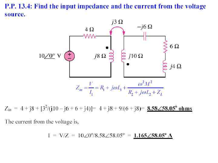
 Linear Transformers Zin R 1 and R 2 are winding resistances.
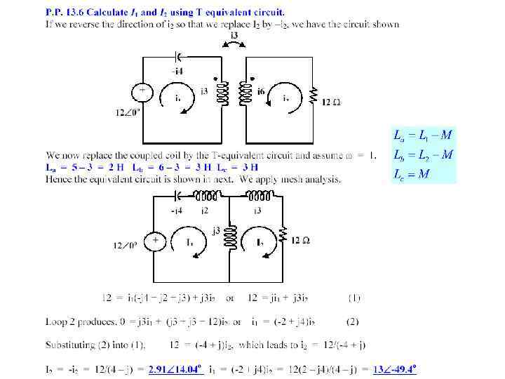
 Equivalent Circuit") T (or Y) Equivalent Circuit
T (or Y) Equivalent Circuit
 Equivalent Circuit") П (or ) Equivalent Circuit
П (or ) Equivalent Circuit
 EXAMPLE The parameters of a certain linear transformer are R 1 = 200 Ω, R 2 = 100 Ω, L 1 = 9 H, L 2 = 4 H, and k = 0. 5. The transformer couples an impedance consisting of an 800 Ω resistor in series with a 1 µF capacitor to a sinusoidal voltage source. The 300 V (rms) source has an internal impedance of 500 + j 100 Ω and a frequency of 400 rad/s. a) Construct a frequency-domain equivalent circuit of the system. b) Calculate the self-impedance of the primary circuit. c) Calculate the self-impedance of the secondary circuit. d) Calculate the impedance reflected into the primary winding. e) Calculate the scaling factor for the reflected impedance. f) Calculate the impedance seen looking into the primary terminals of the transformer. g) Calculate the rms value of the primary and secondary current. h) Calculate the rms value of the voltage at the terminals of the load and source. i) Calculate the average power delivered to the 800 Ω resistor. j) What percentage of the average power delivered to the transformer is delivered to the load?
 frequency-domain equivalent circuit of the system") S 0 LUTI 0 N a) frequency-domain equivalent circuit of the system
S 0 LUTI 0 N a) frequency-domain equivalent circuit of the system
. The self-impedance of the secondary circuit. d). The impedance reflected into the primary") c). The self-impedance of the secondary circuit. d). The impedance reflected into the primary winding. e). The scaling factor by which Z 22* is reflected is 8/9
c). The self-impedance of the secondary circuit. d). The impedance reflected into the primary winding. e). The scaling factor by which Z 22* is reflected is 8/9
. The impedance seen looking into the primary terminals of the transformer is the") f). The impedance seen looking into the primary terminals of the transformer is the impedance of primary winding plus the reflected impedance, thus g). Calculate I 1 and I 2
f). The impedance seen looking into the primary terminals of the transformer is the impedance of primary winding plus the reflected impedance, thus g). Calculate I 1 and I 2
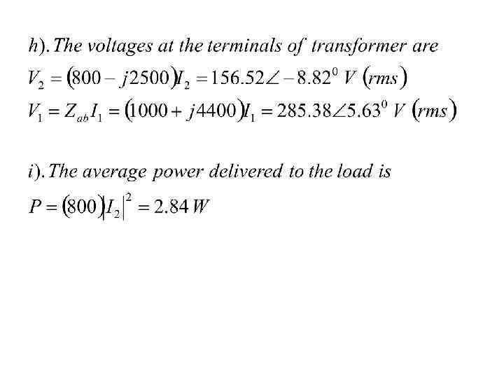
. The average power delivered to the transformer is Therefore") j). The average power delivered to the transformer is Therefore
j). The average power delivered to the transformer is Therefore
 1. Coils have very large reactance (L 1, L 2, M") Ideal Transformers (1/3) 1. Coils have very large reactance (L 1, L 2, M ~ ) 2. Coupling coefficient is equal to unity (k = 1) 3. Primary and secondary are lossless (series resistances R 1= R 2= 0)
Ideal Transformers (1/3) 1. Coils have very large reactance (L 1, L 2, M ~ ) 2. Coupling coefficient is equal to unity (k = 1) 3. Primary and secondary are lossless (series resistances R 1= R 2= 0)
") Ideal Transformers (2/3)
Ideal Transformers (2/3)
") Ideal Transformers (3/3)
Ideal Transformers (3/3)
 Types of Transformers • When n = 1, we generally call the transformer an isolation transformer. • If n > 1 , we have a step-up transformer (V 2 > V 1). • If n < 1 , we have a step-down transformer (V 2 < V 1).
 Impedance Transformation Zin
 How to make a transformer ideal? The linear transformer model Zin
 Impedance Matching Linear network
 Linear network 1 Linear network 2") Ideal Transformer Circuit (1/3) Linear network 1 Linear network 2
Ideal Transformer Circuit (1/3) Linear network 1 Linear network 2
 1") Ideal Transformer Circuit (2/3) 1
Ideal Transformer Circuit (2/3) 1
 c c") Ideal Transformer Circuit (3/3) c c
Ideal Transformer Circuit (3/3) c c
 Applications of Transformers • To step up or step down voltage and current (useful for power transmission and distribution) • To isolate one portion of a circuit from another • As an impedance matching device for maximum power transfer • Frequency-selective circuits
 Applications: Circuit Isolation When the relationship between the two networks is unknown, any improper direct connection may lead to circuit failure. This connection style can prevent circuit failure.
 Applications: DC Isolation Only ac signal can pass, dc signal is blocked.
 Applications: Load Matching
 Applications: Power Distribution