cafa6b45778d6a0466c1cddc2454fda6.ppt
- Количество слайдов: 49
 Lucent Technologies Wireless Networks Group 1999 Co-op Program PRESENTATION August 10, 1999
 Introduction Name School : Michael Phillip : The University of the West Indies (Trinidad and Tobago) Department : Customer Technical Support / Program Management (CTS/PM)
 Objectives 1. Cellular Systems Develop an understanding of a generic cellular system, and relate this to Lucent’s CDMA system - Autoplex 1000. 2. System Performance Research a cost effective direct data link between Lucent and BAM for the retrieval of CDMA service measurement data files, for performance analysis and report generation. 3. System Resources Model Develop a model that relates cellular traffic to system resources, for the analysis and specification of a CDMA hardware configuration, that will support the required traffic throughput.
 Benefits and Details The following sections attempt to address the following: • Give some of the benefits which may be derived by achieving the aforementioned objectives. • Give details on meeting the objectives, including areas in which improvements may be made.
 Objectives 1. Cellular Systems Develop an understanding of a generic cellular system, and relate this to Lucent’s CDMA system - Autoplex 1000. 2. System Performance Research a cost effective direct data link between Lucent and BAM for the retrieval of CDMA service measurement data files, for performance analysis and report generation. 3. System Resources Model Develop a model that relates cellular traffic to system resources, for the analysis and specification of a CDMA hardware configuration, that will support the required traffic throughput.
 1. Cellular Systems Description i To develop an understanding of the process involved, and the functional units that comprise a generic cellular system. • Relate this to Lucent’s CDMA cellular system – the Autoplex 1000 System.
 Cellular Systems Benefits • Provides the essential foundation and understanding, of the core product of the Network Wireless Systems group. • This then lends itself to better achievement of the said objectives.
 Cellular Systems Details This objective was achieved mainly through self-paced study, and lecture-based courses, which included: • CL 1000 A Autoplex System 1000 Overview. • LTW 300 L Principles of Digital Wireless Access Radio Communications. • LTW 100 L Introduction to Cellular and PCS Communications Systems and Technologies.
 Objectives 1. Cellular Systems Develop an understanding of a generic cellular system, and relate this to Lucent’s CDMA system - Autoplex 1000. 2. System Performance Research a cost effective direct data link between Lucent and BAM for the retrieval of CDMA service measurement data files, for performance analysis and report generation. 3. System Resources Model Develop a model that relates cellular traffic to system resources, for the analysis and specification of a CDMA hardware configuration, that will support the required traffic throughput.
 2 -1. System Performance – Data Collection Details • Investigation of existing data collection methods for the transfer of large data files such as Auto. PACE “. smd” files, ECP Service Measurements Data, and “. rop” files from customer sites to our in-house platforms. • Investigation of new possible methods and alternatives to existing data collection methods between customer sites and Lucent, Whippany. • Establish an internal contact to discuss the resources available for the “direct” collection of large volumes of data (10 – 100 Mb) files.
 Existing Data Collection Method This investigation lead to the FOA group, which in the past has collected data for Bell Atlantic Mobile, in regions which included: • North Jersey • Boston • Philadelphia
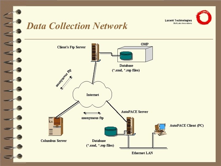
 The FOA Data-Collection System For any such system, there must be some medium for the data transmission, and an appropriate protocol must be used. In the FOA system, the following are utilized. • Transmission medium - Internet • Data transfer protocol - File transfer protocol
 System Implementation • It must be possible to perform a direct FTP from the client’s site, to Lucent’s Columbus server. • Software is loaded onto the client’s “machine”, which would automate the FTP procedures for transferring the relevant data files from their system (OMP) to the Columbus server, on a timely basis. • At Whippany, there is software loaded onto a machine which automates the retrieval of the data files from the Columbus server, and places it into the appropriate database for further processing.
 Benefits of the FOA System • Since the Internet is a shared resource and is readily available it represents the best compromise between cost and efficiency. • Furthermore, the international nature of the Internet would allow for rapid growth of the system, at minimal cost, especially in light of Lucent’s current expansion into international markets. • The ability to ready access the client’s system performance data, allows CTS personnel to respond quickly to system performance problems that they may have, and also, to be pro-active in following trends, and identifying potential problems that the client may experience.
 Security Concerns Security of data and system information may be of major concern to the client, and may be addressed as follows: • The Columbus server uses blind directories for its anonymous ftp, so in order to retrieve the files, one must know the exact directory, and names of the files. • The use of scripts to automate the data transfer means that no Lucent employee would need to physically enter the client’s system to retrieve data. • Third-party encryption software may be used to provide added security.
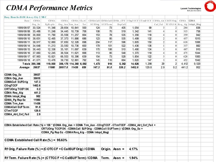
 2 -2. System Performance – Report Generation Details Work with FOA Engineering to establish a connection to the an Auto. PACE platform, for the following: • Generation of meaningful System Performance Reports that take a very general look at CDMA system health and CDMA system performance. • Creation of a report that utilizes Lucent Technologies’ recommended CDMA Performance Metrics for each Bell Atlantic Mobile Region.
 Implementation The list below gives the procedures for generating the appropriate reports. • Select the required database in the autopace. ini file. • Setup the a scenario, which includes the network elements of interest - ECP’s, Cells, etc. • Setup a report template which contains the performance metrics (counts) required. • Define the time period -Time, day, month, year. • Define the report type - Day vs. network element. • Setup the output processing - To printer or file, etc.
 Benefits • The ability to generate system performance data of the client’s system, allows CTS personnel to respond quickly to system problems, resulting in improved customer service. • Reports may be generated periodically, to observe trends which may indicate potential problems for the client’s system. This would allow CTS personnel to be pro-active in dealing with systems problems.
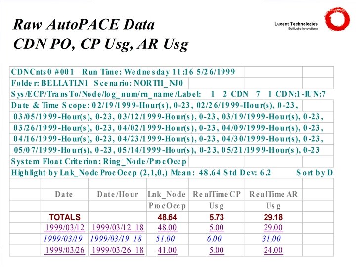
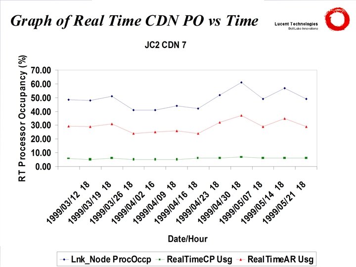
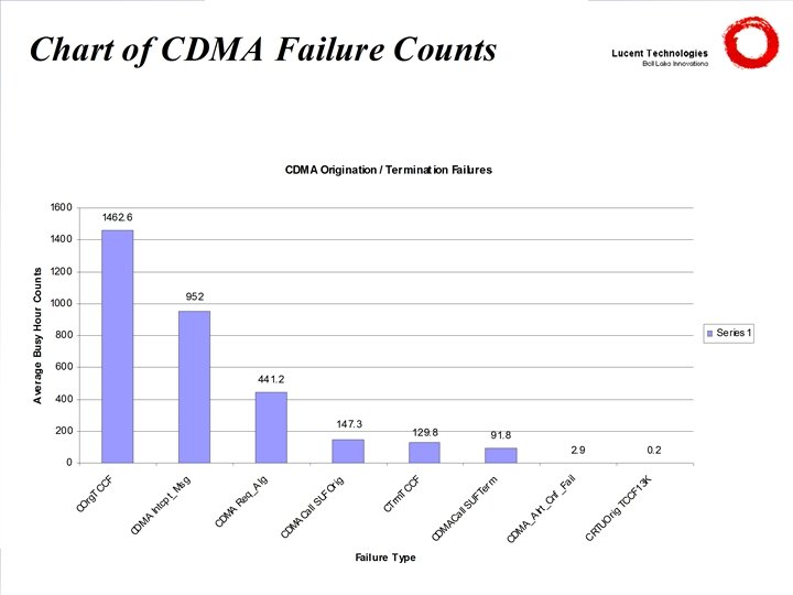
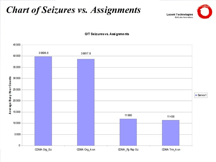
 Examples of Useful Reports CDN Processor Occupancy • CDN Real Time Processor Occupancy % (CDN_PO_%). • % of Real Time used by Call Processing (CPRTUsg). • % of Real Time used by Autonomous Reg. (ARRTUsg). Autonomous Registration Counts • Autonomous Registrations for Home subscribers. • Autonomous Registrations for Roamers. Assignment Counts • CDMA Originations Assigned. • CDMA Terminations Assigned. • AMPS Total Assigned (Orig + Term).
 Case Study • Customer had expectations that variations in CDN PO should have been driven by Call Processing, but their observations did not support this. • Reports generated by Auto. PACE were used in the subsequent investigation and showed that Autonomous Registration was the pre-dominant contributor to the CDN PO variations. • This information was then used in educating the client, and has since been applied in some situations. • The data was also used in an Internal Study on Access Failures for CDMA systems.
 Objectives 1. Cellular Systems Develop an understanding of a generic cellular system, and relate this to Lucent’s CDMA system - Autoplex 1000. 2. System Performance Research a cost effective direct data link between Lucent and BAM for the retrieval of CDMA service measurement data files, for performance analysis and report generation. 3. System Resources Model Develop a model that relates cellular traffic to system resources, for the analysis and specification of a CDMA hardware configuration, that will support the required traffic throughput.
 3. CDMA System Resources Model Description Development of a Model that would be used to analyze and specify the CDMA hardware configurations that support the traffic (data packets) throughput between the cell site and switch components, in terms of the following: • Identification of the most constraining resource or component of the system. • Calculation of the maximum load based on given resources. • Determination of resources required for a pre-determined load.
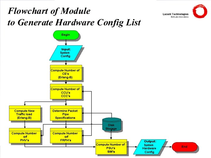
 CDMA System Hardware Model Key: CE CCC CCU DFI DLTU FRPH PHA PHV PSU SM TSI Channel Element CDMA Cluster Ctrl CDMA Channel Unit Digital Facilities Interface Digital Line Trunk Unit Frame Relay Protocol Hnd for ATM Protocol Hnd for Voice Packet Switching Unit Switching Module Time Slot Interchanger PSTN Public Switched Telephone Network
 Model Design The model consists of the following: • The cell hardware component necessary for call processing in a Series II cell-site. • The packet pipe specifications, which are chosen to adequately handle the traffic between cell and switch. • The switch hardware components, of a 5 ESS switch, which are required to support only a single cell-site.
 Model Used In Analysis
 -") Cell Components The cell components considered in the model are: • Channel Elements(CE) - this handles an individual call. • CDMA Channel Unit(CCU) - this contains groups of channel elements. • CDMA Cluster Controller(CCC) - this unit controls cluster of CCU’s and provides the interface to the TDM bus.
Cell Components The cell components considered in the model are: • Channel Elements(CE) - this handles an individual call. • CDMA Channel Unit(CCU) - this contains groups of channel elements. • CDMA Cluster Controller(CCC) - this unit controls cluster of CCU’s and provides the interface to the TDM bus.
 Packet Pipe Components The packet pipe essentially consists of groups of contiguous channels within a T 1/E 1 line, and specifications which comprise: • DS 0 Rate - the data transfer rate of an individual channel (eg. 64 kbps, 56 kbps). • Vocoder Rate - the digitized speech rate handled by the speech coder (eg. 8 kbps, 13 kbps). • Packet Pipe Size - the number of contiguous DS 0 channels used, within a T 1/E 1 line.
 Switch Components The switch components considered are: • Protocol Handler - this handles speech encoding/decoding for voice (PHV) and the selection of speech frames. • Frame Relay - this terminates the packet pipe from the Protocol Handler cell onto the packet bus of the switch. (FRPH) • Packet Switching - this contains the bus which performs the Unit(PSU) the packet switching function in the switch • Switching Module(SM) - this contains the SM processors and the switching related modules of the switch.
 Assumptions • Traffic load to the cell follows an Erlang B Model, which means that call may originate from an infinite number of source, and blocked calls are cleared from the system. • The error incurred by not including channel element pooling in the analysis, may be considered to be small for the range of traffic loads in question. • The offered load to the cell is uniformly distributed among sectors. • The air-interface limit, on a per sector/carrier level may not be exceeded (constraint).
 Implementation The Model was implemented in the form of a computer application, as this would allow a fairly high degree of automation. • Borland C++ Builder 4. 0 was used, as it provides both the power of C++, as found in Visual C++, but with the ease of GUI building as found in Visual Basic, all in one package. • Furthermore, as a result of past experience in C programming, there would be a shorter learning curve. • A highly modular approach to algorithm design was adopted, to both reduce complexity, and to facilitate improvements on individual modules, without significantly affecting the rest of the application.
 Future Improvements • Addition of a graphical user interface, preferably keeping platform independence in mind. • Modification of the Erlang B routines, to take channel element pooling and unbalanced loading of sectors into account. • Support for Packet Pipe-16 and other enhancements. • Support for modeling a system of one switch and multiple cell sites. • Placement of a cost factor onto system components, so that cost effectiveness may be taken into account in the analysis.
 Benefits • Provides some measure of forecasting, in determining when the client should reach capacity, given an estimate of the rate of growth of traffic to the cell. • Provides a means of running “what-if” scenarios, from the point of view of quantities of specific system components, in determining the most cost effective path towards capacity growth. • Increases the productivity of the user, by eliminating the need to perform manual calculations a table look-ups, and in addition, reducing human error.
 Case Study Consider a system with the following specifications: Offered load Probability of blocking Number of sectors Users in Soft Hand-off : 39. 3 Erlangs : 2% : 35% Packet pipe DS 0 rate CE vocoder rate : 56 kbps : 13 kbps Type of PHV : PHV 3
 Calculations Using the Erlang-B tables • Number of CE’s = 49 Including Soft H/O users, • Number of Traffic CE’s = 49 x 1. 35 = 66. 15 67 Require 1 CE - Paging Ch, 1 CE - Pilot/Sync/Access per sector • Number of Overhead CE’s = 3 x (1 + 1) = 6 Total no of CE’s is the sum of Traffic CE’s and Overhead CE’s • Number of CE’s = 67 + 6 = 73
 Calculations One ECU contains 10 CE’s • Number of ECU’s = 73/10 = 7. 3 8 Total available CE’s • Number of Traffic CE’s = (8 x 10) - 6 = 74 Total traffic now supported is 62. 9 Erlangs (from Tables) Offered load per sector = 62. 9/3 = 20. 967 Erlangs • Number of carriers required = 3 (20. 967/3 < 7. 4) From Packet Pipe table, each 8 DS 0 PP (at 56 kbps) can support 19, 13 kbps CE’s • Number of PP’s = 74/19 = 3. 89 4 (8 DS 0 in width)
") Calculations Each T 1 line supports 24 DS 0’s (PP’s cannot span T 1’s) • Number of T 1 lines = (4 x 8)/24 = 1. 333 2 Each Packet Pipe must terminate at a CCC • Number of CCC’s = 4 From tables, 74 CE’s support an offered load of 62. 9 Erlangs For no blocking, and operation at 90% efficiency, • Total number of vocoders = 63/0. 90 = 70 Each PHV 3 contains 16 vocoders • Number of PHV 3’s = 70/16 = 4. 375 5
Calculations Each T 1 line supports 24 DS 0’s (PP’s cannot span T 1’s) • Number of T 1 lines = (4 x 8)/24 = 1. 333 2 Each Packet Pipe must terminate at a CCC • Number of CCC’s = 4 From tables, 74 CE’s support an offered load of 62. 9 Erlangs For no blocking, and operation at 90% efficiency, • Total number of vocoders = 63/0. 90 = 70 Each PHV 3 contains 16 vocoders • Number of PHV 3’s = 70/16 = 4. 375 5
 Calculations PP’s terminate at an FRPH, which is limited to 32 time slots (1 DS 0 per slot) and can support upto 64 vocoders. 4, 8 DS 0 PP’s require 32 slots, and supports 76 CE’s (4 x 19) • Number of FRPH’s = 2 • (3, 8 DS 0 + 1, 8 DS 0)
 Summary • Number of Carriers : 3 • • : 74 : 6 : 8 : 4 Number of Traffic CE’s Number of Overhead CE’s Number of ECU’s Number of CCC’s • 4 Packet Pipes of size 8 DS 0’s • Number of T 1’s : 2 • Number of PHV 3’s • Number of FRPH’s : 5 : 2
 Acquired Skills/Knowledge • An understanding of the fundamental theory behind the IS-95 Standard. • An understanding of the processes involved in the operations of a CDMA cellular system. • An appreciation for performance metrics used in monitoring the health of a CDMA cellular system. • Experience in Object-Oriented Programming (C++). • A broader understanding of communications technology.
 Courses Completed • CL 1000 A - Autoplex System 1000 Overview • LTT 600 W - Basic Traffic Theory and Trunk Engineering • LTW 300 L - Principle of Digital Wireless Access Radio Communications • LTW 100 L - An Introduction to Cellular and Personal Communications Systems and Technologies • LTW 362 L - Introduction to CDMA Technology and the IS-95 Standard • LTW 364 L - Introduction to Product Architecture, Operations and System Engineering for IS-95 • LTP 400 L - Digital Signal Processing in Wireless Communication Systems • LCL 200 H - Object-Oriented Programming in C++
 References • Auto. PACE Perofrmance Analysis User’s Guide - Lucent, 401 -660 -126 • AUTOPLEX Cellular Telecommunications System 1000 CDMA RF Engineering Guidelines - Lucent, 401 -614 -012 • Basic Traffic Analysis - Roberta Martine • Borland C++ Builder Programming Explorer - J. Mischel and J. Duntemann • CDMAOne for RF Engineers, part 2 - Tanveer ul Haq • Introduction to the Auto. PACE System (CL 1517) - Lucent • System Capacity and Engineering Student Guide (CL 1001 PC) - Lucent • The C++ Programming Language, 3 rd Ed. - Bjarne Stroustrup