

L10 Traversing.pptx
- Количество слайдов: 31
 Lecture 10
 TRAVERSING Definition: • A traverse is a series of consecutive lines whose lengths and directions have been measured. Why do we use traverses? • The purpose of establishing a traverse is to extend the horizontal control. These surveys usually begin with one given vertical and two horizontal controls. Although you may need more depending on the size of the project.
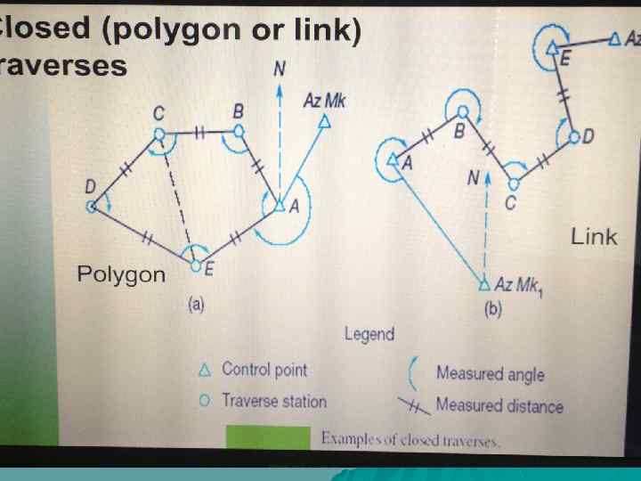
 Closed and Open Traversing What is a closed traverses ? Closed Traverse: • A closed traverse is one that starts and ends at known points and directions, whether the shape is closed or not. • A closed traverse can be a polygon (closed shape) or link ( closed geometrically but open shape)
 Open Traverses • Open traversing starts with a known predetermined point already determined with respect to a horizontal datum, and end at an unknown horizontal position further down the line. Thus open traverses end without closing the loop and are geometrically and mathematically open. • Open traverses are typically used for plotting a strip of land which will be used to plan a route in road construction
 Open Traverses are not used in engineering control applications, why? • The problem: there is no way to check the for the errors; you will have to accept whatever coordinates computed.
 Open Traverse Example
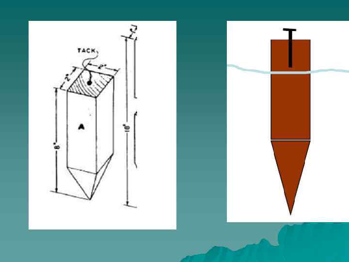
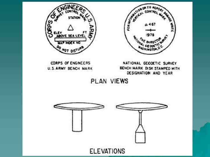
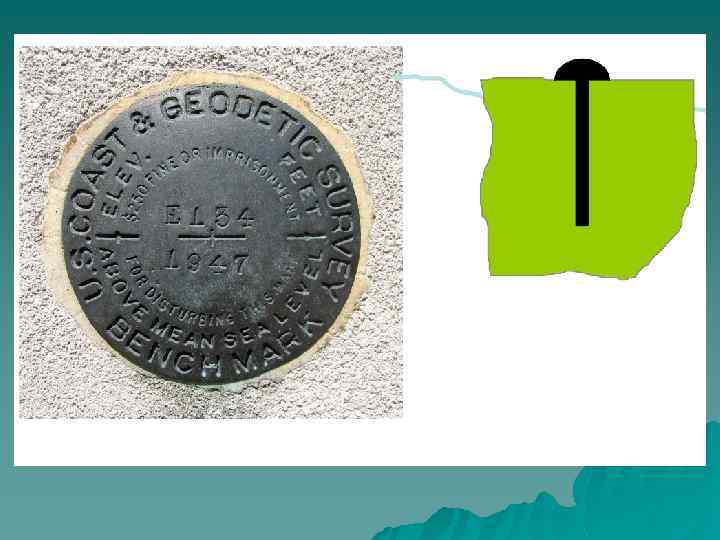
 Traversing Stations and pins • Traversing stations are chosen in safe and easy to access locations (reconnaissance) • Lines should be as long as possible to reduce errors. • Bench marks are used to help establish the traverse.
 Traversing by Interior Angles • All internal angles and all horizontal distances are measured. • Each angle is measured in direct and reverse mode • A line of known direction (Azimuth) should either be given or assumed.
 Questions u What is a line with known direction? u If the line of known direction is not a member of the traverse, the angle to a traverse member should be measured. Why?
 ANGULAR MISCLOSURE u
 Step 1: Check Allowable Angle Misclosure u
 Angle misclosure A B D C
 Example u
 u. If angles are accepted, correct by dividing the error equally among the angles
180 degrees!") Step 2: Balance interior angles Sum of the interior angles must equal (n-2)180 degrees!
Step 2: Balance interior angles Sum of the interior angles must equal (n-2)180 degrees!
 Step 3: Computation of Preliminary Azimuths or Bearings
 Step 3: Computation of Preliminary Azimuths or Bearings
") Step 4: Compute Departures and Latitudes X 0 Departure Y = L sin (bearing) Latitude X = L cos (bearing) Y
Step 4: Compute Departures and Latitudes X 0 Departure Y = L sin (bearing) Latitude X = L cos (bearing) Y
 Departures and Latitudes u Y = L sin u X = L cos
 u
u
 Step 5: Compute Linear Misclosure Because of errors in the measured angles and distances there will be a linear misclosure of the traverse. Another way of illustrating this is that once you go around the traverse from point A back to point A’ you will notice that the summation of the departures and latitudes do not equal to zero. Hence a linear misclosure is introduced.
 Compute Linear Misclosure u
 Step 6: Compute Relative Precision
 Step 7: Adjust Departures and Latitudes
 Step 8: Compute Rectangular Coordinates XB = XA + YB = YA +
 References http: //www. engr. mun. ca/~sitotaw/Site/Fall 2007_files/TP_Manual_Close. Travers. ENGI 3703. pdf http: //engineeringtraining. tpub. com/14069 /css/14069_463. htm http: //www. firefightermath. org/index. php? option=com_content&view=article&id=58& Itemid=72 http: //www. globalsecurity. org/military/libra ry/policy/army/fm/3 -34 -331/ch 6. htm http: //classof 1. com/homework_answers/civ il_engineering/traverse_surveying/ www. globalsecurity. org http: //www. floridageomatics. com/publicati ons/gfl/chapter-three. htm http: //www. oc. nps. edu/oc 2902 w/geodesy/ geolay/gfl 84 b_a. htm