
Lecture № 1. 5. Location information in a


- Размер: 932 Кб
- Количество слайдов: 31
Описание презентации Lecture № 1. 5. Location information in a по слайдам
Lecture № 1. 5. Location information in a memory, addressing methods. The main function of any processor for the sake of which it also is created — this performance of commands. The system of the commands which are carried out by the processor, represents something similar to the table of the validity of logic elements or the table of operating modes of more difficult logic chips. That is it defines logic of operation of the processor and its reaction to these or those combinations of external events. Writing of programs for microprocessor system — the major and often the most labor-consuming development stage of such system. And for creation of effective programs it is necessary to have at least the most general idea of system of commands of the used processor. The most compact and fast programs and subprograms are created in the Assembler language which
use without knowledge of system of commands is absolutely impossible, after all the Assembler language represents symbolical record of digital codes of computer language, codes of commands of the processor. Certainly, for development of the software there are every possible software. To use them it is usually possible and without knowledge of system of commands of the processor. More often programming languages of high level, such as Pascal and SI are applied. However the knowledge of system of commands and the Assembler language allows to increase several times efficiency of some most important parts of the software of any micropro-cessor system — from the microcontroller to the personal computer. For this reason in this chapter we will consider the main types of commands which are available for the majority of processors, and features of their application. Each command, chosen (read) of memory the processor, defines algorithm of behavior of the processor on the next some steps. The code of command speaks about what operation should be executed to the processor and with what operands (that is codes of data) where to take initial information for command execution
and where to place result (if it is necessary). The code of command can borrow from one to several bytes, and the processor learns about that, how many command byte he should read, from the first byte read by it or a word. In the processor the code of command is deciphered and will be transformed to a set of the micro operations which are carried out by separate knots of the processor. But to the developer of microprocessor systems this knowledge isn’t too important, to it the result of performance of this or that command is important only. • 2. 3. 1. Addressing of operands The most part of commands of the processor works with codes of data (operands). One commands demand entrance operands (one or two), others give out target operands (one operand is more often). Entrance operands are called still as operands sources, and days off are called as operands receivers. All these codes of operands (entrance and target) should settle down somewhere. They can be in internal registers of the processor (the most convenient and fast option). They can settle down in system memory (the most widespread option). At last, they can be in input-output devices (the most exceptional case).
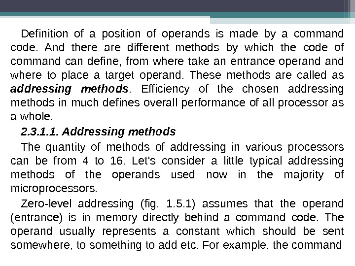
Definition of a position of operands is made by a command code. And there are different methods by which the code of command can define, from where take an entrance operand where to place a target operand. These methods are called as addressing methods. Efficiency of the chosen addressing methods in much defines overall performance of all processor as a whole. 2. 3. 1. 1. Addressing methods The quantity of methods of addressing in various processors can be from 4 to 16. Let’s consider a little typical addressing methods of the operands used now in the majority of microprocessors. Zero-level addressing (fig. 1. 5. 1) assumes that the operand (entrance) is in memory directly behind a command code. The operand usually represents a constant which should be sent somewhere, to something to add etc. For example, the command
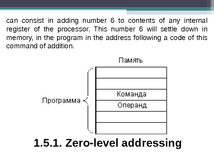
can consist in adding number 6 to contents of any internal register of the processor. This number 6 will settle down in memory, in the program in the address following a code of this command of addition. 1. 5. 1. Zero-level addressing
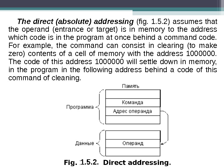
The direct (absolute) addressing (fig. 1. 5. 2) assumes that the operand (entrance or target) is in memory to the address which code is in the program at once behind a command code. For example, the command can consist in clearing (to make zero) contents of a cell of memory with the address 1000000. The code of this address 1000000 will settle down in memory, in the program in the following address behind a code of this command of cleaning. 1. 5. 2.
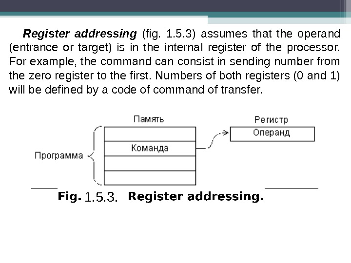
Register addressing (fig. 1. 5. 3) assumes that the operand (entrance or target) is in the internal register of the processor. For example, the command can consist in sending number from the zero register to the first. Numbers of both registers (0 and 1) will be defined by a code of command of transfer. 1. 5. 3.
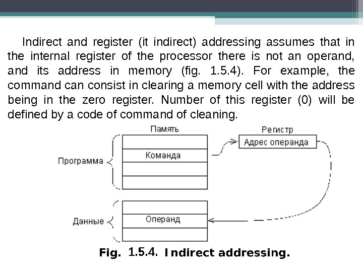
Indirect and register (it indirect) addressing assumes that in the internal register of the processor there is not an operand, and its address in memory (fig. 1. 5. 4). For example, the command can consist in clearing a memory cell with the address being in the zero register. Number of this register (0) will be defined by a code of command of cleaning. 1. 5. 4.
Less often two more methods of addressing meet. Autoincremental addressing is very close to indirect addressing, but differs from it that after command execution contents of the used register increase by unit or on two. This method of addressing is very convenient, for example, at serial processing of codes from a data file being in memory. After processing of any code the address in the register will already indicate the following code from the massif. When using indirect addressing in this case it should to increase contents of this register separate command. Autodecremental addressing works probably on autoincremental, but only contents of the chosen register decrease by unit or on two before command execution. This addressing is also convenient when processing data files. Sharing of autoincremental and autodecremental addressings allows to organize memory of push-down type.
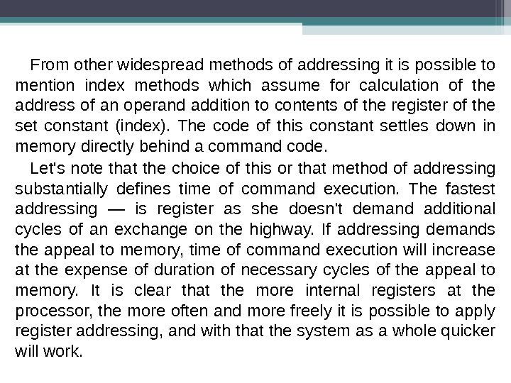
From other widespread methods of addressing it is possible to mention index methods which assume for calculation of the address of an operand addition to contents of the register of the set constant (index). The code of this constant settles down in memory directly behind a command code. Let’s note that the choice of this or that method of addressing substantially defines time of command execution. The fastest addressing — is register as she doesn’t demand additional cycles of an exchange on the highway. If addressing demands the appeal to memory, time of command execution will increase at the expense of duration of necessary cycles of the appeal to memory. It is clear that the more internal registers at the processor, the more often and more freely it is possible to apply register addressing, and with that the system as a whole quicker will work.
• 2. 3. 1. 2. Memory segmentation Speaking about addressing, it is impossible to bypass a question of the memory segmentation applied in some processors, for example in IBM PC compatible processors of personal computers. In the Intel 8086 processor segmentation of memory is organized as follows. All memory of system is represented not in the form of continuous space, and in the form of several pieces — given size segments (on 64 Kb) which situation in space of memory can be changed a program way. For storage of codes of addresses of memory separate registers, and pairs of registers are used not: • the segment register defines the address of the beginning of a segment (that is the provision of a segment in memory); • the index register (the shift register) defines the provision of the working address in a segment.
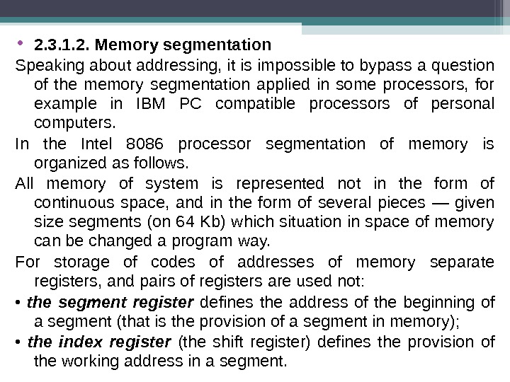
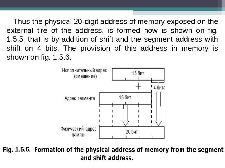
Thus the physical 20 -digit address of memory exposed on the external tire of the address, is formed how is shown on fig. 1. 5. 5, that is by addition of shift and the segment address with shift on 4 bits. The provision of this address in memory is shown on fig. 1. 5. 6. 1. 5. 5.
1. 5. 6.
The segment can begin only on 16 -byte limit of memory (as the address of the beginning of a segment, in fact, has four younger zero categories, apparently from fig. 1. 5. 5), that is from the address, multiple 16. These admissible borders of segments are called as limits of paragraphs. Let’s note that segmentation introduction, first of all, is connected with that internal registers of the processor 16 -digit, and the physical address of memory 20 -digit (the 16 -digit address allows to use memory only in 64 Kb that is obviously not enough). In the MC 68000 processor which has appeared at the same time of Motorola firm internal registers 32 -bit therefore there problems of segmentation of memory don’t arise. More difficult methods of segmentation of memory are applied also. For example, in the Intel 80286 processor in the so-called protected mode the address of memory is calculated according to fig. 1. 5. 7.
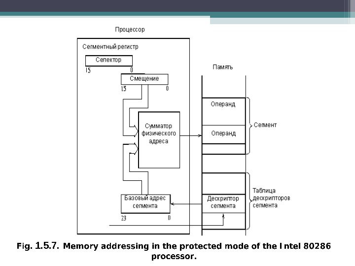
1. 5. 7.
The base (initial) address of segments, and the codes of selectors defining addresses in memory on which descriptors (that is descriptors) segments are stored in this case is stored in the segment register not. The memory area with descriptors is called as the table of descriptors. Each descriptor of a segment contains the base address of a segment, the size of a segment (from 1 to 64 Kb) and its attributes. The base address of a segment has word length of 24 bits that provides addressing of 16 Mb of physical memory. Thus, on the adder calculating the physical address of memory, contents of the segment register, as in the previous case, and the base address of a segment from the table of descriptors move not. Even more difficult method of addressing of memory with segmentation is used in the Intel 80386 processor and in later models of processors of Intel firm. This method is illustrated fig. 1. 5. 8.
1. 5. 8.
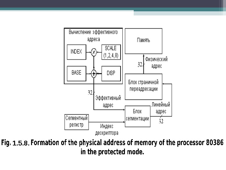
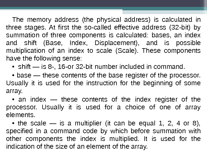
The memory address (the physical address) is calculated in three stages. At first the so-called effective address (32 -bit) by summation of three components is calculated: bases, an index and shift (Base, Index, Displacement), and is possible multiplication of an index to scale (Scale). These components have the following sense: • shift — is 8 -, 16 -or 32 -bit number included in command. • base — these contents of the base register of the processor. Usually it is used for the instruction for the beginning of some array. • an index — these contents of the index register of the processor. Usually it is used for a choice of one of array elements. • the scale — is a multiplier (it can be equal 1, 2, 4 or 8), specified in a command code by which before summation with other components the index is multiplied. It is used for the indication of the size of an element of the array.
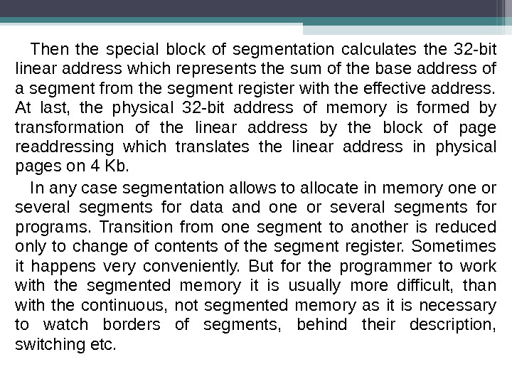
Then the special block of segmentation calculates the 32 -bit linear address which represents the sum of the base address of a segment from the segment register with the effective address. At last, the physical 32 -bit address of memory is formed by transformation of the linear address by the block of page readdressing which translates the linear address in physical pages on 4 Kb. In any case segmentation allows to allocate in memory one or several segments for data and one or several segments for programs. Transition from one segment to another is reduced only to change of contents of the segment register. Sometimes it happens very conveniently. But for the programmer to work with the segmented memory it is usually more difficult, than with the continuous, not segmented memory as it is necessary to watch borders of segments, behind their description, switching etc.
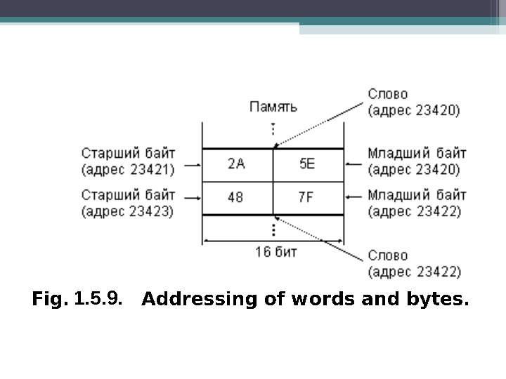
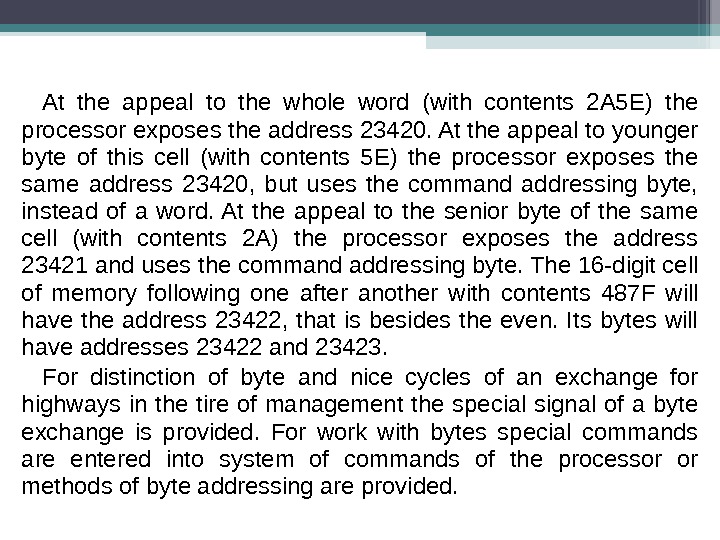
• 2. 3. 1. 3. Addressing of bytes and words Many processors having word length 16 or 32, are capable to address not only the whole word in memory (16 -digit or 32 -bit), but also separate bytes. In each word the address is thus allocated for each byte. So, in case of 16 -digit processors all words in memory (16 -digit) have even addresses. And the bytes entering into these words, can have both even addresses, and odd. For example, let the 16 -digit cell of memory has the address 23420, and the code 2 А 5 Е is stored in it (fig. 1. 5. 9).
1. 5. 9.
At the appeal to the whole word (with contents 2 А 5 Е) the processor exposes the address 23420. At the appeal to younger byte of this cell (with contents 5 Е) the processor exposes the same address 23420, but uses the command addressing byte, instead of a word. At the appeal to the senior byte of the same cell (with contents 2 А) the processor exposes the address 23421 and uses the command addressing byte. The 16 -digit cell of memory following one after another with contents 487 F will have the address 23422, that is besides the even. Its bytes will have addresses 23422 and 23423. For distinction of byte and nice cycles of an exchange for highways in the tire of management the special signal of a byte exchange is provided. For work with bytes special commands are entered into system of commands of the processor or methods of byte addressing are provided.
• 2. 3. 2. Processor registers As it was already mentioned, internal registers of the processor represent scratch-pad memory of the small size which is intended for temporary storage of office information or data. The number of registers in different processors can be from 6 — 8 to several tens. Registers can be universal and specialized. Specialized registers which are present at the majority of processors — it is the register — the counter of commands, the register of a condition (PSW), the register of the index of a stack. Other registers of the processor can be both universal, and specialized. For example, in the 16 -digit T-11 processor of DEC firm there were 8 registers of general purpose (RON) and one register of a condition. All registers had on 16 categories. From registers of general purpose one was taken away under the counter of commands, another — under the stack index. All other registers of general purpose are completely interchangeable, that is have universal appointment, can store both data, and addresses (indexes), indexes etc. The most admissible memory size for this processor made 64 Kb (the memory address 16 -digit).
In the 16 -digit MC 68000 processor of Motorola firm there were 19 registers: 16 -digit register of a condition, 32 -bit register of the counter of commands, 9 registers of the address (32 -bit) and 8 registers of data (32 -bit). Two registers of the address are taken away under stack indexes. The most admissible volume of addressed memory — 16 Mb (the external tire of the address 24 -digit). All 8 registers of data are interchangeable. 7 registers of the address – too are interchangeable. In the 16 -digit Intel 8086 processor which base in the line of the processors used in personal computers, became realized essentially other approach. Each register of this processor has the special appointment, and replace each other registers can only partially or can’t in general. Let’s stop on features of this processor in more detail. The processor 8086 has 14 registers word length on 16 bits. From them four registers (AX, BX, CX, DX) — is registers of data, each of which besides storage of operands and results of operations has also the specific appointment:
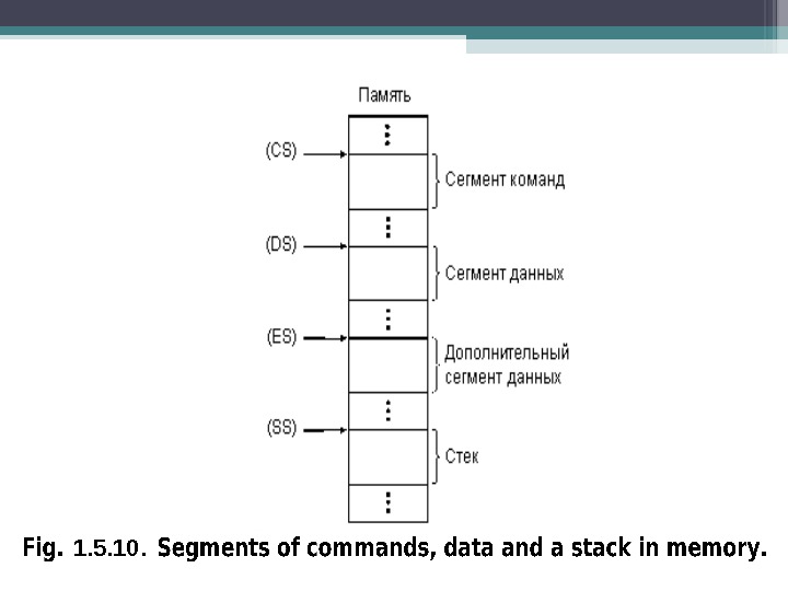
• the register AX — multiplication, division, an exchange with input-output devices (input and output command); • the register BX — the base register in address calculations; • the register CX — the counter of cycles; • the register DX — definition of the address of input-output. For registers of data there is a possibility of separate use of both bytes (for example, for the register AX they have AL designations the-junior byte and AH — the senior byte). The following four internal registers of the processor — it is segment registers, each of which defines the provision of one of working segments (fig. 1. 5. 10): • the register CS (Code Segment) corresponds to a segment of the commands executed at present; • the register DS (Data Segment) corresponds to a segment of data with which the processor works; • the register ES (Extra Segment) corresponds to an additional segment of data; • the register SS (Stack Segment) corresponds to a stack segment.
1. 5. 10.
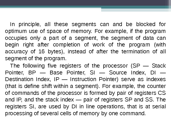
In principle, all these segments can and be blocked for optimum use of space of memory. For example, if the program occupies only a part of a segment, the segment of data can begin right after completion of work of the program (with accuracy of 16 bytes), instead of after the termination of all segment of the program. The following five registers of the processor (SP — Stack Pointer, BP — Base Pointer, SI — Source Index, DI — Destination Index, IP — Instruction Pointer) serve as indexes (that is define shift within a segment). For example, the counter of commands of the processor is formed by pair of registers CS and IP, and the stack index — pair of registers SP and SS. The registers SI, are used by DI in line operations, that is at serial processing of several cells of memory by one command.
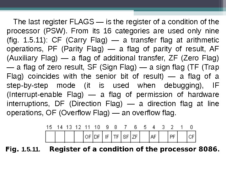
The last register FLAGS — is the register of a condition of the processor (PSW). From its 16 categories are used only nine (fig. 1. 5. 11): CF (Carry Flag) — a transfer flag at arithmetic operations, PF (Parity Flag) — a flag of parity of result, AF (Auxiliary Flag) — a flag of additional transfer, ZF (Zero Flag) — a flag of zero result, SF (Sign Flag) — a sign flag (TF (Trap Flag) coincides with the senior bit of result) — a flag of a step-by-step mode (it is used when debugging), IF (Interrupt-enable Flag) — a flag of permission of hardware interruptions, DF (Direction Flag) — a direction flag at line operations, OF (Overflow Flag) — an overflow flag. 1. 5. 11.
Bits of the register of a condition are established or cleared depending on result of execution of the previous command used by some commands of the processor. Bits of the register of a condition can be established and be cleared also by special commands of the processor (about system of commands of the processor it will be told in the following section). In many processors the special register called by the accumulator (that is with the store) is allocated. Thus, as a rule, only this register accumulator can participate in all operations, only through it interaction with input-output devices can be made. Sometimes in it the result of any executed command (in this case speak even about «storage» architecture of the processor) is located. For example, in the processor 8086 AH it is possible to consider the register of data as a peculiar
accumulator as he surely participates in multiplication and division commands, and also only through it it is possible to send data to the device of input-output and from the input-output device. Allocation of the special register accumulator simplifies structure of the processor and accelerates transfers of codes in the processor, but in certain cases slows down system work as a whole as all flow of information should pass through one register accumulator. In a case when some registers of the processor are completely interchangeable, such problems don’t arise.